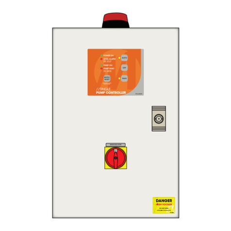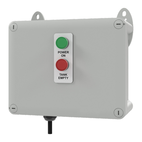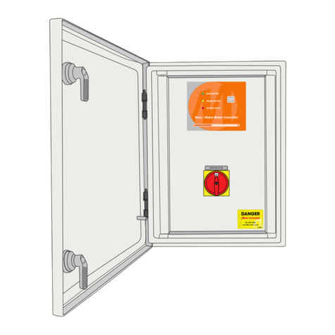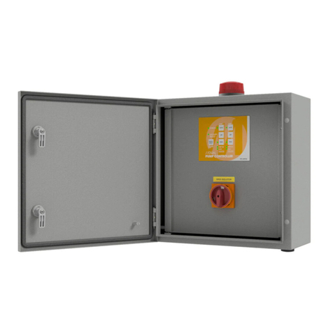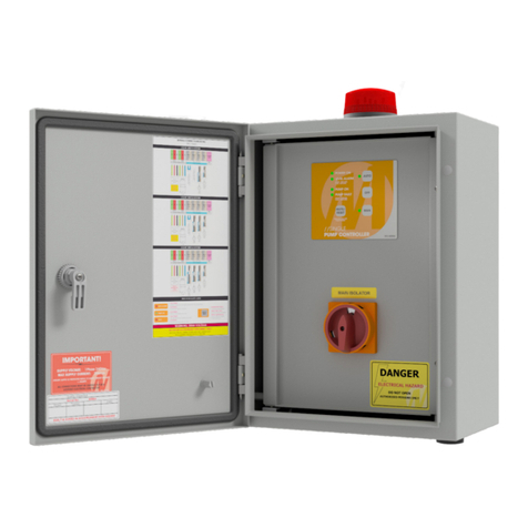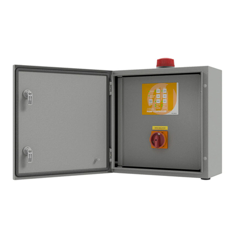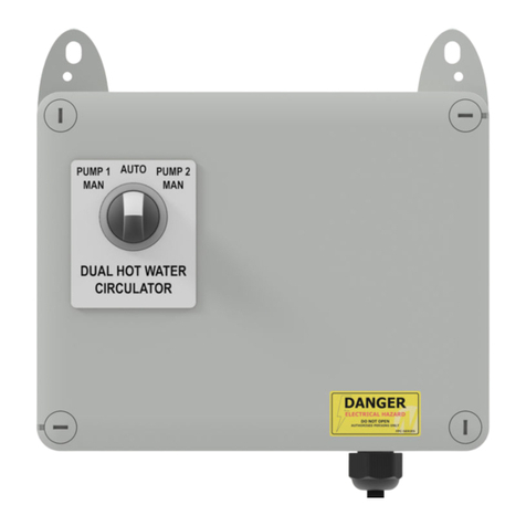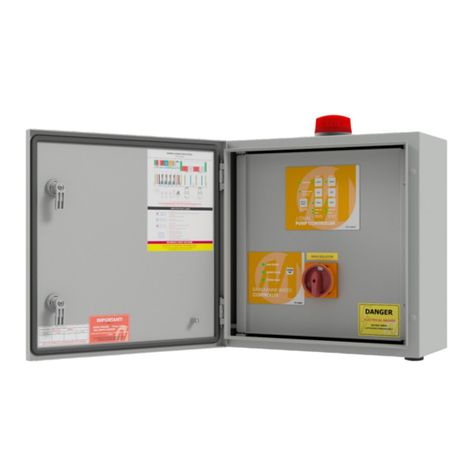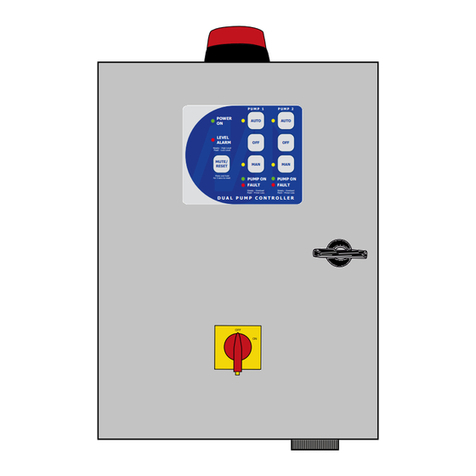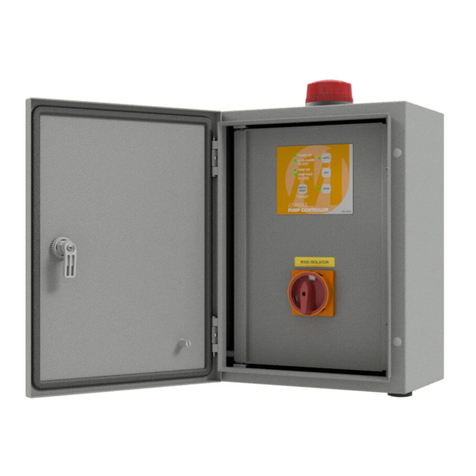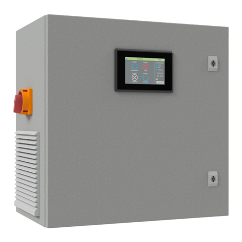
SUPPLY VOLTAGE: 240VAC
OPERATING VOLTAGES: 15VDC
5VDC
PUMP OUTPUT
- 240VAC, 8A MAX
- Active switched (neutral is always connected)
SOLENOID VALVE OUTPUT
- 15VDC, changing polarity output
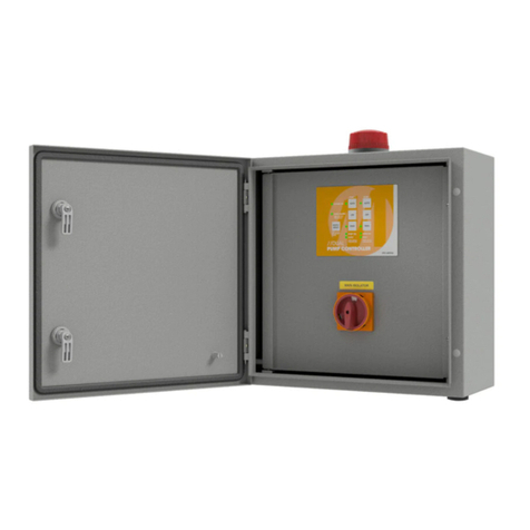
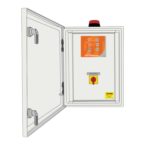
INDICATORS / TEST BUTTON
- Keypad membrane label
o Mains water LED (Red)
o Tank water LED (Green)
o Clicker Dome Test Button
FLOAT SWITCH INPUT
- Theoatswitchinputisa15V,10mAsignal.
PRESSURE SWITCH INPUT
- The pressure switch input is a 15V, 10mA signal
- If the system is running on tank water and the
Pressure Switch input is closed then the pump output
willbeswitchedoff.Thepumpoutputwillbeswitched
backonwhenthePressureSwitchinputopens.
OPERATIONAL OVERVIEW continued
OPERATION: PUMP / SOLENOID VALVE CONTROL
- When the Float input is closed the power to the pump
will be switched on and the solenoid valve will be
closed.Thesystemisnowrunningontankwaterand
theTankWaterLEDwilllight.
- When the Float input is open the power to the pump
willbeswitchedoffandthevalvewillbeopened.The
system is now running on mains water and the Mains
WaterLEDwilllight.
OPERATION: SOLENOID SWITCHING
- The solenoid valve will be given two pulses each time
itswitches.Thiswillensurethatithasoperated
correctly.
OPERATION: TEST BUTTON
- When the test button is held in for approx 2s, the
solenoid valve will temporarily change state and after
approx2swillrevertbacktoitsoriginalstate.Ifthe
pump is on at the time the test button is pressed it will
beswitchedoffwhenchangingstate.
OPERATION: POWER FAILURE
- In the event of power failure the solenoid valve will
open.
INSTALLATION GUIDE
WARNING: Allelectricalconnectionsmustbecarriedoutbyasuitablyqualiedandregisteredelectrician.
CONTROLLER MOUNTING:
1 Enclosure must be mounted in a vertical position,
xedtoeitherawallorframe,ensuringcable
entry points are located on the under side of the
enclosure and that all penetrations made, are
weather proof, and do not compromise the IP
ratingoftheenclosure.
FLOAT SWITCH SETUP:
1 Drilla16mmholeinroofoftank.InstallCable
Gland with dome nut on the outside of the tank
andsecurelocknutontheinsideofthetank.
2 Feed Float Switch cable through the gland
from the inside of the tank until in the correct
position.
3 Allow ball of Float Switch to hang +/- 100mm
aboveoutletofthetank.Tightendomenuton
CableGlandtosecurecable.
4 Connect Float Switch to corresponding connectors
on the PCB (see Figure 1).
VALVE SETUP:
1 Valve must be installed in accordance with appropriate
PlumbingIndustryCodeofPractice.Ensuredirectionof
ow‘’isnoted.
2 Ensuremanualoverrideleverissetto‘closed’position.
Flow control adjustment (on top of Valve) should be set
fullyopen(anti-clockwise).
3 Connect Valve to corresponding connectors on the PCB
(see Figure 1).
4 Should the Valve be ‘Closed’ when in fact it should be
‘Open’,reversewiresonPCBconnection(Polarity).
PUMP CONNECTION:
1 Connect Pump/Pressure Controller to appropriate
‘Pump’ terminals on PCB (8amp Max) (see Figure 1).
POWER SUPPLY CONNECTION:
1 Connect Power Supply (from ‘RCD’ Protected circuit)
to appropriate ‘Supply’ terminals on PCB (see Figure 1).
ThefollowingisanoverviewanddescriptionoftheoperationcharacteristicsfortheMATelecRain/MainsWaterController.
MATelecreservestherighttoalteranytechnicalspecificationswithoutnotice.
