Matrix Orbital GLK24064-25 User manual

GLK24064-25/GLT24064
Including GLK24064-25-422, GLK24064-25-USB, GLT24064-422, and GLT24064-USB
Technical Manual
Revision 2.2
PCB Revision: 4.0 or Higher
Firmware Revision: 8.1 or Higher

2
Revision History
Revision
Date
Description
Author
2.2
March 8, 2011
Updated Electrical Specifications
Clark
2.1
January 27, 2011
Filesystem Command Updates for Firmware Revision 8.1
Clark
2.0
November 3, 2010
Initial Release
Clark

Contents
1 Introduction ...............................................................................................................................................1
2 Quick Connect Guide..................................................................................................................................2
2.1 Available Headers ............................................................................................................................... 2
2.2 Standard Module ................................................................................................................................ 3
Recommended Parts............................................................................................................................. 3
2.3 Serial Connections............................................................................................................................... 3
I2C Connections ..................................................................................................................................... 4
2.4 USB Module ........................................................................................................................................ 5
Recommended Parts............................................................................................................................. 5
USB Connections................................................................................................................................... 5
2.5 RS422 Module..................................................................................................................................... 6
RS422 Connections ............................................................................................................................... 6
3 Software..................................................................................................................................................... 7
3.1 MOGD# ............................................................................................................................................... 7
3.1 Firmware Upgrade .............................................................................................................................. 8
3.2 Application Notes................................................................................................................................ 8
4 Hardware.................................................................................................................................................... 9
4.1 Standard Model .................................................................................................................................. 9
Extended Communication/Power Header ............................................................................................ 9
Serial DB9 Connector ............................................................................................................................ 9
Power Through DB9 Jumper ...............................................................................................................10
Alternate Serial Header.......................................................................................................................10
Protocol Select Jumpers......................................................................................................................10
Hardware Lock .................................................................................................................................... 10
4.2 USB Model.........................................................................................................................................11
Mini USB Connector............................................................................................................................11
Alternate USB Header.........................................................................................................................11
Alternate Power Connector ................................................................................................................11
4.3 RS422 Model .....................................................................................................................................12
RS422 Header...................................................................................................................................... 12

4
Alternate Power Connector ................................................................................................................12
4.4 GLK Model.........................................................................................................................................13
Keypad Header....................................................................................................................................13
4.5 GLT Model.........................................................................................................................................14
Touch Screen.......................................................................................................................................14
Coordinate Mode................................................................................................................................ 14
Region Mode.......................................................................................................................................14
4.6 Common Features.............................................................................................................................15
General Purpose Outputs ................................................................................................................... 15
Dallas One-Wire Connector ................................................................................................................15
5 Troubleshooting.......................................................................................................................................16
5.1 Power ................................................................................................................................................16
5.2 Display...............................................................................................................................................16
5.3 Communication.................................................................................................................................17
5.4 Manual Override ...............................................................................................................................17
6 Commands ...............................................................................................................................................18
6.1 Communications ...............................................................................................................................18
6.2 Text....................................................................................................................................................20
6.3 Fonts..................................................................................................................................................21
Font File Creation................................................................................................................................ 22
6.4 Bitmaps .............................................................................................................................................23
Bitmap File Creation............................................................................................................................24
6.5 Drawing.............................................................................................................................................25
6.6 General Purpose Output ................................................................................................................... 27
6.7 Dallas One-Wire ................................................................................................................................28
6.8 Piezo Buzzer ......................................................................................................................................28
6.9 Keypad...............................................................................................................................................29
6.10 Touchpad ........................................................................................................................................30
6.11 Display Functions ............................................................................................................................32
6.12 Filesystem .......................................................................................................................................33
File Upload Protocol............................................................................................................................ 35
XModem Upload Protocol .................................................................................................................. 36

6.13 Data Security...................................................................................................................................37
6.14 Miscellaneous .................................................................................................................................38
7 Appendix ..................................................................................................................................................39
7.1 Command Summary .........................................................................................................................39
7.2 Environmental Specifications............................................................................................................42
7.3 Electrical Tolerances .........................................................................................................................42
7.4 Optical Characteristics ......................................................................................................................42
7.5 Dimensional Drawings ...................................................................................................................... 43
8 Ordering ...................................................................................................................................................45
8.1 Part Numbering Scheme ...................................................................................................................45
8.2 Options..............................................................................................................................................45
8.3 Accessories........................................................................................................................................ 46
9 Definitions................................................................................................................................................48
10 Contact...................................................................................................................................................48


1
1Introduction
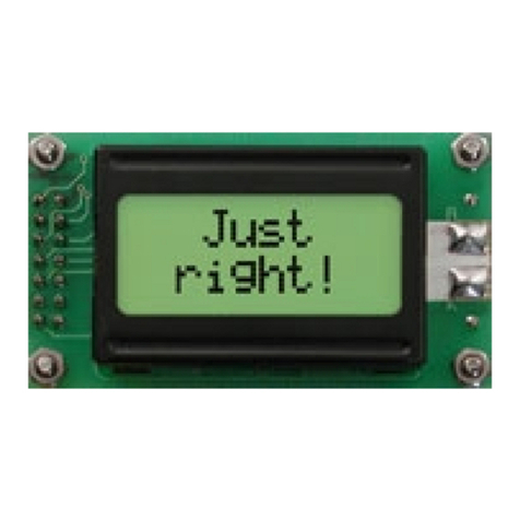
Figure 1: GLK24064-25/GLT24064 Display
The GLK24064-25/GLT24064 is an intelligent graphic liquid crystal display engineered to quickly and
easily add an elegant creativity to any application. In addition to the RS232, TTL and I2C protocols
available in the standard model, USB and RS422 communication models allow the GLK24064-
25/GLT24064 to be connected to a wide variety of host controllers. Communication speeds of up to
115.2kbps for serial protocols and 100kbps for I2C ensure lightning fast text and graphic display.
The simple command structure permits easy software control of many settings including backlight
brightness, screen contrast, and baud rate. On board memory provides thirty-two kilobytes of
customizable fonts and bitmaps to enhance the graphical user experience.
User input on the GLK24064-25 is available through a five by five matrix style keypad or a resistive touch
overlay on the GLT24064. Six general purpose outputs provide simple switchable five volt sources on
each model. In addition, a versatile Dallas One-Wire header provides a communication interface for up
to thirty-two devices.
The versatile GLK24064-25/GLT24064, with all the features mentioned above, is available in a variety of
colour, voltage, and temperature options to suit almost any application.

2
2Quick Connect Guide
2.1 Available Headers
Figure 2: GLK24064-25/GLT24064 Header Locations
Table 1: List of Available Headers
#
Header
Mate
Population
1
RS422 Terminal Block
16-30 AWG Wire
422 Model Only
2
Extended Communication/Power Connector
ESCCPC5V/BBC
Standard Model Only
3
Alternate Power Connector
PCS
422 and USB Models Only
4
Mini USB Connector
EXTMUSB3FT/INTMUSB3FT
USB Model Only
5
GPO Header
None Offered
All Models
6
DB9 Serial Header
CSS1FT/CSS4FT
Standard Model Only
7
Keypad/Touchpad
KPP4x4/Touch Panel
GLK/GLT Model Only

3
2.2 Standard Module
The standard version of the GLK24064-25/GLT24064 allows for user configuration of three common
communication protocols. First, the unit can communicate using serial protocol at either RS323 or TTL
voltage levels. Second, it can communicate using the Inter-Integrated Circuit connect, or I2C protocol.
Connections for each protocol can be accessed through the four pin Communication/Power Header as
outlined in the Serial Connections and I2C Connections sections below.
Recommended Parts
Figure 3: Extended Communication/Power
Cable (ESCCPC5V)
The most common cable choice for any standard Matrix Orbital
display, the Extended Communication/ Power Cable offers a simple
connection to the unit with familiar interfaces. DB9 and floppy power
headers provide all necessary input to drive your display.
Figure 4: Breadboard Cable (BBC)
For a more flexible interface to the GLK24064-25/GLT24064, a
Breadboard Cable may be used. This provides a simple four wire
connection that is popular among developers for its ease of use in a
breadboard environment.
2.3 Serial Connections
Serial protocol provides a classic connection to the GLK24064-25/GLT24064. The Extended
Communication/Power Cable is most commonly used for this set up as it provides connections for DB9
serial and floppy power cables. To place your board in Serial mode, adhere to the steps laid out below.
1. Set the Protocol Select jumpers.
RS232: Connect the five jumpers*in the 232 protocol box with the zero ohm jumper resistors
provided or an alternate wire or solder solution.
TTL: Connect the four jumpers*in the TTL protocol box.
*Note: Jumpers must be removed from all protocol boxes save for the one in use.

4
2. Make the connections.
a. Connect the six pin female header of the Extended Communication/Power Cable to the
Communication/Power Header of your GLK24064-25/GLT24064.
b. Insert the male end of your serial cable to the corresponding DB9 header of the Extended
Communication/Power Cable and the mate the female connector with the desired
communication port of your computer.
c. Select an unmodified floppy cable from a PC power supply and connect it to the power header
of the Extended Communication/Power Cable.
3. Create.
MOGD# or hyperterminal will serve to get you started, and then you can move on with your
own development. Instructions for these programs can be found below and a variety of
application notes are available at www.matrixorbital.ca/appnotes.
I2C Connections
A more advanced connection to the GLK24064-25/GLT24064 is provided by the I2C protocol setting. This
is best accomplished using a breadboard and the Breadboard Cable. Power must be supplied from your
breadboard or another external source. To dive right into your application and use the GLK24064-
25/GLT24064 in I2C mode, get started with the guidelines below.
1. Set the Protocol Select switches.
I2C: Ensure that the two I2C jumpers in the corresponding protocol box are connected while all
others are open.
2. Make the connections.
a. Connect the Breadboard Cable to the Communication/Power Header on your GLK24064-
25/GLT24064 and plug the four leads into your breadboard. The red lead will require power,
while the black should be connected to ground, and the green and yellow should be connected
to your controller clock and data lines respectively.
b. Pull up the clock and data lines to five volts using a resistance between one and ten kilohms on
your breadboard.
3. Create.
This time you're on your own. While there are many examples within the Matrix Orbital
AppNote section, www.matrixorbital.ca/appnotes, too many controllers and languages exist to
cover them all. If you get stuck in development, it is possible to switch over to another protocol
on the standard board, and fellow developers are always on our forums for additional support.

5
2.4 USB Module
The GLK24064-25-USB/GLT24064-USB offers a single USB protocol for easy connection to a host
computer. The simple and widely available protocol can be accessed using the on board mini B style
USB connector as outlined in the USB Connections section.
Recommended Parts
Figure 5: Mini USB Cable
(EXTMUSB3FT)
The External Mini USB cable is recommended for the GLK24064-25-USB
/GLT24064-USB display. It will connect to the mini-B style header on the
unit and provide a connection to a regular A style USB connector, commonly
found on a PC.
USB Connections
The USB connection is the quickest, easiest solution for PC development. After driver installation, the
GLK24064-25-USB/GLT24064-USB will be accessible through a virtual serial port, providing the same
result as a serial setup without the cable hassle. To connect to your GLK24064-25-USB/GLT24064-USB,
please follow the steps below.
1. Set the Protocol Select jumpers.
USB: The GLK24064-25-USB/GLT24064-USB offers USB protocol only. Model specific hardware
prevents this unit from operating in any other protocol, and does not allow other models to
operate in the USB protocol. Protocol Select jumpers on the USB model cannot be moved.
2. Make the connections.
Plug the mini-B header of your External Mini USB cable into your GLK24064-25-USB/GLT24064-
USB and the regular USB header into your computer USB jack. Additional power may be
required, especially for YG displays, and can be supplied to the Alternate Power Connector.
3. Install the drivers.
a. Download the latest drivers at www.matrixorbital.ca/drivers, and save them to a known
location.
b. When prompted, install the USB bus controller driver automatically
c. If asked, continue anyway, even though the driver is not signed
d. When the driver install is complete, your display will turn on, but communication will not yet be
possible.
e. At the second driver prompt, install the serial port driver automatically
f. Again, if asked, continue anyway
4. Create.
Use MOGD# or hyperterminal to get started, and then move on with your own development.
Instructions for these programs can be found below and a number of application notes are
available at www.matrixorbital.ca/appnotes.

6
2.5 RS422 Module
The GLK24064-25-422/GLT24064-422 provides an industrial alternative to the standard RS232
communication protocol. Rather than single receive and transmit lines, the RS422 model uses a
differential pair for each of the receive and transmit signals to reduce degradation and increase
transmission lengths. Power can be transmitted at distance to a -VPT module or supplied from the
immediate vicinity to a regular unit. RS422 signals are available in a six pin connector as described in the
RS422 Connections section.
RS422 Connections
The GLK24064-25-422/GLT24064-422 provides a robust RS422 interface to the display line. For this
interface, a series of six wires are usually screwed into the RS422 terminal block provided. An alternate
header is also available to provide local power to a regular unit. To connect to your GLK24064-25-
422/GLT24064-422, adhere to the steps laid out below.
1. Set the Protocol Select jumpers.
RS422: The GLK24064-25-422/GLT24064-422 offers only RS422 protocol and does not require
any jumper changes.
2. Make the connections.
a. Screw one wire; sized 16 to 30 on the American Wire Gauge, into each of the six terminal block
positions. When local power is supplied, a floppy cable may link to the alternate power header.
b. Connect the Vcc wire to the positive terminal of your power supply and the GND terminal to
the negative or ground lead to provide appropriate power as in Table 62.
c. Secure the A and B wires to your non-inverting and inverting output signals respectively, while
attaching the Z and Y wires to your inverting and non-inverting inputs.
3. Create.
In a PC environment, MOGD# or hyperterminal will serve to get you started. In addition, a
variety of application notes are available online in a number of different languages to aid in the
development of a host controller. Instructions for these programs can be found below and the
simple C# example at www.matrixorbital.ca/appnotes is a great first programming reference.

7
3Software
The multiple communication protocols available and simple command structure of the GLK24064-
25/GLT24064 means that a variety of applications can be used to communicate with the display. Text is
sent to the display as a character string, for example, sending the decimal value 41 will result in an 'A'
appearing on the screen. A single control character is also available. Commands are merely values
prefixed with a special command byte, 254 in decimal.
Table 2: Reserved Control Characters
Control Characters
10
Line feed / New line
Once the correct communication port is identified, the following communication settings can be applied
to communicate correctly with the GLK24064-25/GLT24064.
Table 3: Communication Settings
BPS
Data Bits
Parity
Stop Bits
Flow Control
19200
8
None
1
None
Finally, with a communication port identified and correctly setup simple text strings or even command
bytes can easily be transmitted to control your display.
3.1 MOGD#
The Matrix Orbital Graphic Display interface, MOGD#, is offered as a free download from
www.matrixorbital.ca/software/software_graphic. It provides a simple graphical interface that allows
settings, fonts, and bitmaps to be easily customised for any application.
While monotone bitmaps can easily be created in virtually any image editing program, MOGD# provides
an extensive font generation suite to stylize your display to any project design. In addition to standard
font wide modifications, character ranges can be specified by start and end values to eliminate unused
symbols, and individual glyphs can be modified with a double click. Finally, text spacing can be tailored
and a complete font library built with your Matrix Orbital graphic display.

8
Like uProject, MOGD# offers a scripting capability that provides the ability to stack, run, and save a
series of commands. The most basic function is the Send Numeric tool which is used to transmit a string
of values to the display to write text or execute a command.
Figure 6: MOGD# Command Example
Again, the clear screen command is sent to a connected display, this time using the MOGD# Send
Numeric function command style. Scripts can be run as a whole using the Play button from the toolbar
or as single commands by selecting Step; once executed it must be Reset. Before issuing commands, it is
a good idea to ensure communication with a display is successful using the autodetect button.
This program provides both a staging areas for your graphics display and a proving ground that will
prepare it for any application environment.
3.1 Firmware Upgrade
Beginning with revision 8.1, the firmware of the GLK24064-25/GLT24064 can be upgraded in the field.
Alternatively, the changes to the filesystem and subsequent commands can also be reverted by
downgrading the firmware to revision 8.0 using the same process.
All firmware revisions of the GLK24064-25/GLT24064 can be downloaded from
www.matrixorbital.ca/software/GLTSeries and installed using MOGD#.
3.2 Application Notes
Full demonstration programs and code are available for Matrix Orbital displays in the C# language from
Simple C# AppNote Pack in the Application Note section at www.matrixorbital.ca/appnotes. Difficulty
increases from beginner, with the Hello World program, to advanced, with the Dallas One-Wire
temperature reading application.
Many additional applications are available in a number of different programming languages. These
programs are meant to showcase the capability of the display and are not intended to be integrated into
a final design. For additional information regarding code, please read the On Code document also found
on the support site.

9
4Hardware
4.1 Standard Model
Extended Communication/Power Header
Figure 7: Extended Communication/Power Header
Table 4: Extended Communication/Power Pinout
Pin
Function
1
Vcc
2
Rx (SCL)
3
Tx (SDA)
4
Gnd
5
RTS
6
CTS
The Extended Communication/Power Header provides a standard connector for interfacing to the
GLK24064-25/GLT24064. Voltage is applied through pins one and four of the four pin
Communication/Power Header. Please ensure the correct voltage input for your display by referencing
the electrical specifications in Table 62 before connecting power. Pins two and three are reserved for
serial transmission, using either the RS-232/TTL or clocking data through the I²C protocol, depending on
what has been selected by the Protocol Select Jumpers. Pins five and six can be used for serial
transmission hardware flow control, and are ignored for I²C communications. The Molex 22-04-1061
style header used can be mated to a number of connectors.
Serial DB9 Connector
Figure 8: Serial DB9 Connector
Table 5: Serial DB9 Pinout
Pin
Function
2
Tx
3
Rx
5
Gnd
9
NC/Vcc*
The GLK24064-25/GLT24064 provides a DB-9 Connector to readily interface with serial devices using
EIA232 standard signal levels. It is also possible to communicate at TTL levels of 0 to +5V by setting the
Protocol Select Jumpers to TTL. As an added feature it is also possible to apply power through pin 9 of
the DB-9 Connector in order to reduce cable clutter. A standard male DB9 header will provide the
perfect mate for this connector.
*Note: Do not apply voltage through pin 9 of the DB-9 Connector AND through the Communication/Power Header
at the same time.

10
Power Through DB9 Jumper
In order to provide power through pin 9 of the DB-9 Connector you must connect the Power Through
DB-9 Jumper labelled R42, as illustrated below. This connection can be made using a zero ohm resistor,
recommended size 0603, or a solder bridge. The GLK24064-25/GLT24064 allows all voltage models to
use the power through DB-9 option, see the specifications in Table 62 for voltage requirements.
Figure 9: Power Through DB9 Jumper
Alternate Serial Header
Some advanced applications may prefer the straight two by five pin connection offered through the
optional Alternate Serial Header. This header offers power and communication access in a simple
interface package. The Alternate Serial Header may be added to the GLK24064-25/GLT24064 Standard
model for an added charge as part of a custom order. Please Contact sales for details.
Protocol Select Jumpers
The Protocol Select Jumpers provide the means necessary to toggle the standard GLK24064-
25/GLT24064 model between RS-232, TTL and I²C protocols. As a default, the jumpers are set to RS-232
mode with solder jumps on the RS232 jumpers. In order to place the display module in I²C mode you
must first remove the solder jumps from the RS232 jumpers and then place them on the I2C jumpers.
The display will now be in I²C mode and have a default slave address of 80, unless changed with the
appropriate command. Similarly, in order to change the display to TTL mode, simply remove the zero
ohm resistors from the RS232 or I²C jumpers and solder them to the TTL jumpers.
Hardware Lock
The Hardware Lock allows fonts, bitmaps, and settings to be saved, unaltered by any commands. By
connecting the two pads near the memory chip, designated as R13, with a zero ohm resistor the display
will be locked. This supersedes the data lock command and cannot be circumvented by any software
means. To unlock the display and make changes simply remove the jumper.

11
4.2 USB Model
Mini USB Connector
Figure 10: Mini USB Connector
Table 6: Mini USB Pinout
Pin
Function
1
Vcc
2
D-
3
D+
5
Gnd
The GLK24064-25-USB/GLT24064-USB comes with a familiar Mini USB Connector to fulfill both
communication and power needs. The standard Mini-B style header can be connected to any other USB
style using the appropriate cable. Most commonly used with a PC, this connection creates a virtual com
port that offers a simple power solution with a familiar communication scheme.
Alternate USB Header
Some advanced applications may prefer the straight four pin connection offered through the Optional
Alternate USB Header. This header offers power and communication access in a simple interface
package. The Optional Alternate USB Header may be added to the GLK24064-25-USB/GLT24064-USB for
an added charge as part of a custom order. Please use the Contact section to request more information
from the friendly Matrix Orbital sales team.
Alternate Power Connector
Figure 11: Alternate Power Connector
Table 7: Alternate Power Pinout
Pin
Function
1
Vcc
2
Gnd
3
Gnd
4
NC
The Alternate Power Connector provides the ability to power the GLK24064-25-USB/GLT24064-USB
using a second cable. The Tyco 171825-4 style header is particularly useful for connecting to an
unmodified floppy power cable from a PC power supply for a simple bench power solution.

12
4.3 RS422 Model
RS422 Header
Figure 12: RS422 Header
Table 8: RS422 Pinout
Pin
Function
1
Gnd
2
Rx (Y)
3
Inv Rx (Z)
4
Inv Tx (B)
5
Tx (A)
6
Vcc
The six pin RS422 interface header of the GLK24064-25-422/GLT24064-422 offers power and ground
connections as well as two differential pair communication lines. Regular and inverted lines are
provided for both receive and transmit signals. Power is supplied locally to the regular variant while the
–VPT can receive power over a distance. The Tyco 282834-6 style header is most suited to a simple wire
connection.
Alternate Power Connector
Figure 13: Alternate Power Connector
Table 9: Alternate Power Pinout
Pin
Function
1
Vcc
2
Gnd
3
Gnd
4
NC
The Alternate Power Connector provides the ability to power the GLK24064-25-422/GLT24064-422 using
a second cable. This is particularly useful for the regular module that is to be powered locally. The Tyco
171825-4 style header will fit a floppy power cable from a PC power supply for a simple bench power
solution.

13
4.4 GLK Model
Keypad Header
Figure 14: Keypad Header
Table 10: Keypad Pinout
Pin
Function
Pin
Function
1
Gnd
7
Column 1
2
Row 1
8
Column 2
3
Row 2
9
Column 3
4
Row 3
10
Column 4
5
Row 4
11
Column 5
6
Row 5
12
Gnd/Vcc*
To facilitate user input, the GLK24064-25 provides a Keypad Interface Connector which allows a matrix
style keypad of up to twenty-five keys to be directly connected to the display module. Key presses are
generated when a short is detected between a row and a column. When a key press is generated, a
character specific to that key press is automatically sent on the Tx communication line. If the display
module is running in I²C mode, the “Auto Transmit Keypress” function may be turned off to allow the
key presses to remain in the buffer so that they may be polled. The character that is associated with
each key press may also be altered using the “Assign Key Codes” command. The straight twelve pin
header of the Keypad Interface Connector will interface to a variety of different devices including the
Matrix Orbital KPP4x4 keypad.
*Note: The Ground / +5V pin is toggled by the jumper to the right of the keypad connector. Jump pads 1 & 2 for
+5V or 2 & 3 for GND.

14
4.5 GLT Model
Touch Screen
The GLT24064 facilitates user touch input in one of two distinct ways. Coordinate mode will report
events by supplying their exact position on the screen. Region mode will report events within defined
boundaries on the screen. Both modes are outlined below.
Coordinate Mode
In coordinate mode all touch events are reported using three
single byte values. First, the type of event is transmitted,
followed by the x and y coordinates of its position. Pressure
and drag thresholds must be exceeded for an event to be
registered. A low drag threshold will result in greater tracking
accuracy but transmits much more data to the host. Care
should be taken to find balance. This mode offers a great
degree of flexibility and creativity.
Table 11: Coordinate Mode Event Prefixes
Return Value
1
2
4
Touch Event
Press
Release
Drag
Region Mode
A simpler, keypad style alternative to coordinate mode,
region mode offers only a single byte for each touch event.
Unique regions are created by specifying a position, size, and
return values. A value corresponding to a specific region is
returned when an event occurs within its bounds. Events
outside of regions result in transmission of the value 255.
Regions can be deleted individually or collectively when no
longer needed. This mode allows quick and easy set up.
Table 12: Region Mode Event Responses
Return Value
Key Down
Key Up
Key Down
255
Touch Event
Press
Release
Drag
Out of Region
Other manuals for GLK24064-25
2
This manual suits for next models
5
Table of contents
Other Matrix Orbital Control Unit manuals
Popular Control Unit manuals by other brands

WAM
WAM R03 Series manual

INOXPA
INOXPA C-TOP+ operating instructions

FlowCon
FlowCon EVS Installation and operation instructions

DALEMANS
DALEMANS U-V6 instruction manual

Delta Electronics
Delta Electronics Ethernet Communication Module IFD9507 Applications manual

Honeywell Home
Honeywell Home HM700ADVALVE installation instructions