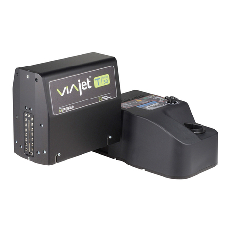
Matthews 8000+ Series User manual

Print Heads
8000+ Range
Technical Manual
Version: 1 Issue: 1
Order number 795 714.01
8000+ MINI 7v
8000+ MIDI 7v
8000+ MAXI 7v
8000+ MINI 16v
8000+ MIDI 16v
8000+ MAXI 16v
8000+ MINI 32v
8000+ MIDI 32v
8000+ MAXI 32v
Thank you for choosing a Matthews product
We hope that this manual will be one of the reasons for your continued confidence in Matthews
marking products. Therefore any suggestions which can lead to the increased quality of our
instruction manuals will be gratefully received.
Please send any suggestions to
this address:
MATTHEWS SWEDOT AB
Technical Documentation
Box 93
431 22 Mölndal
SWEDEN
www.matthewsmarking.com


Table of Contents
iiiPrint Heads 8000+ Range - Technical Manual - Version: 1 Issue: 1
Introduction
Conditions.........................................................................................1
Safety & Certification........................................................................1
About this manual.............................................................................2
History ..............................................................................................2
Overview
The 8000+ Range Print Heads.........................................................3
External Parts...................................................................................3
Print Head Compatibility...................................................................4
Pigmented Inks.................................................................................4
Dimensions.......................................................................................4
Installation
Adapting to Print Direction................................................................7
Positioning........................................................................................7
Using with the SX-32 and SX-32e Control Units..............................8
Using with the DOD•8400 and DOD•8400e Control Units................8
Using with the V84(e) and V84i Control Units..................................9
Reconditioning and In-Service-Rotation of Print Heads ...................10
Connecting to an Ink Supply Unit.....................................................12
Starting Up........................................................................................14
Appendices
Security Notices................................................................................17
Print Head Comparison Charts.........................................................17
Troubleshooting................................................................................18
User Notes........................................................................................20

1Print Heads 8000+ Range - Technical Manual - Version: 1 Issue: 1
Introduction
© Copyright Matthews Swedot AB, Mölndal 2006.
Conditions
Matthews Swedot AB reserves the right to change specifications in both the text and
illustrations without prior notice. The contents of this publication may not be copied,
either wholly or in part, without permission.
Matthews Swedot AB can not be held responsible for any direct, indirect, specific,
accidental or resultant injuries caused by a fault with the product, or by an error in the
accompanying documentation.
Safety & Certification
Matthews Swedot AB and Matthews Marking Products disclaim all responsibility
regarding the CE directive if this product is used, altered or installed in any way other
than described in this manual.
Please note the following warnings:
• Please read all instructions before using this product for the first time.
• We do not recommend the use of extension cables.
• Cables and tubes must not be subjected to strain or tension.
• Bends in cables should be no less than ten times the diameter of the cable.
• Ensure that this product is not placed anywhere where the cable can be stood on or
snagged.
• Do not attempt to open the cover of this product. Internal parts cannot be serviced
by the user.
• Never point the nozzle end of a print head at yourself or another person.
• All chemicals, even ink, may present unknown health hazards, and should be
treated with caution. Please refer to the Material Safety Data Sheet for further
information.
• To avoid ink and cleaner fluid spill, ensure that all tubes (including connections
and joints) are mounted so that they can not be damaged or inadvertantly
detached.
• Never use sharp or pointed tools when cleaning or replacing the print head.
• Disconnect the power to the printer and call in qualified personnel under the fol-
lowing conditions:
The power cable or plug is damaged or worn • Liquid has been spilled on the
Contact details - Manufacturer
Matthews Swedot AB
Möbelgatan 4
431 33 Mölndal
Phone: +46 (0)31 338 79 00
Fax: +46 (0)31 845 117
USA
Matthews Marking Products
6515 Penn Avenue
Pittsburgh, PA 15206
Phone: +1 412 665-2500
Fax: +1 412 665-2550
China
Kenuohua Matthews
Building C, Jinri Science Park
No.26 Jinyuan Road
Daxing Industrial Development Zone
Beijing 102600
Phone: +86 10 88796525
Fax: +86 10 88796526
Print Heads 8000+ Range - Technical Manual - Version: 1 Issue: 12
INTRODUCTION
printer • Rain or water has got into the printer • The printer is not functioning cor-
rectly despite the user following the instructions for use • You have dropped this
product or the casing has been damaged. • This product is not functioning cor-
rectly and requires service.
About this manual
This manual gives technical information which is particular to print heads in the
Jet•A•Mark 8000+ range. These are:
•8000+ MINI 7v • 8000+ MINI 16v • 8000+ MINI 32v
•8000+ MIDI 7v • 8000+ MIDI 16v • 8000+ MIDI 32v
•8000+ MAXI 7v • 8000+ MAXI 16v • 8000+ MAXI 32v
This manual does not cover information related to other products, such as how to
connect a print head to a specific control unit. For this and more information related
to other products, please see the documentation received with those products.
The 8000 MINI 7v IP65, V3 print head is covered in the Special Print Heads docu-
mentation. Please contact your dealer for more information.
User information for these print heads is covered in the User Guide received with
your print head.
History
The following table shows which Technical Manual should be used with which print
head:
Print Head
model Print Head
serial number
Manual
version
numbera
a. Shown on the Contents page.
Update information
8000+ print
heads 32v - 3900 and above
16v - 5250 and above
7v - 1700 and above
V1 I1 First release

3Print Heads 8000+ Range - Technical Manual - Version: 1 Issue: 1
Overview
The 8000+ Range Print Heads
The Jet•A•Mark 8000+ range comprises of the MINI, MIDI and MAXI print head
types. Each type has different printing characteristics with respect to print resolution
(drop size) where MINI print heads are used for high resolution printing and produce,
therefore, small drops, MAXI heads print at a low resolution using large drops and
MIDI heads have printing characteristics falling in the middle of the two.
Each print head type is available in three models: a 7 valve print head, a 16 valve
print head and a 32 valve print head, one for each maximum print height.
See “Print Head Comparison Charts” on page 17 for tables showing the differences
between the print heads.
External Parts
8000+ MINI 7v
8000+ MIDI 7v
8000+ MAXI 7v
8000+ MINI 16v
8000+ MIDI 16v
8000+ MAXI 16v
8000+ MINI 32v
8000+ MIDI 32v
8000+ MAXI 32v
Connection to control unit
Nozzles (ink out)
Printout activator
bracket
Mounting clamp
Ink connector
Cleaner fluid connector
(16v and 32v heads only)
Flush valve
Print target guide plate

Print Heads 8000+ Range - Technical Manual - Version: 1 Issue: 14
OVERVIEW
Print Head Compatibility
The 8000+ print heads are fully compatible with control units used for 8000 print
heads. An 8000+ print head can be used to replace an existing 8000 print head that is
in operation. There is no need to make any changes in the control unit and its settings.
Pigmented Inks
Failure to correctly use pigmented inks, as described below, can cause
permanent damage and void the print head’s warranty.
All maintenance information contained in this manual is only applicable when using
non-pigmented inks.
If an 8000+ print head is to be used with pigmented inks a Matthews CISU
(Circulating ink Supply Unit) must also be used. The operation and maintenance
information provided in the CISU’s Operator manual must be adhered to.
Dimensions
8000+ range, 7v - Approximate weight, excluding clamp: 0,9kg (2lb.)
0,5mm (0,02in)*
190mm (7,5in)
328mm (12,9in) 400mm (15,7in)**
380mm (15,0in)**
280mm (11,0in)**
87,5mm (3,4in)
123mm (4,8in)
42,7mm (1,7in)
30mm
(1,2in)
55mm
(2,2in)
D 18mm
(0,7in)
Distance from nozzle plate to outer edge
of print target guide plate.
Approximate distance.
Approximate minimum space necessary.
*
**
***
450mm (17,5in)***

OVERVIEW
5Print Heads 8000+ Range - Technical Manual - Version: 1 Issue: 1
8000+ range, 16v - Approximate weight, excluding clamp: 1,4kg (3lb.)
8000+ range, 32v - Approximate weight, excluding clamp: 2,2kg (4,8lb.)
380mm (151,0in)**
0,5mm (0,02in)*
190mm (7,5in)
328mm (12,9in) 490mm (19,3in)**
280mm (11,0in)** Cleaner
Ink
400mm (15,7in)**
123,5mm (4,9in)
159mm (6,3in)
44mm (1,7in)
30mm
(1,2in)
55mm
(2,2in)
D 18mm
(0,7in)
Distance from nozzle plate to outer edge
of print target guide plate.
Approximate distance.
Approximate minimum space necessary.
*
**
***
450mm (17,5in)***
380mm (151,0in)**
0,5mm (0,02in)*
190mm (7,5in)
328mm (12,9in) 490mm (19,3in)**
280mm (11,0in)** Cleaner
Ink
400mm (15,7in)**
187,5mm (7,4in)
223,4mm (8,8in)
44mm (1,7in)
30mm (1,2in)
55mm (2,2in)
D 18mm (0,7in)
Distance from nozzle plate to outer edge
of print target guide plate.
Approximate distance.
Approximate minimum space necessary.
*
**
***
450mm (17,5in)***

7Print Heads 8000+ Range - Technical Manual - Version: 1 Issue: 1
Installation
See also “Troubleshooting” on page 18.
Adapting to Print Direction
Each 8000+ range print head is equipped with a print target guide plate which is used
to partly prevent the newly printed dots being smudged by the print head itself and
partly to flatten uneven surfaces.
Using a size 10 torx driver, mount the guide plate according to the following:
Positioning
Follow these guidelines when installing 8000+ range print heads.
• Position the print head so that it is as close as possible to the print target during
printout. The maximum print distance is 25mm (1in)1.
• The ink supply tube should be made as short as possible and no longer than 15m
(50ft).
• To avoid ink and cleaner fluid spill, ensure that all tubes (including connections and
joints) are mounted so that they can not be damaged or inadvertently detached.
• Please see “Print Head Comparison Charts” on page 17 for the maximum print
target speed.
• Make sure that the print head is not positioned so that the print target can knock
against it. It may be necessary to mount a guard rail so that the print target cannot
change its path.
1. This distance is dependant on the print speed. The higher the speed the closer the
print head needs to be to the print target.
The arrows show the direction in
which the print target shall pass
in front of the print head.
Print head
Print
target
View from above

Print Heads 8000+ Range - Technical Manual - Version: 1 Issue: 18
INSTALLATION
Using with the SX-32 and SX-32e Control Units
Note that the standard Matthews warranty is void if the 8000+ range print heads are
used together with any other control units than the following:
DOD•8400/DOD•8400e, SX-32/SX-32e, SX-32i, V84/V84e, or V84i
For more information see the documentation received with the applicable control
unit.
At the SX-32(e) control unit, select a print head configuration according to the
following. The documentation received with the SX-32(e) control unit, explains how
this is done.
Please see “Print Head Comparison Charts” on page 17 for information on
installation settings.
Using with the DOD•8400 and DOD•8400e Control Units
Note that the standard Matthews warranty is void if the 8000+ range print heads are
used together with any other control units than the following:
DOD•8400/DOD•8400e, SX-32/SX-32e, SX-32i, V84/V84e, or V84i
Please follow these guidelines when using the 8000+ range print heads. For more
information see the documentation received with the control unit.
• Up to four 8000+ range print heads or a maximum of 32 valves can be connected to
the control unit to print messages1.
• The control unit’s driver board settings must be adapted to the total number of
nozzles connected, the nozzle grouping (print head nozzles) and the print head type
used. In this case the print head type to be selected is:
1. All print heads must have the same Print Direction setting.
Number of print head valves*
Print head type*
Number of print heads
* Shown on the print head serial number label

INSTALLATION
9Print Heads 8000+ Range - Technical Manual - Version: 1 Issue: 1
The Technical Manual, received with the control unit, explains how this is done.
Please see “Print Head Comparison Charts” on page 17 for information on
installation settings.
Using with the V84(e) and V84i Control Units
Note that the standard Matthews warranty is void if the 8000+ range print heads are
used together with any other control units than the following:
DOD•8400/DOD•8400e, SX-32/SX-32e, SX-32i, V84/V84e, or V84i
• Up to four 8000+ range print heads or a maximum of 32 valves can be connected to
the V84(e)/V84i control unit to print messages.
At the control unit, select a print head configuration according to the following. The
documentation received with the control unit, explains how this is done.
For this print head Select this setting
8000+ MINI 7v 8000Mini.7v
8000+ MINI 16v 8000Mini.16v
8000+ MINI 32v 8000Mini.32v
8000+ MIDI 7v 8000Midi.7v
8000+ MIDI 16v 8000Midi.16v
8000+ MIDI 32v 8000Midi.32v
8000+ MAXI 7v 8000Maxi.7v
8000+ MAXI 16v 8000Maxi.16v
8000+ MAXI 32v 8000Maxi.32v
Number of print heads of each typea
a. Never connect different print head types to the control unit.
7 Valve 16 Valve 32 Valve Select this settingb
b. For the V84(e) only. For further information regarding the V84i refer to the Technical/
Protocol manual.
17, 7
27,7
2 1 16, 7, 7c
c. The option 7, 7, 16 can also be selected depending on the set up. Refer to the control
unit manual for further information.
4 7, 7, 7, 7
116
2 16, 16
132

Print Heads 8000+ Range - Technical Manual - Version: 1 Issue: 110
INSTALLATION
Please see “Print Head Comparison Charts” on page 17 for information on
installation settings.
Set the Print Direction for each printhead as required. Refer to the control unit’s
technical manual for further information.
Reconditioning and In-Service-Rotation of Print Heads
The following recommendations are provided to ensure correct operation of print
heads that have been inactive for six months.
Reconditioning a Print Head prior to Installation
If the stamp on the print head package indicates that it was produced more than six
months prior to the actual date, it is strongly recommended that the print head is
reconditioned before it is put in to operation.
Poor print quality, uneven ink drops during printout, and slight leakage from the
nozzles (weapage) can occur if print heads are not correctly prepared, as described
below.
Please follow the instructions below if a print head has been inactive for more than
six months.
Safety glasses and solvent resistant gloves must be used when contact with ink or
solvent liquids is possible. If cleaning solution comes in contact with skin wash it
immediately. If contact is made with eyes or mouth, wash them for at least 15 minutes
and seek medical advice.
The following procedure sets the printer up to print a message approximately seven
times a minute.
1. Connect cleaner fluid, from an ink-supply unit, to the print head’s ink-supply
line. See “External Parts” on page 3.
2. Set the ink pressure according to “Print Head Comparison Charts” on page 17
and turn the ink-supply-unit ON.
3. Use the print head’s external flush valve and flush the print head for about 5
seconds.
4. Connect the print head to a control unit.
5. If the print head has an internal three-way-valve set it to Ink. Use the control unit
to set it to Ink.
Note: The seven valve print heads and the sixteen valve basic do not have an

INSTALLATION
11Print Heads 8000+ Range - Technical Manual - Version: 1 Issue: 1
internal three-way-valve.
6. Create a message consisting of 10 characters. Select a font that will use all of the
print head’s nozzles.
7. Set the following parameters for the respective control units listed below.
8. Place an object in front of the photocell (printout activator) so that printout is
continuously activated.
9. Start printing and allow the print head to run for an hour. Once complete the
print head will be ready for delivery/installation.
In-Service-Rotation of Spare Print Heads
In installations where spare print heads are kept in stock, the spare heads should be
rotated in-service, every six months. This will ensure correct operation of the print
heads when put in service.
SX-32 control unit
Printer settings Speed source
Target speed
Print height
Spacing/Dot size
Manual
15,0m/min. (49,2ft/min.)
Maximum
Within the recommended range. See
“Print Head Comparison Charts” on
page 17.
Trigger settings Trigger mode
Terminate
Skip trigger
External
Not applicable
0 (zero)
Mark settings Multiple mark
Mark gap
Mark length
0 (zero)
0 (zero)
2000 mm (78,7 inches)
DOD•8400 and DOD•8400e control units
Config/Limit Terminate
Mark gap
Max mark
Max trig
Not applicable
2000 mm (78,7 inches)
Off
Off
Install/Manual Encoder
Speed
Trigger
Distance
Height
None
15,0 m/min. (49,2ft/min.)
External
0
100%
Message settings Spacing/Dot size Within the recommended range. See
“Print Head Comparison Charts” on
page 17.

Print Heads 8000+ Range - Technical Manual - Version: 1 Issue: 112
INSTALLATION
If spare print heads are rotated every six months, there will be no need to recondition
them, as described above. The spare heads will simply require flushing with cleaner
and ink before use, as described under “Starting Up” on page 14.
Before removing a print head from service its ink lines and nozzles must be flushed
with cleaner.
Connecting to an Ink Supply Unit
Safety glasses and solvent resistant gloves must be used when contact with ink or
solvent liquids is possible. If cleaning solution comes in contact with skin wash it
immediately. If contact is made with eyes or mouth, wash them for at least 15 minutes
and seek medical advice.
Note that the standard Matthews Swedot warranty is void if the 8000+ range print
heads are used together with any other than Jet-A-Mark ink supply units.
For procedures relating to a specific ink supply unit, please see the documentation
received with your unit.
General Information
• Use the Matthews 2x1 litre HP ink supply system or FPS (Basic or Advanced) for
ink delivery.
• All 8000+ range print heads are run in with the ink type specified by the customer.
Damage will occur and the warranty will be void if the head is used with any other
ink type. Please contact your dealer if you wish to change ink types.
• When flushing and cleaning, use only cleaner fluid which is suited to the ink type
being used.
• Please see “Print Head Comparison Charts” on page 17 for information on the
nominal ink pressure range for the applicable print head.
• Do not use pressurised (factory) air.
Ink connector (black)
Cleaner fluid connector (yellow)*
Flush valve (white)
*The 8000+ range, 7v head does not have a cleaner fluid connector

INSTALLATION
13Print Heads 8000+ Range - Technical Manual - Version: 1 Issue: 1
Ink Tube Recommendations
The choice of tubing, between the print head and ink supply unit, is dependant on the
type of installation according to the following:
Ink Filtering Recommendations
Under normal printing situations the ink supply unit will take care of any ink filtering
needs and extra filtration is therefore not necessary. An exception is when 1700A ink
is being used. This ink requires that a standard (CS marked) filter is used between the
ink supply unit and the print head. Please contact your dealer to order the filter.
For information relating to the ink supply unit, please see the documentation received
with your unit.
Type of installation Choice of tubing Diameter: mm (inches)
Normal printing frequency and
ink usage. Standard Internal: 3,2 mm (0,125 in)
External: 6,4 mm (0,25 in)
More than one print head
connected to a single ink supply
unit.
Continuous or barcode printing.
High capacity Internal: 6,4 mm (0,25 in)
External: 9,5 mm (0,375 in)
8000+ head
Standard
filter
Always replace a filter after 300 litres
(80 US gallons - 66 UK gallons) of ink has passed
through it or after 6 months of use.
1700A ink
Ink supply unit

Print Heads 8000+ Range - Technical Manual - Version: 1 Issue: 114
INSTALLATION
Starting Up
Safety glasses and solvent resistant gloves must be used when contact with ink or
solvent liquids is possible. If cleaning solution comes in contact with skin wash it
immediately. If contact is made with eyes or mouth, wash them for at least 15 minutes
and seek medical advice.
The 8000+ print heads must be correctly prepared as described below before using
them for the first time. Failure to correctly prepare a print head can lead to permanent
damage and void its warranty.
1. Connect the print head to a control unit.
2. Get a bottle of ink and a bottle of cleaner.
3. Get an ink-supply-unit and mount both the ink bottle and the cleaner bottle in to
it.
If the print head has a cleaner supply line continue from Step 4, otherwise
continue from Step 5.
4. Connect the cleaner supply, from the ink-supply-unit, to the print head’s cleaner-
supply-line. The supply lines to the print head are clearly labelled: Cleaner and
Ink respectively.
4.1. Use the control unit to switch the print head’s internal three-way-valve to
Cleaner. Refer to the control unit’s manual as necessary.
4.2. Turn the ink-supply-unit ON and flush the print head with approximately
0,1 Litre of cleaner. Use the print head’s two way flush valve, as shown, to
flush the head.
4.3. Use the control unit and set the print head’s internal three-way-valve to Ink.
5. Connect the cleaner supply, from the ink-supply-unit, to the print head’s ink-
supply-line.
6. Turn the ink-supply-unit ON and use the print head’s flush valve to flush the
print head with approximately 0,2 Litre of cleaner fluid.
Ink and cleaner supply lines. (Cleaner
supply line only on certain models) Flush valve

INSTALLATION
15Print Heads 8000+ Range - Technical Manual - Version: 1 Issue: 1
7. Connect the ink supply, from the ink-supply-unit, to the print head’s ink-supply-
line.
8. Flush the print head using its flush valve. Stop when ink can be seen exiting the
flush valve.
9. Use the flush function in the control unit and flush the print head’s nozzles with
ink. Place a piece of cardboard in front of the nozzles while they are flushing, to
catch the ejected ink. Refer to the control unit’s manual for further information
regarding the use of the flush function, if required.
The print head is now ready for operation.
This manual suits for next models
9
Table of contents
Other Matthews Printer Accessories manuals