Maxair CA-DLC-CAPR-36 User manual

P/N 01023649 Rev B Page 1
DLC Cus
(Disposable Lens Cus)
User Instructions
Intended Use
The MAXAIR DLC is to be donned with a MAXAIR CAPR®
Helmet and a MAXAIR Filter Cartridge.
CAPR DLC Systems lter aerosolized and droplet particulates.
DLCs are designed for single use applications.
O.N. 2365-02SM
O.N. 2365RB-02SM*
(01031316)
Small-Medium
O.N. 2365-02ML
O.N. 2365RB-02ML*
(01031291)
Medium-Large
*RB indicates plastic
reusable dispensing box vs.
standard cardboard.
1. 2081-03 Helmet with
2051-07 SnapOn Cage
removed, 2071-08 Liner, and
2590-05 Power Cord
2. 2167-10 Filter Cartridge*
3. 2061-08 Filter Cover
Cap (FCC)
4. 2500-36TSC Battery** 5. 2000-76 Battery Belt
6. 2600-01 Battery Charger*** 7. 2365-02 DLC ML & SM
Materials
DLC Lens is PETG
DLC Cu is Polyurethane
* Alternate Filters include the 2180-05, 2166-10, and 2164-10
** Alternate Batteries include the 2500-37TSC
*** Alternate Charger includes the 2602-01.
5 64
32
7
Symbol Denitions
Warning, Caution, or Note
Order Number Part Number
!
O.N. P/N
1
Standard CA-DLC-CAPR-36 System1with DLC
MAXAIR Recommended System Temperature Limits:
Use/Handling: 0oC to 540C at a maximum 80% Relative Humidity.
Charging: 0oC to 450C at a maximum 80% Relative Humidity.
Storage: 0oC to 350C at a maximum 80% Relative Humidity.
All MAXAIR Systems, components, and disposables are latex free.
Regulatory
NIOSH
Specications
WARNING
Failure to follow User Instructions P/N 03521015 and the instructions
contained herein may be hazardous to the user’s health.
Use only if package is received unopened and contents are
undamaged. If damage is noted, contact the shipper for replacement
or repair.
Prior to using any MAXAIR® System or component, be sure to be
familiar with the system’s NIOSH approved conguration.
DO NOT use if any component is damaged. If any components are
damaged or contaminated and therefore unt for safe and eective
use, they should be replaced immediately.
Only trained and experienced personnel who have read and
understand the User Instructions should use MAXAIR Products.
The institution using this product in any application is responsible
for determining the appropriateness of this equipment relative to
regulatory requirements. Bio-Medical Devices Intl, Inc. does not
recommend the appropriate systems for a particular institution or
facility.
Use only MAXAIR Systems/ NIOSH approved compatible
components.
NOT for use in atmospheres immediately dangerous to life or health
(IDLH), and atmospheres containing less than 19.5% oxygen, or
more than 25% oxygen.
Flammability Level I: fabric may burn if exposed to open ame.
Follow current local regulations governing biohazard waste to safely
dispose of single use MAXAIR Products.
If you need more information, contact your BMDI Sales
Representative, or call BMDI customer service at 1-800-443-3842.
!
CAUTION
Before use, thoroughly read MAXAIR CAPR P/N 03521015 User Instruction (received with all CAPR Helmets and
available at www.maxair-systems.com.
!

P/N 01023649 Rev B Page 2
DLC Cus
(Disposable Lens Cus)
User Instructions
WARNING
Always start with the ML size unless the wearer has a very small head size.
The DLC Cu side must face to the inside of the Helmet; the Lens side must face to the outside of the Helmet.
NOTE
This shows the 2081-03 Helmet with 2061-08 FCC; it is similar for the 2083-03 Helmet and 2061-04A Hard Hat.
Assembly
1. Secure the Helmet/FCC in your
lap with the Helmet front facing
up, and the top of the Helmet
facing in towards you.
4. With thumbs pressing the DLC
against the FCC front white
foam strip, press and slide your
thumbs down each DLC side
until you can grasp each end of
the DLC at the Flappers.
3. Ensure the DLC Front
alignment hole is
centered on the Front
Turn Clip.
2. Align the FCC front TurnClip horizontally,
snap the DLC Front Alignment Hole over
the TurnClip, then position the TurnClip
vertically to lock the DLC in place.
5. Pull each DLC side down
towards the Helmet back and
tightly against the white foam
strip, position each side DLC
Mounting Hole as centered as
possible over each respective
FCC side Mounting Post.
6. Press the DLC tightly against the
FCC to secure the Mounting Hole
onto each Mounting post. (You
will hear an audible “click” when
properly secured).
Assembly Steps 4-6 Option A
P/N 01023649 Rev B Page 3
DLC Cus
(Disposable Lens Cus)
User Instructions
WARNING
If conditions 1 and 2 both are not achieved, switch to the other size DLC and repeat Donning steps 1 through 6 above.
Condition 1: Ensure the DLC Flappers are
away from the Lens, positioned perpendicular to
your temples, and in front of the FCC Side Tabs.
DLC Flappers
FCC Side Tabs
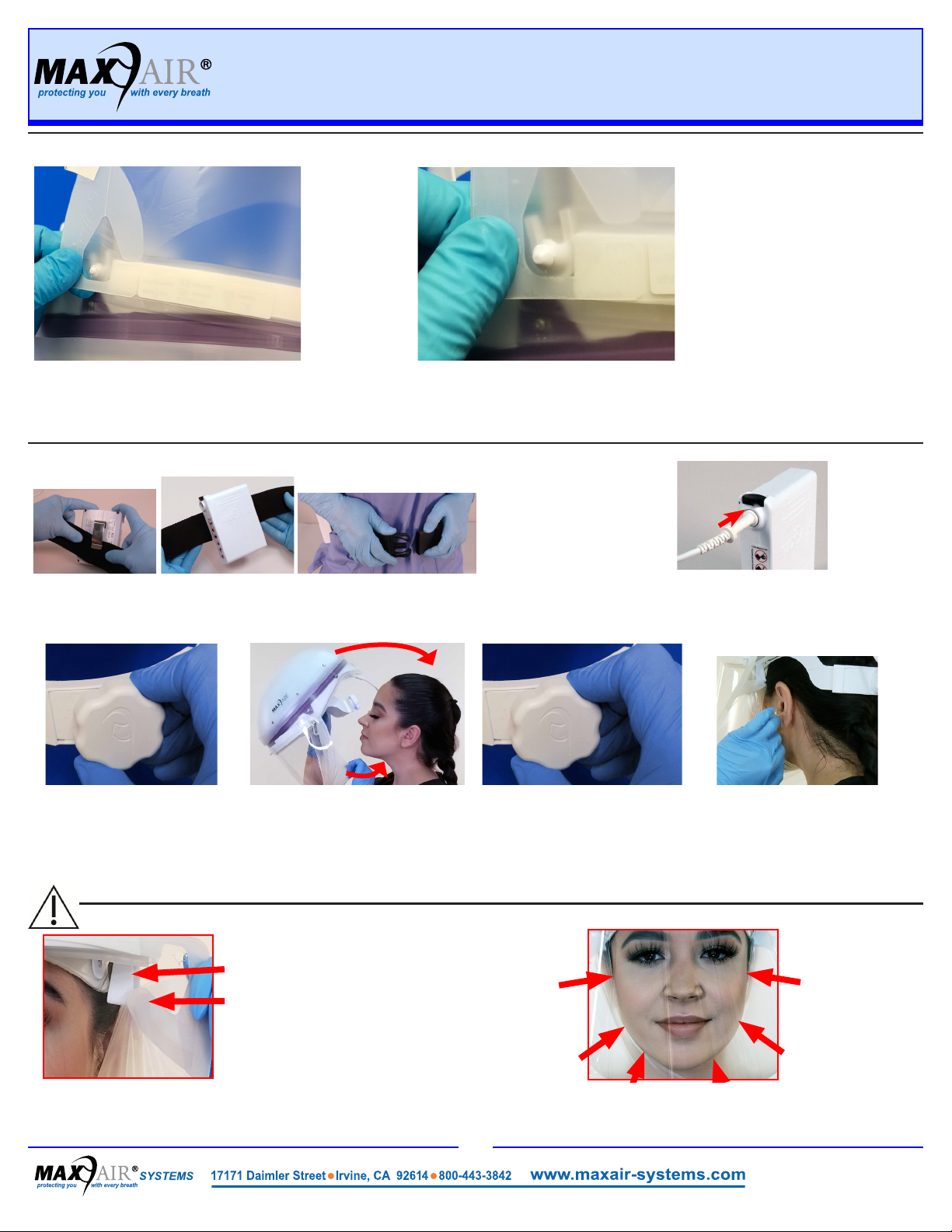
1. Place the Belt top edge under the Battery Clip, with the Belt
fully under and up to the Clip top. Place the belt around the
waist with the battery near the side-back of the right hip.
Donning
2. Connect the Helmet Power Cord to the Battery. Push
the Power Cord Connector into the Battery Receptacle
until the Secure Connection audibly clicks.
6. Slide your ngers between Cu
and face from temples down
under the chin to pull the DLC
Flappers away from the lens,
and properly position the cu.
4. Hold the Helmet at the rear
headband, pull the DLC Cu
down, place your chin into the
DLC Cu. Pull the Helmet over
and down on your head.
3. Loosen the rear
Headband Adjustment
Knob by turning it
counterclockwise.
5. Tighten the rear
Headband Adjustment
Knob (clockwise). Ensure
a tight but comfortable t
for all activities.
4. The DLC Front Alignment Hole secured,
grasp one DLC end by the Flapper and
stretch it tauntly until that side Mounting
Hole is over that side Mounting Post.
5. That side DLC Mounting Hole centered over the FCC side
Mounting Post, press the DLC down fully onto the Mounting
Post. An audible click indicates the DLC is properly around
and down securely on the Mounting Post.
6. Repeat steps
4. and 5. for
the other side.
Condition 2: Ensure slight tension on the cu is felt continuously while
sliding the index or rst nger between the cu and the face all along
the chin and up to the temples, from the right side of the face to the left.
Assembly Steps 4-6 Option B

P/N 01023649 Rev B Page 4
DLC Cus
(Disposable Lens Cus)
User Instructions
WARNING
Refer to Section 9, User
Instruction Manual P/N
03521015, for details on
proper use of chargers
and for charging
batteries.
4. Disconnect the Battery Belt
from around the waist by un-
snapping the buckle.
5. With the Charger connected to the mains wall power,
push the Charger Cord Connector into the Battery
Receptacle until it is fully seated.
2. Grasp both side DLC Flappers and
lift out and away from the FCC Side
Attachment Posts.
3. Continue to pull the DLC forward o the front
TurnClip and away from Helmet.
Dispose of the DLC according to your
institution’s protocol for contaminated waste.
Disassembly
1. Align FCC front TurnClip
horizontally.
Dong
1. Loosen the rear Headband
Adjustment Knob (turn
counterclockwise).
2. Pull the DLC Cu away from
the chin and lift the Helmet up,
forward, and o the head.
3. Disconnect Battery from the Helmet -
push Secure Connection Button down,
pull Cord Connector out, release Button.
CAUTION
If the Helmet is not secure and comfortable, it may be necessary to change the Height Adjustment,
which raises and lowers the rear headband and the Helmet angle with respect to the head, and
properly positions the DLC Lens from the chin. Together with the Adjustmont Knob they optimize a
secure and comfortable t and proper positioning for easy visualization of the LED Safety Status
Indicators. To adjust, unsnap the Height Adjustment tabs on each side of the Helmet Liner and
reposition upward or downward. .
Be sure to have both Height Adjustment tabs in the same position.
≤ 1/2
Inch
(~1.25 cm)
CAUTION
Optimum setting is achieved
when the helmet is secure on the
head for all movements required
and the front headband is within
1/2 inch of the eyebrows to allow
good visualization of the LED
Safety Status Indicators in the
upper peripheral vision.
7. Position the Helmet so that the front headband is within ½ inch of the eyebrows and
the rear headband is resting under the occipital bone above the vertebrae on the
neck, and then tighten the Adjustment Knob clockwise to ensure the most secure t
of the helmet on the head for all activities. Do not over tighten to cause discomfort.
Other Maxair Protection Device manuals


