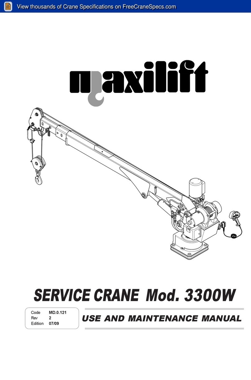
maxilift M50 Series User manual

Mod. M50
Code MD.0.136GB Rev 0Edition 03/07
USE AND MAINTENANCE MANUALUSE AND MAINTENANCE MANUAL
USE AND MAINTENANCE MANUAL

Fill in the space below with the required crane identification data.
Codefilling example: M50.2H ELH
SERIAL NUMBER: ......................
MANUFACTURING YEAR: ...................
Mark the box regarding the accessories supplied with the crane
ACCESSORIES SUPPLIED WITH THE CRANE
Description YES NO
Electrical winch
Manualwinch
Stabilizer
Back load attachment
Quick fitting kit
PRELIMINARYINFORMATION
Operator’sandMaintenanceManual ofMAXILIFT M50 truck loader.
Manualcode: MD.0.136 GB
This manual is valid starting from serial no: ....................
Manufacturer:NEXT HYDRAULICS S.r.l.
ViaMediterraneo6,Boretto(RE)-ITALY
Inthis manualthe word “Manufacturer” isreferred to“NEXT HYDRAULICS S.r.l.”.
Listof documentationsupplied along with the loader:
¾Operator’sand Maintenance Manual(for the enduser)
¾InstallationManual (forthe installerand the end user)
ATTENTION
Always carefully read this manual before operating the loader. Most of the accidents occurred during
operations are caused by omission of elementary precautions and non fulfilment of the safety instructions.
Many accidents can be avoided when their causes are well known and relevant adequate
countermeasures are previously taken.
M50 2 H E L H
.
M50 2
.

INDEX
1 FOREWORD -------------------------------------------------------------------------------------------- Page--1
1.1 Remarks ------------------------------------------------------------------------------------------------“ ----- 1
2 HOW TO CONSULT THE MANUAL------------------------------------------------------------------- “----- 1
2.1 Instructions ------------------------------------------------------------------------------------------------“ ----- 1
3 CRANEIDENTIFICATION-------------------------------------------------------------------------------- “----- 2
3.1 Identification data--------------------------------------------------------------------------------------------“ ----- 2
3.3.1 Nameplate description ------------------------------------------------------------------------------------“ ----- 2
3.2 Main cranecomponents identification------------------------------------------------------------------“ ----- 2
3.3 Crane composition ------------------------------------------------------------------------------------------“ ----- 3
3.4 Accessories ------------------------------------------------------------------------------------------------“ ----- 4
3.4.1 Winch ------------------------------------------------------------------------------------------------“ ----- 4
3.4.2 Stabilizers ------------------------------------------------------------------------------------------------“ ----- 4
4 COMMISSIONING----------------------------------------------------------------------------------------- “ ----- 5
4.1 Check list before the first commissioning -------------------------------------------------------------“ -----5
4.2 Daily check list ----------------------------------------------------------------------------------------------“ ----- 5
4.3 CE Certification ----------------------------------------------------------------------------------------------“ ----- 5
5 GENERAL SAFETYRULES ----------------------------------------------------------------------------- “ ----- 5
5.1 Rules concerningpersons---------------------------------------------------------------------------------“ ----- 5
5.2 Rules concerning the crane-------------------------------------------------------------------------------“ -----5
5.3 Rules concerning safety in the traffic -------------------------------------------------------------------“ ----- 6
6 OPERATING INSTRUCTIONS -------------------------------------------------------------------------- “ ----- 7
6.1 Daily check list ----------------------------------------------------------------------------------------------“ ----- 7
6.2 Loaderclassification and properusage ----------------------------------------------------------------“ ----- 7
6.3 Improperusage ----------------------------------------------------------------------------------------------“ ----- 7
6.4 General attentions ------------------------------------------------------------------------------------------“ ----- 7
6.5 Ten basicrules forthe safeloader operator-----------------------------------------------------------“ -----9
6.6 Instructions for use -----------------------------------------------------------------------------------------“ ----- 9
6.6.1 Thrustslewing system -------------------------------------------------------------------------------------“ ---- 10
6.6.2 Crank slewing system -------------------------------------------------------------------------------------“ ---- 10
6.6.3 Hydraulicslewing system ---------------------------------------------------------------------------------“ ---- 11
6.6.4 Boom lifting system by mechanic strut ----------------------------------------------------------------“ ---- 11
6.6.5 Boom lifting system by hydraulic cylinder ------------------------------------------------------------“ ---- 12
6.6.6 Two manualextensions boom system -----------------------------------------------------------------“ ---- 13
6.6.7 Boom system with 1st hydraulic and 2nd manual extensions --------------------------------------“ ---- 14
6.6.8 Hydraulic operating system by hand pump for lifting cylinder ------------------------------------“ ---- 15
6.6.9 Hydraulic operating system by hand pump for lifting and extension cylinders ---------------“ ---- 16
6.6.10 Hydraulic operating system by hand pump for extension cylinder ------------------------------“ ---- 17
6.6.11 Electro-hydraulic operatingsystem bypower unit with one function
for lifting cylinder--------------------------------------------------------------------------------------------“ ---- 17
6.6.12 Electro-hydraulic operating system by power unit with two functions for lifting
and extension cylinders -----------------------------------------------------------------------------------“ ---- 18
6.6.13 Electro-hydraulic operating system by power unit with two functions for slewing
and lifting cylinder -------------------------------------------------------------------------------------------“ ---- 19
6.6.14 Electro-hydraulicoperating systemby powerunit withthree functionsfor slewing,
lifting and extension cylinders----------------------------------------------------------------------------“ ---- 20
- I -
Via Mediterraneo, 6 - 42022 - Boretto - Reggio Emilia - Italy
Tel. +39 - 0522-96 30 08 - Fax +39 - 0522-96 30 39

Via Mediterraneo, 6 - 42022 - Boretto - Reggio Emilia - Italy
Tel. +39 - 0522-96 30 08 - Fax +39 - 0522-96 30 39
- II -
6.7 Accessories -------------------------------------------------------------------------------------------- Page- 21
6.7.1 Electrical winch----------------------------------------------------------------------------------------------“ ---- 21
6.7.2 Manualwinch ------------------------------------------------------------------------------------------------“ ---- 23
6.7.3 Stabilizer kit ------------------------------------------------------------------------------------------------“ ---- 24
6.7.4 Back load attachment--------------------------------------------------------------------------------------“ ---- 24
6.7.5 Quick fitting kit-----------------------------------------------------------------------------------------------“ ---- 25
6.8 Main operatingerrors ---------------------------------------------------------------------------------------“ ---- 26
7 MAINTENANCE ANDCHECKING --------------------------------------------------------------------- “---- 27
7.1 Protection andstorage-------------------------------------------------------------------------------------“ ---- 27
7.1.1 Shortshutdowns --------------------------------------------------------------------------------------------“ ---- 27
7.1.2 Longshutdowns ---------------------------------------------------------------------------------------------“ ---- 27
8 MAINTENANCE -------------------------------------------------------------------------------------------- “---- 27
8.1 Warnings ------------------------------------------------------------------------------------------------“ ---- 27
8.1.1 Environmentalprotection ----------------------------------------------------------------------------------“ ---- 27
8.2 Maintenance prescriptions --------------------------------------------------------------------------------“ ---- 27
8.3 Maintenance schedule -------------------------------------------------------------------------------------“ ---- 29
8.3.1 Check list before a working session --------------------------------------------------------------------“ ---- 29
8.3.2 Quarterlychecking------------------------------------------------------------------------------------------“ ---- 29
8.3.3 Yearly checking----------------------------------------------------------------------------------------------“ ---- 29
8.4 Loaderservicing ---------------------------------------------------------------------------------------------“ ---- 29
8.4.1 Oil levelchecking--------------------------------------------------------------------------------------------“ ---- 30
8.4.2 Oil change ------------------------------------------------------------------------------------------------“ ---- 30
8.4.3 Wear pads checks and replacement -------------------------------------------------------------------“ ---- 30
8.4.4 Worm gear assembly control-----------------------------------------------------------------------------“ ---- 31
8.4.5 Thrustrotation brake control------------------------------------------------------------------------------“ ---- 31
8.5 Electric winchmaintenance ------------------------------------------------------------------------------“ ---- 31
8.6 Greases and oils reference table ------------------------------------------------------------------------“ ---- 32
9 TECHNICALDATA ---------------------------------------------------------------------------------------- “---- 33
9.1 Craneoveralldimensions ----------------------------------------------------------------------------------“ ---- 33
9.2 Stabilizeroveralldimensions -----------------------------------------------------------------------------“ ---- 33
9.3 Load chart tables--------------------------------------------------------------------------------------------“ ---- 34
9.4 Technical specifications -----------------------------------------------------------------------------------“ ---- 34
9.4.1 Technical data table ----------------------------------------------------------------------------------------“ ---- 34
9.4.2 Table ofweightsforforeseencrane versions----------------------------------------------------------“ ---- 35
9.4.3 Accessories weights table --------------------------------------------------------------------------------“ ---- 35
10 WIRINGAND HYDRAULIC DIAGRAMS ------------------------------------------------------------- “---- 35
10.1 Hydraulicdiagram hand pumpfor liftingcylinder-----------------------------------------------------“ ---- 35
10.2 Hydraulicdiagram hand pump+ valve bank forlifting
and extension cylinders -----------------------------------------------------------------------------------“ ---- 36
10.3 Hydraulicdiagram hand pump+ valve bank for extensioncylinder------------------------------“ ---- 36
10.4 Electro-hydraulicdiagram motor pump for liftingcylinder------------------------------------------“ ---- 37
10.5 Electro-hydraulic diagram motorpump for lifting and extensioncylinders---------------------“ ---- 37
10.6 Electro-hydraulic diagram motorpump for slewing andextension cylinder -------------------“ ---- 38
10.7 Electro-hydraulicdiagram motor pumpfor slewing,
lifting and extension cylinders----------------------------------------------------------------------------“ ---- 38
10.8 Electricalwinch wiringdiagram --------------------------------------------------------------------------“ ---- 39

Via Mediterraneo, 6 - 42022 - Boretto - Reggio Emilia - Italy
Tel. +39 - 0522-96 30 08 - Fax +39 - 0522-96 30 39
info@maxiliftcrane.com - 1 -
1 FOREWORD
1.1 Remarks
This manual gives the guidelines for a correct, safe usage of the loader and its rational maintenance. When daily and
constantlyapplied, these guidelinesensurelong service lifewithminimum maintenance costs,high performance ofthe
loaderand good commercial valueafteryears.Moreover,most of thefrequentaccidentsduring operation and servicing
are avoided. Once this manual has been read carefully, keep it in good conditions and quickly available close to the
loader.
ATTENTION
Should some or any part of this manual be not clear, please contact the Manufacturer
NOTE
The table on the back of the front page has to be filled at customer’s care. It contains all the necessary data
required when calling our Technical Service.
Acopyofthismanual is supplied alongwithevery loader. Data,descriptions andpicturesof this manualarenot binding.
TheManufacturerreserves the right tochangeat any time alltheitems,components and parts deemedtobe necessary
forproduct improvement orcommercial or productionneeds..
2 HOW TO CONSULT THE MANUAL
2.1 Instructions
Alwayscarefully read this manual beforeoperating the loader.
The manual must be entirely read, except for chapter 6, whose paragraphs must be compulsorily read up to 6.5
inclusive.Paragraph 6.6 containsthe instructions foruse for allthose units thatmay constitutethe machine, andwhich
are represented in the picture of paragraph 3.3. To simplify reading this last one, it is necessary to determine all the
unitsmakingupone’smachine, and to readonly the concerningsub-paragraphs.Actually,relevant legend includes the
correspondingsub-paragraph beside thenameof every singleunit.
Paragraph 6.7 contains the instructions for use for accessories, among which it is necessary to single out those
provided with one’s machine, in order to read relevant the sub-paragraphs. We suggest to cross all the parts of the
manual that do not apply to one’s loader.
In this manual the following symbols are used:
DANGER
Referred to dangers related to the described activity, when the safety of people is concerned.
ATTENTION
Referred to dangers related to the described activity, mainly when the safety of things is concerned (for
instance, damage of the load or of the loader).
IMPORTANT
Referred to information or integration on loader operation.
NOTE
Used to draw your attention on information or suggestions to make easier the loader usage for the operator.
Thesymbols and marksarecompleted with noticesstating the dangers,theirnature, the avoidanceactions to betaken
and tips to be followed.
!

Via Mediterraneo, 6 - 42022 - Boretto - Reggio Emilia - Italy
Tel. +39 - 0522-96 30 08 - Fax +39 - 0522-96 30 39
info@maxiliftcrane.com
- 2 -
3 CRANE IDENTIFICATION
3.1 Identification data
Everyloader is identifiedbyits serial numberandname of themodel written ontheplate riveted onthe column (Pict. 1).
3.1.1 Name plate description
¾Cranemodel
¾Serialnumber
¾Yearofmanufacturing
¾Lifting class
¾Max SWL [kg]
¾Max SWL [lbs]
ATTENTION
It is strictly forbidden to change and/
or erase the data written on the name
plate.
3.2 Main crane components identification
Themaincomponentsofatelescopic
boom crane are (pict. 2):
¾Slewingsupport
¾Column
¾Boom assembly
¾Operatingsystem
Thefull crane structure ispositioned
andslews overthe rotation support,
which is consequently the slewing
system housing.
Thecolumnistheslewingcomponent
on which the most important
articulation fulcrums allowing boom
liftingare located.The boom can be
lifted in two ways:
¾hydraulically, by means of a
liftingcylinder;
¾manually, by keeping it in fixed
position by means of a
mechanical support strut.
The boom assembly is the element
allowingloadrecoveringandhooking.
It is consisting of:
¾boom, on which the articulation
fulcrumsare located;
¾extensions, allowing its in & out
movements(manualor hydraulic
by means of a cylinder);
¾hookattachment.
Pict. 1
Pict. 2
Hook
attachment
Extension
cylinder
Boom
Motorpump Button strip
Lifting
cylinder
1st extension
2nd extension
Mechanical
strut
Braking
devicefor
thrust
rotation
Slewing
support
Controlvalve
bank
Handpump
Hydraulic
slewing
device
Crank
slewing
device

Via Mediterraneo, 6 - 42022 - Boretto - Reggio Emilia - Italy
Tel. +39 - 0522-96 30 08 - Fax +39 - 0522-96 30 39
info@maxiliftcrane.com - 3 -
Finally, the operating system is the hydraulic or electro-hydraulic system transmitting the movement to the actuators
(cylinders). It is consisting of a pump (electric or manual) and control system (button strip or hydraulic valve bank).
In this type of crane the slewing support and column assembly make up the slewing system, which can be of three
types:
¾thrustrotation;
¾crankrotation (operatinga worm screw – wormwheel gear);
¾hydraulic(hydraulic motor operating a wormscrew – worm wheel gear).
3.3 Crane composition
A1 Thrust slewing system (6.6.1)
A2 Crank slewing system (6.6.2)
A3 Hydraulic slewing system (6.6.3)
B1 Boom lifting system by mechanical strut (6.6.4)
B2 Boom lifting system by hydraulic cylinder (6.6.5)
C1 Two manual extensions boom system (6.6.6)
C2 Boom system with 1st hydraulic and 2nd manual extensions (6.6.7)
D1 Hydraulicoperating systemwith handpump for lifting cylinder (6.6.8)
D2 Hydraulicoperating systemwith handpump forlifting andextension cylinders (6.6.9)
D3 Hydraulicoperating systemwith handpump forextension cylinder (6.6.10)
D4 Electro-hydraulicoperating systemby powerunit withsingle functionfor lifting cylinder(6.6.11)
D5 Electro-hydraulicoperating system by powerunitwith two functionsforlifting and extensioncylinders(6.6.12) or
forslewing andlifting cylinder (6.6.13)
D6 Electro-hydraulicoperating system bypowerunit with threefunctions for slewing,lifting and extensioncylinders
(6.6.14)
Pict. 3
A2
Lifting
Boom system
Slewing system
Operatingsystem
A1
C2
C1
B1
B2
D1 D2 D3 D4 D5 D6
A3

Via Mediterraneo, 6 - 42022 - Boretto - Reggio Emilia - Italy
Tel. +39 - 0522-96 30 08 - Fax +39 - 0522-96 30 39
info@maxiliftcrane.com
- 4 -
3.4 Accessories
According to crane use, there are accessories whose application is not compulsory, but which are essential in some
cases. These are:
¾Winch (see chap. 6.7.1 for electrical winch and 6.7.2. for the manual winch);
¾Stabilizers (see chap. 6.7.3).
Themerely optionalaccessories are:
¾Back load attachment (see chap. 6.7.4).
¾Quick fitting kit (see chap. 6.7.5).
3.4.1 Winch
The winch is a rope lifting device, which is installed on the crane boom, through proper fastening, and which together
with the transmission, coupling and safety devices, becomes an integral part of it
The winch is an accessory allowing the vertical load handling.
On cranes equipped with mechanic strut, the winch is no longer an accessory, rather an essential component, as it is
theonly available liftingdevice.
On this crane, the winch can be either mechanical or electrical, and relevant instructions are reported respectively in
sub-paragraphs6.7.1 and 6.7.2.
3.4.2 Stabilizers
Thestabilizers areinstalled on the vehicle toincrease stability and prevent overturning.
Thestabilizers are consistingof rodsto whose enda stabilizer legis applied; suchleg is an extendable telescopictube
which lowers and leans on the ground by a plate. Such rods can be either fixed or extendable from a tube fixed on the
vehicle, called main beam; the rod locking in this case is made by means of an automatic hooking device.
The stabilizer’s instructions for use are listed in sub-paragraph 6.7.3.
Pict. 4
Manualwinch Electrical winch Back load attachment
Stabilizer Quick fitting
system

Via Mediterraneo, 6 - 42022 - Boretto - Reggio Emilia - Italy
Tel. +39 - 0522-96 30 08 - Fax +39 - 0522-96 30 39
info@maxiliftcrane.com - 5 -
4 COMMISSIONING
4.1 Check list before the first commissioning
Check that the crane is complete of:
¾CEdeclaration ofconformity of thecrane manufacturer;
¾CEdeclarationof conformity ofthecraneinstalling workshop orself-certificationof installation performed according
toManufacturer’s installationinstructions;
¾Operator’sand maintenance manual;
¾other testing certificates according to Safety Law in force.
4.2 Daily check list
¾Check the existence of oil leaks;
¾Checkthe correctworking of all crane safetydevices (asindicated in relevant paragraph);
¾Check oil level and fill up if necessary;
¾Check the good conditions of hoses and piping;
¾Check the good conditions of the rope.
4.3 CE Certification
Fill in the CE certification document with the required crane identification data.
5 GENERAL SAFETY RULES
5.1 Rules concerning persons
¾Always wear the prescribedpersonal safety devices.
¾Alwayswear approved accident-prevention clothingsuch as: protective helmets,anti-slip shoes, protective gloves,
reflective jackets, breathing apparatus and protective glasses. Consult your employer regarding current safety
regulationsandaccident-preventionequipment.
¾Do not wear rings, wristwatches, jewellery, loose-fitting or hanging clothing such as ties, torn garments, scarves,
unbuttoned jackets or unzipped overalls which could get caught up by parts in motion.
¾Keep quickly and readily available on the truck a first-aid box and a fire extinguisher. The fire extinguisher must
always be kept charged and has to be used according to current regulations.
5.2 Rules concerning the crane
¾The Manufacturer is not liable for accidents occurred when using the crane caused by non fulfilment from the
operator’sside ofcurrent rules,laws andregulations.
¾The regular crane functioning is guaranteed within a temperature range between 0°C and +40°C. If temperature
drops under 0°C, it is essential to replace the oil in the whole circuit by a less viscous one, as indicated in the
suggestedoil table.
¾Carefullyread theOperator’s and maintenancemanual beforecommissioning, using, servicingor doingany thing
onthe loader.
¾Read and follow allsafety instruction platesappliedon theloader before starting up, using, servicing or doing any
thingon theloader.
¾Ifthe crane isprovided with electricaldevices, before operatingtheloader make surethat its voltage(12V) is same
asthe vehicleone.
¾Do not use controls and hoses as handholds: these parts move and cannot provide stable support.
¾The operator’s control desk must always be kept clean from oil, grease, mud and snow to avoid accidents due to
slipperysurfaces.
¾Thesafetyinstruction plates, notices,loadcharts and anyothersticker applied ontheloader must be keptreadable
and in good conditions. If necessary, replace them. The position of these plates is shown in pict. 5.

Via Mediterraneo, 6 - 42022 - Boretto - Reggio Emilia - Italy
Tel. +39 - 0522-96 30 08 - Fax +39 - 0522-96 30 39
info@maxiliftcrane.com
- 6 -
5.3 Rules concerning safety in the traffic
¾The machine is an hydraulic loader for lorries and light trucks. The installation on the vehicle must be made in
compliancewith therelevant national lawsand regulations.
¾Whentravelling onroads andpublic sites always respect the relevant national laws andregulations.
DANGER
Before travelling on roads, make sure that the loader is folded in rest position. If the loader is open or lying
on vehicle’s body exceeding the overall dimensions allowed by the highway code, it can hit bridges, electric
power lines or other obstructions.
¾Beforedrivingaway, make sure that the levers andthepinssecuringtheoutrigger’sbeam are fully locked.Accidental
slippingout ofthe outriggerbeam duringtravelling canresult in serious accidents.
¾Special care mustbe takenwhendriving nearbycrossroads, level-crossings and subways.
!
Pict. 5
1010
1010
10
1212
1212
12
22
22
2
11
11
1
66
66
6
44
44
4
55
55
5
33
33
3
88
88
8
99
99
9
MAX Kg200
1414
1414
14
1111
1111
11
12V
1212
1212
12
1313
1313
13
1515
1515
15
1616
1616
16
77
77
7

Via Mediterraneo, 6 - 42022 - Boretto - Reggio Emilia - Italy
Tel. +39 - 0522-96 30 08 - Fax +39 - 0522-96 30 39
info@maxiliftcrane.com - 7 -
6 OPERATING INSTRUCTIONS
6.1 Daily check list
¾Check the existence of oil leaks;
¾Checkthe correctworking of the load limitingdevice, ifinstalled (see on relevant paragraph);
¾Check oil level and fill up if necessary;
¾Check the good conditions of hoses and piping;
¾Check the good conditions of the winch rope;
¾Check the efficiency of thrust rotation brake
6.2 Loader classification and proper usage
The machine is an hydraulic truck loader for hook service. It can also be used for the same purpose from a static
mounting. The lifting capacity is 5 kNm, making it especially suitable for installation on light truck.
Thecrane is classified in classH1-B1 according toDIN 15018standards,andmust be used accordingly, that is:trucks
loading/unloading,hookservice.
6.3 Improper usages
Itis forbidden:
¾To use the loaderin differentoperationsfrom thoseit has been designed and built for.(see abovepoint 6.2).
¾To use the loader with attachment like: grabs, clamshells, magnets and so on.
¾Pulling loads with loader in horizontal position.
¾Craneoperation with proceduresnot specified inthis manual, orusing components notforeseen during thedesign
phase.
¾Nonobservance of theestablished maintenance programs.
¾Nonobservance of safetyrules.
¾Perform interventions on the machine that imply the modification of components or parameters that influence the
working cycle.
¾Theunauthorized use of captive spareparts andcomponentsnot specifically approvedby the Manufacturer.
¾To carryout modifications orstructural interventions withoutthe approvalof the Manufacturer.
¾To operatethe loader out of theadmissible rangeof temperatures.
Anyof the above mentioned improperusages or non observance willcause:
¾immediatecancellation of the Manufacturer Warranty.
¾cancellationof Manufacturerliability for damage of people,animals, things.
ATTENTION
The improper usage can damage the loader and subsequently result in dangerous situations for the staff
entitled to its operation.
6.4 General attentions DANGER
Before starting operations make sure that nobody is in the working area of the loader.
Preliminary prescriptions:
¾The crane must work only if stabilized on flat and thick ground.
¾Make sure that the truck is well braked and, if necessary, apply chocks to the tires.
If mechanical stabilizers are used:
¾Pull the outrigger’s beams out of their housing till the yellow line painted on it is completely visible, and make sure
that the safety pins on the box are perfectly hooked on the beams.
¾Lowerthe outriggers padsdown to theground. Be sureofnot entirely liftingup the trucksuspensions. It isimportant
for the truck stability that a part of the truck weight still burdens on the tires.
!

Via Mediterraneo, 6 - 42022 - Boretto - Reggio Emilia - Italy
Tel. +39 - 0522-96 30 08 - Fax +39 - 0522-96 30 39
info@maxiliftcrane.com
- 8 -
¾Neveroperate the crane withouthaving checked that theoutriggersare well positionedonfirm ground. Ifnecessary,
their bearing area must be increased with additional pads. The truck stability relies very much on the working
conditions! When the ground under the outrigger pads is sinking, their bearing area must be increased. The crane
Manufacturercan supplyadditional plates on request with increased area.
Before starting operations:
¾Make sure that lifted loads do not exceed the allowed ones for every outreach.
¾Makesure that theextension lock pinsare correctly insertedand safely lockedby their retainers(seepictures 9, 11,
12, 21, 25).
While operating:
¾Lifting tackles, chains or ropes must be applied to the hook in such a way that will not damage the hook safety
latch.
¾Avoidsudden movements especiallyduring descent.
¾Whilst swinging the boom always keep the load suspended from the ground. Dragging of the load is forbidden.
¾Neverstay or walkunder hanging loads.
¾Never start the loader operation without signalling it in a proper way.
¾Theloadshould never be liftedorcarriedon areas where peoplearepassingor working. If thiscannotbeavoided in
any way, these operations must be properly signalled.
¾Before leaving the controls, make sure that the control levers are in neutral position, and the load is resting on the
ground.
¾When the working area of the crane cannot be clearly seen from the operator control deck, a second operator
chargedwith signalling is required.
General instructions:
¾The stickers and plates applied on the loader are necessary to enable a safe usage of the same. Should them be
no longer readable, replace them as soon as possible by new ones.
¾If the loader is accidentally hit, it has to be checked and tested from the closest authorized installer workshop.
¾Check every month the state and correct functioning of all the parts subject to wear: pins, valves, hoses, sliding
pads and bushings, etc. If necessary replace by Original Spare Parts.
¾Itis absolutely forbiddento tamper withthe hydraulic circuitand open thesafety seals. Failureto comply willcause
automatically the voiding of any warranty on the product. Valves adjustments or setting must be done only by
authorizedinstaller workshops.
¾It is absolutely forbidden to tamper with electrical parts, winches, lockpins and their housings.
¾Carefully check conditions and wear of the rope and its couplings.
¾Check the conditions of the hook and its safety latch.
Loader driven by DC power pack:
TheDC power packisconnected with thetruckbattery.Theelectricpump will start,orwill have tobestarted,each time
alever of thecontrol valveis moved. Theloader can workfor short periodseven whenthe engine ofthe truck isoff, but
it is strongly recommended to keep the engine idling, so the alternator can continuously charge the battery of the
vehicle.
DANGER
DC electric motor overheating. Keep the electric pump running for short periods to avoid its over heating.
The maximum working period of the pump depends on the pressure requested by the manoeuvres, but
should never exceed 5 minutes in any case, with intervals of 20 min. to enable a sufficient cooling.
ATTENTION
It is advisable to start the vehicle engine to avoid running down the battery when operating in a ventilated
area without any fire or explosion risks.
Stabilizing the truck:
¾Bearing in mind the job to be done, the vehicle has to be positioned in the most convenient position, stopped with
the parking brake and the tires blocked.
¾The truck engine shall be kept idling to allow batteries’ recharging.
¾Extend the outriggers’ beams.
!

Via Mediterraneo, 6 - 42022 - Boretto - Reggio Emilia - Italy
Tel. +39 - 0522-96 30 08 - Fax +39 - 0522-96 30 39
info@maxiliftcrane.com - 9 -
Alwaysextend fullythe outriggerbeams totheir workingposition (i.e.: maximum opening position), when foreseen, to
grant the maximum stability of the vehicle and safety.
ATTENTION
The outrigger beams are in their working position when the yellow band existing on every beam can be
entirely seen.
6.5 Ten basic rules for the safe loader operator
Always comply with the following ten basic rules:
¾When approaching the crane for the first time, become on familiar terms with it, executing all the manoeuvres the
loadercanperform during working.
¾Carefully read all the prescriptions of this manual and execute step by step the activities hereby described to be
sureof the correct understanding.
¾This manual must always be carried in the driver’s cab along with a copy of the load chart.
¾Studyand plan thebest way tooperate the crane:soil consistence, weightand dimensionsof the loadsto be lifted,
height to be raised and necessary booms outreach. Check available room or limitations due to the presence of
buildings, obstacles, electricity power lines, etc.
¾Make sure of availability of all the necessary equipment : accident-prevention clothing, additional bearing plates
with increased surface area, slings, hooks, ropes and chains of certified origin and in perfect conditions.
¾Before starting loader operations check the efficiency of the safety control devices. Never use the loader if the
correct functioning of a device is not sure.
¾Trafficandsafetylawsinforce must be strictly observed bothwhentravellingonroadandwhenoperating the loader.
¾Thewarnings ofthese manual referred to specialdangers are to be readand observedwith special care.
¾Thesafety during theloader service must be keptto the highestlevel carrying outa regular, constantandaccurate
preventivemaintenance.
¾Repairs if necessary should never be delayed, and must be made by specialized, authorized people using only
genuinespare parts.
6.6 Instructions for use
The crane instructions for use are based on
theanalysis of thedifferent functioning units
that are combining each other according to
theversions.
Themain unitsare:
¾Thrustslewing system
¾Crank slewing system
¾Hydraulicslewing system
¾Boomlifting system bymechanical strut
¾Boom lifting system by hydraulic
cylinder
¾Lifting system by electrical winch
¾Lifting system by manual winch
¾Twomanual extensionboom system
¾Boom system with 1st hydraulic and 2nd
manualextensions
¾Hydraulic operating system by hand
pumpfor liftingcylinder
¾Hydraulic operating system by hand
pumpfor extensioncylinder
¾Hydraulic operating system by hand pump for lifting and extension cylinders
¾Electro-hydraulic operating system by power unit with single function for lifting cylinder
¾Electro-hydraulic operating system by power unit with two functions for lifting and extension cylinders
¾Electro-hydraulic operating system by power unit with two functions for slewing and lifting cylinder
¾Electro-hydraulic operating system by power unit with three functions for slewing, lifting and extension cylinders
VERSION Paragraphs
M50.2M MSF VE (VM) 6.6.1 – 6.6.4 – 6.6.6 – 6.7.1/6.7.2
M50.2M MLF VE (VM) 6.6.2 - 6.6.4 – 6.6.6 – 6.7.1/6.7.2
M50.2H PSF VE (VM) 6.6.1 – 6.6.4 – 6.6.5 – 6.6.10 – 6.7.1/6.7.2
M50.2H PLFVE (VM) 6.6.2 – 6.6.4 – 6.6.5 – 6.6.10 – 6.7.1/6.7.2
M50.2M PSH 6.6.1 – 6.6.5 – 6.6.6 – 6.6.8
M50.2MPLH 6.6.2 – 6.6.5 – 6.6.6 – 6.6.8
M50.2M ESH 6.6.1 – 6.6.5 – 6.6.6 – 6.6.11
M50.2MELH 6.6.2 – 6.6.5 – 6.6.6 – 6.6.11
M50.2HPSH 6.6.1 – 6.6.5 – 6.6.7 – 6.6.9
M50.2HPLH 6.6.2 – 6.6.5 – 6.6.7 – 6.6.9
M50.2HELH 6.6.2 – 6.6.5 – 6.6.7 – 6.6.12
M50.2MERH 6.6.3 – 6.6.5 – 6.6.7 – 6.6.13
M50.2HERH 6.6.3 – 6.6.5 – 6.6.7 – 6.6.14
Findyour ownversion in thefollowing table.
Thesub-paragraphsthatmust be compulsorily readforusingthecrane
are indicated beside of it.

Via Mediterraneo, 6 - 42022 - Boretto - Reggio Emilia - Italy
Tel. +39 - 0522-96 30 08 - Fax +39 - 0522-96 30 39
info@maxiliftcrane.com
- 10 -
6.6.1 Thrust rotation system
Operation:
The thrust rotation system is so called because the
operator performs column rotation by pushing on
crane arm. The system is supported by a friction
braking device (pict. 6). It is consisting of a block
which is locked by a lever on a plastic ring fixed on
theslewing column.
Use:
¾Before lifting a load, check braking system
efficiency by tightening the lever and trying to
push the boom without load.
¾Theoperatorhasto push the craneboominone
sense or the other to perform the slewing.
¾After the slewing and before performing the
verticalloadtranslation with the winch,orliftingbythecylinder,tighten further the brakelevertoprevent any slewing
causedby loadswinging orhunting.
After use:
¾Shelterthe cranein the min. overall volumeposition;
¾Tightenthe brakelever to lock the slewing,in orderto prevent it from triggeringspontaneously whenthe vehicle is
on the road due to the forces of inertia.
DANGERS
To perform the thrust slewing, the brake lever must be tightened; the crane must rotate only if pushed by the
operator. Keep as far from the load as possible while it is being handled, always making sure that no part of
the body is below of it, especially in case of load hunting. We advise against choosing this slewing system in
all situations where the crane base may be leaning compared with the horizontal line.
Do not lubricate or grease either the block or the plastic ring; this causes a braking reduction.
6.6.2 Crank rotation system
Operation:
This system is consisting of a worm screw/worm wheel gearing protected by a casing and driven by a crank (pict. 7).
Use:
To operate the system, it is necessary to:
¾insert the crank in the proper housing made in
the worm screw;
¾turn in either sense.
After use:
After the crane has been used, or before re-starting
off, pull out the crank and put it back in the lever
holderof the hand pump support.
If the crane is not provided with hand pump, put the
crank inside the boom assembly or in the tools
compartment.
DANGERS
Make sure that the slewing stop prevents
excessive traction stresses on the hydraulic
hoses .
Pict. 6
Pict. 7
!
!
Braking
block
lever
Ring
Screw
Casing
Crank

Via Mediterraneo, 6 - 42022 - Boretto - Reggio Emilia - Italy
Tel. +39 - 0522-96 30 08 - Fax +39 - 0522-96 30 39
info@maxiliftcrane.com - 11 -
6.6.3 Hydraulic slewing system
Operation:
This system is fulfilled with a worm/crown gearing
protectedby a casingand operated byan hydraulic
motor (pict. 8). Such motor is energized by the
operatingsystem consisting ofan electro-hydraulic
powerunit and acontrol valve bank.
Use:
To start the system you have to:
¾pluginthebatterydisconnectoroftheoperating
system;
¾operate the corresponding lever on the valve
bank while pushing the motor ignition switch.
After use:
Shelterthecraneinthemin.overallvolumeposition,
so that it does not protrude from vehicle’s profile.
DANGERS
Make sure that the rotation stop prevents
excessive tractive forces on hydraulic hoses.
6.6.4 Boom lifting system by mechanical strut
Operation:
The boom is manually positioned by the operator, and it is kept in place by a support strut with hole type adjustment
(pict. 9). The lifting operation is helped by a gas spring.
By this system, load lifting and its height positioning are allowed only by the winch.
The boom assembly working position must lead the cable along the vertical line over the load to be lifted. Therefore it
must be defined according to:
¾distance from the load to handle;
¾loadlifting height;
¾any limit in height if the load must pass through openings or doors.
Pict. 8
Pict. 9
!
Casing
Hydraulicmotor
Internaltube
Externaltube
Safety lock
Pin
1° 2° 3°

Via Mediterraneo, 6 - 42022 - Boretto - Reggio Emilia - Italy
Tel. +39 - 0522-96 30 08 - Fax +39 - 0522-96 30 39
info@maxiliftcrane.com
- 12 -
Use:
To lead the boom to working position the operator has to:
¾set the boom almost horizontally;
¾pull out the manual extensions (if necessary, and in case of manual extension boom system);
¾lift the boom assembly to the desired angle, choosing among those allowed by the mechanic strut holes.
To adjust the mechanic strut length you have to:
¾supportthe boomwithout anyload hanging;
¾hold the lock pin by its handle and turn it to pull it out of the safety hook;
¾lift the boom up to the desired angle, and put the lock pin in until the handle hits against the safety hook, making
surethat the handle faces downwards.
After use:
Shelter the crane in the min. overall volume position in correspondence of the specific hole of the strut, by correctly
inserting the lock pin into it.
DANGERS
¾Avoid holding the mechanical strut for any reason; holes may cause shearing in case fingers are trapped
into them.
¾If the lock pin is not correctly inserted, it can slip out and the boom may fall causing crushing or shearing.
¾Exclusively use the lock pin (and not the fingers!) to align the strut profiles’ holes.
¾Before lifting a load, make sure the lock pin is correctly inserted; a wrong lock pin insertion may cause
its breaking, with consequent load falling.
CORRELATED SAFETYDEVICES
The safety hook prevents lock pin shifting out once it has been completely inserted and turned with handle facing
downwards.
6.6.5 Boom lifting system by hydraulic cylinder
Operation:
This system (pict. 10) allows lifting the boom hydraulically by a cylinder fed with oil under pressure.
Thefeeding canbe supplied by:
¾handpump;
¾electro-hydraulicpower unit.
Use:
Theusedependsonthetype of feeding and
the operating system it is associated with.
Therefore it is necessary to refer to the
specificparagraphs.
After use:
Also this phase depends on the type of
feeding and the operating system it is
associated with. Therefore it is necessary
torefer tothe specific paragraphs.
DANGERS
Dangers depend on the type of
feeding and the operating system the
cylinder is associated with.
CORRELATED SAFETYDEVICES
Thesafety devicesdepend on the operating systems.
Pict. 10
!
!
Liftingcylinder
Hose
Sink rate control
valve

Via Mediterraneo, 6 - 42022 - Boretto - Reggio Emilia - Italy
Tel. +39 - 0522-96 30 08 - Fax +39 - 0522-96 30 39
info@maxiliftcrane.com - 13 -
6.6.6 Two manual extensions boom system
Operation:
With this system (pict. 11), the extensions can only be manually pulled out, fixing the boom assembly outreach by
inserting the lock pins into the properly aligned holes.
Use:
¾Place the boom horizontally.
To pull out both extensions, proceed as follows:
¾pull out the lock pinAholding it by the handle, and turn it to release it from relevant safety hook on the boom;
¾pull out 1st and 2nd extensions together, until the slot of the 1st extension is aligned with the hole on the boom;
¾insert the lock pin A, locking it back into the safety hook on the boom;
¾pullout the lockpinB holding itby the handle,andturn it torelease it fromrelevant safety hook onthe 1st extension;
¾pull out the 2nd extension until the slot allowing to achieve the outreach as near as possible to the desired one is
aligned with the hole on the 1st extension;
¾insert the lock pin B, locking it back into the safety hook on the 1st extension.
If you wish to pull out only one extension, it is convenient to extract only the 2nd one. This allows:
¾the same outreach of the 1st extension;
¾anintermediate length;
¾amore rapid commissioning,since onlyone extension mustbe handled insteadof two, and only onelock pin must
be inserted instead of two.
In such case proceed as follows:
¾pull out the lock pinAholding it by the handle, and turn it to release it from relevant safety hook on the boom;
¾pullout the lockpinB holding itby the handle,andturn it torelease it fromrelevant safety hook onthe 1st extension;
¾pull out the 2nd extension until the slot allowing to achieve the outreach as near as possible to the desired one is
aligned with the hole on the boom;
¾insert the lock pin A, locking it back into the safety hook on the boom.
After use:
¾Put the boom back to horizontal position;
¾fully retract the extensions and lock them correctly;
¾put the crane back within its min. overall volume position.
Pict. 11
Pin A
Pin B
Boom
1st extension
Middle
slot
Hook
attachment
2nd extension
1° 2° 3°

Via Mediterraneo, 6 - 42022 - Boretto - Reggio Emilia - Italy
Tel. +39 - 0522-96 30 08 - Fax +39 - 0522-96 30 39
info@maxiliftcrane.com
- 14 -
DANGERS
¾If you wish to pull out only the 2nd extension with the 1st one completely retracted, it is necessary to lock
the assembly by inserting the lock pin only in the hole on the boom, and not in the hole of the 1st
extension, otherwise the system would not be locked.
¾The profiles’ holes may cause shearing if fingers are slipped into them.
¾Lock pins extraction with the boom assembly in leaning position increases shearing risk.
¾Before lifting a load, make sure the lock pin is correctly inserted; a wrong lock pin insertion may cause
its breaking. The lock pin non-insertion or breaking cause an uncontrolled sliding of the extensions.
CORRELATED SAFETYDEVICES
¾The safety hooks on the boom and on the 1st extension prevent the lock pins’ slipping out once they have been
completelyinserted and turned with thehandles facing downwards.
¾Bothmanual extensions areprovided with apull out preventiondevice.
¾The 2nd extension is dimensioned to lift the load related to the 1st extension.
6.6.7 Boom system with 1st hydraulic and 2nd manual extensions
Operation:
This system (pict. 12) permits to adjust the outreach of boom assembly even with the load hanging, allowing the 1st
extensionhydraulic boom-out andboom-in movements bypushing or pullingrelevant lever onthecontrol valve bank.
Use:
The 2nd extension is manually pulled out by proceeding as follows:
¾pull out the pin that locks the 2nd extension on the 1st one holding it by the handle and turning it to release it from
relevantsafetyhook;
¾pull out the 2nd extension until the slot on its profile is aligned with the hole on the 1st extension;
¾putback thelock pin into its housing, with thehandle parallelto the boom and facing backwards, makingsure that
itfalls downwards forgravity.
After use:
¾Put the boom back to horizontal position;
¾fully retract the extensions and lock the 2nd one correctly;
¾put the crane back within its the min. overall volume position.
!
Pict. 12
1° 2° 3°
Pin
Extension
cylinder
1st extension
Middle
slot
Hook
attachment
2nd extension
Doubleacting
valve
Boom

Via Mediterraneo, 6 - 42022 - Boretto - Reggio Emilia - Italy
Tel. +39 - 0522-96 30 08 - Fax +39 - 0522-96 30 39
info@maxiliftcrane.com - 15 -
DANGERS
¾Exclusively use the lock pin (and not the fingers!) to align the profiles’ slots.
¾Before lifting a load, make sure the lock pin is correctly inserted; a wrong lock pin insertion may cause
its breaking.
¾The lock pin extraction with the boom assembly in leaning position increases shearing risk.
¾The lock pin non-insertion or breaking cause an uncontrolled sliding of the 2nd extension.
CORRELATED SAFETYDEVICES
¾Double-actingpilot-operated lock valveon the extensioncylinder.
¾The safety hook on the 1st extension prevents lock pin sliding out once it has been fully inserted and turned with
handlefacingdownwards.
¾Themanual extension isequipped with apull-outpreventing device.
6.6.8 Hydraulic operating system by hand pump for lifting cylinder
Operation:
This operating system (pict. 13) is necessarily associated to the following units:
¾Boom lifting system by hydraulic cylinder;
¾Twomanual extensionsboom system.
Themanually operated hydraulic pump allowsboom lifting or lowering. Thecontrols regarding loadvertical translation
are:
¾boomliftinglever;
¾boomloweringvalve.
Use:
¾Slip the lever into the pump
leverholder;
¾usethelevertolifttheboom.
Slowly open the lowering
valve to make the boom
descend.
After use:
¾putthe craneback withinits
min.overallvolumeposition;
¾remove the lever and put it
back into the support lever
holder.
DANGERS
Avoid sudden opening of the
dump valve, which would
cause a quick load lowering
with dynamic stress, and
consequent load oscillations
andhuntingby the stop phase.
CORRELATED SAFETYDEVICES
¾Thepump overpressure valve,calibrated at 170bar, preventsliftingweightsexceeding the allowedones.
¾The sink rate control valve on the lifting cylinder controls load’s lowering in case of hose breaking.
Pict. 13
!
!Pumpsupport
Overpressure
valve
Handpump
Hose
Lowering
valve
Pump
lever

Via Mediterraneo, 6 - 42022 - Boretto - Reggio Emilia - Italy
Tel. +39 - 0522-96 30 08 - Fax +39 - 0522-96 30 39
info@maxiliftcrane.com
- 16 -
6.6.9 Hydraulic operating system by hand pump for lifting and extension cylinders
Operation:
Thesystem (pict. 14) isconsisting
of a manually operated hydraulic
pump and a two functions control
valve bank with levers equipped
with automatic return into neutral
position. The valve bank controls
are:
¾boomliftinglever;
¾boomextensionlever;
This system is necessarily
associated to the following units:
¾Boom lifting system by
hydrauliccylinder;
¾Boom system with 1st
hydraulic and 2nd manual
extensions.
Use:
¾Operateboomliftingbypulling
relevantleveronthevalvebank
(with one hand) and pumping
by the pump lever (with the
otherhand).
¾Operatetheextensionsboom-
out or boom-in by pushing or
pulling relevant lever on the
valvebank(withonehand)and
operatingthe pump lever(with the otherhand).
¾To operate boomlowering, simply push relevantlever forward withoutpumping.
It is convenient to operate as follows to minimize the stress of the operator on the pump lever when handling a load:
¾lift the load from the surface it lies on;
¾afterwards, hydraulically pull the extension in as much as possible to reduce the stress;
¾lift up to the necessary height to place the load in the new position;
¾carry out the extension if required.
After use:
¾put the crane back within its min. overall volume position;
¾removethe leverfrom the pump and put it backinto thesupport lever holder.
DANGERS
If the max. allowed load is lifted with the extensions retracted, avoid pushing the extensions out afterwards.
This is to prevent risks of:
¾crane structure overloading
¾vehicle stability loss
¾boom descent triggering in case the boom lifting lever is operated again; this is caused by the intervention
of the overpressure valve on the valve bank.
CORRELATED SAFETYDEVICES
¾Thepump overpressure valve,calibrated at 170bar, preventsliftingweightsexceeding the allowedones.
¾The sink rate control valve on the lifting cylinder controls load’s lowering in case of hose breaking.
¾Double-actingpilot-operated lock valveon the extensioncylinder.
!
Pict. 14
Extension
boom-
out Boom
lowering
Boom
raising
Extension
boom-in
Pumpsupport
Overpressure
valve
Handpump
Hoses
Tank
Pump
lever
Valvebank
levers
Levers
protection
Valvebank
Table of contents
Other maxilift Lifting System manuals
Popular Lifting System manuals by other brands

Tractel Group
Tractel Group jockey Operation and maintenance manual

EAE
EAE EE-612E Installation, operation, and parts manual

Triumph
Triumph NTO-10A manual

probst
probst VZ-II operating instructions

Aqua Creek Products
Aqua Creek Products Power EZ 2 manual

Discount Equipment
Discount Equipment SKYJACK SJ3013 Operation manual

Jema Autolifte
Jema Autolifte JA4000FP Installtion, Operation and Maintenance Instructions

Bishamon
Bishamon ST30EWW Operation and service manual

Draper
Draper Flatscreen Lift FSL-F-42 Installation & operating instructions

Genie
Genie DPL Super Series Operator's manual

Hardy
Hardy HL-1000 Operator's manual

Garage Smart
Garage Smart Universal XL HD Lifter user guide