Maxim Integrated MAX32664C User manual

Maxim Integrated Page 1 of 24
Measuring SpO2and Heart Rate
Using MAX32664C – A Quick Start Guide
UG6924; Rev 0; 6/19
Abstract
The MAX32664C is a variant of the MAX32664 sensor-hub family, which is specifically targeted
for measurement of SpO2and heart rate. Combined with the MAX86141 optical sensor and a 3-
axis accelerometer, it provides the sensor’s raw data, as well as calculated SpO2or heart-rate
data, to a host device through its I2C slave interface. This document provides step-by-step
instructions that enable a user to communicate with the MAX32664C and to calibrate, configure,
and receive measurement and monitoring data.

Maxim Integrated Page 2 of 24
Table of Contents
Introduction ...................................................................................................................................4
1 Architecture................................................................................................................................5
1.1 Communicating with MAX32664C.......................................................................................6
1.2 Accelerometer .....................................................................................................................7
2 Measuring SpO2on Wrist (WSpO2)..........................................................................................8
2.1 Initial Calibration Mode for Final Product ............................................................................8
2.2 Raw Data Collection Mode................................................................................................11
2.2.1 Raw Data Collection in Algorithm Mode .....................................................................11
2.2.2 Pure Raw Data Collection...........................................................................................13
2.3 Algorithm Mode .................................................................................................................15
2.3.1 Algorithm Settings and Configurations .......................................................................16
3 Measuring Heart-Rate on Wrist (WHRM) ................................................................................17
3.1 Setup .................................................................................................................................17
3.2 Raw Data Collection Mode................................................................................................17
3.2.1 Raw Data Collection in Algorithm Mode .....................................................................17
3.2.2 Pure Raw Data Collection...........................................................................................20
3.3 Algorithm Mode .................................................................................................................22
3.3.1 Algorithm Settings and Configurations .......................................................................23
Revision History ..........................................................................................................................24
List of Figures
Figure 1. Architecture diagram for health-sensing applications. ...................................................5

Maxim Integrated Page 3 of 24
List of Tables
Table 1. Read Status Byte Value..................................................................................................6
Table 2. Host-Side Accelerometer—Sending Data to MAX32664C .............................................7
Table 3. Host Commands—WSpO2in Calibration Mode .............................................................9
Table 4. Format of Received Samples—WSpO2in Calibration/Algorithm Mode .......................10
Table 5. Host Commands—WSpO2 Raw Data with Algorithm Mode.........................................11
Table 6. Host Commands—WSpO2Pure Raw Data..................................................................13
Table 7. Format of Received Samples—WSpO2in Pure Raw Mode.........................................14
Table 8. Host Commands—WSpO2Algorithm Mode.................................................................15
Table 9. Configurations and Settings—WSpO2..........................................................................16
Table 10. Host Commands—WHRM Raw Data with Algorithm Mode........................................18
Table 11. Format of Received Samples—WHRM in Algorithm Mode.........................................19
Table 12. Host Commands—WHRM Pure Raw Data.................................................................20
Table 13. Format of Received Samples—WHRM in Pure Raw Data Mode ...............................21
Table 14. Host Commands—WHRM Algorithm Mode................................................................22
Table 15. Configurations and Settings—WHRM.........................................................................23

Maxim Integrated Page 4 of 24
Introduction
The MAX32664C is a variant of the MAX32664 sensor-hub family that enables users to capture
raw data, as well as calculated SpO2and heart-rate data. The part is preprogrammed with the
firmware, drivers, and algorithm that are required to interface with the MAX86141 sensor device
through the SPI port. The I2C slave interface is dedicated to establishing communication with a
host microcontroller.
In order to properly capture and calculate the data, this solution requires an accelerometer. The
MAX32664C firmware includes the required drivers for the Kionix®KX122 accelerometer, which
is wired together with the MAX86141 to the same SPI port. Alternatively, a host-side
accelerometer can be used. In this case, the sampled accelerometer data is required to be
periodically reported to the MAX32664C by the host microcontroller using commands described
in this application note.
This document provides the instructions necessary to create a solution with the MAX32664C
based on the MAXREFDES102# reference design.
Kionix is a registered trademark of Kionix, Inc.

Maxim Integrated Page 5 of 24
1 Architecture
A typical health-sensing design includes a host microcontroller communicating with the
MAX32664C through the I2C bus. Two GPIO pins are needed to control the reset and the startup
in Application or Bootloader mode through the RSTN and multifunction I/O (MFIO) pins. An MFIO
pin is also used in Application mode to interrupt the host for I2C communication. The MAX32664C
interfaces to the MAX86141 optical sensor through the SPI bus.
An accelerometer is mandatory for heart-rate monitoring. A KX122 accelerometer can be
connected directly to the MAX32664C. Alternatively, an external 3-axis host-side accelerometer
can be used. In this case, the host needs to periodically provide accelerometer readings to sensor-
hub using the commands provided in this document. For more information, see the MAX32664
User Guide.
Figure 1. Architecture diagram for health-sensing applications.

Maxim Integrated Page 6 of 24
1.1 Communicating with MAX32664C
A host should use the I2C bus to communicate with the MAX32664C (slave) using a series of
commands. A generic write command includes the following fields:
Slave_WriteAddress(1 byte)|Command_Family(1 byte)|Command_Index(1
byte)|Value(multiple bytes)
A generic response includes the following fields:
Slave_ReadAddress(1 byte)|Status(1 byte)|Value (multiple bytes)
Slave_WriteAddress and Slave_ReadAddress are set to 0xAA and 0xAB, respectively.
The read status byte is an indicator of success (0x00) or failure as shown in Table 1.
Table 1. Read Status Byte Value
STATUS BYTE
VALUE DESCRIPTION
0x00
SUCCESS. The write transaction was successful.
0x01
ERR_UNAVAIL_CMD. Illegal Family Byte and/or Command Byte was used.
0x02
ERR_UNAVAIL_FUNC. This function is not implemented.
0x03
ERR_DATA_FORMAT. Incorrect number of bytes sent for the requested Family Byte.
0x04
ERR_INPUT_VALUE. Illegal configuration value was attempted to be set.
0x05
ERR_TRY_AGAIN. Device is busy. Try again.
0x80 ERR_BTLDR_GENERAL. General error while receiving/flashing a page during the
bootloader sequence.
0x81
ERR_BTLDR_CHECKSUM. Checksum error while decrypting/checking page data.
0x82
ERR_BTLDR_AUTH. Authorization error.
0x83
ERR_BTLDR_INVALID_APP. Application not valid.
0xFF
ERR_UNKNOWN. Unknown Error.
This document provides examples of commands for establishing communication with the
MAX32664B. For a complete list of commands and instructions for the I2C interface, see the
MAX32664 User Guide.

Maxim Integrated Page 7 of 24
1.2 Accelerometer
The MAX32664C requires accelerometer data to function properly. In particular, SpO2 calculation
requires a resting condition, and the algorithm uses accelerometer data to detect excessive
motion. In such a condition, computation is paused, and the user is informed with a motion flag.
Of course, if the accelerometer is not available, motion detection for WSpO2can be disabled (see
Table 9).
For a heart-rate monitor, an accelerometer is mandatory to be able to compensate for the user's
motion. Otherwise, the reported heart rate will not be correct during movement.
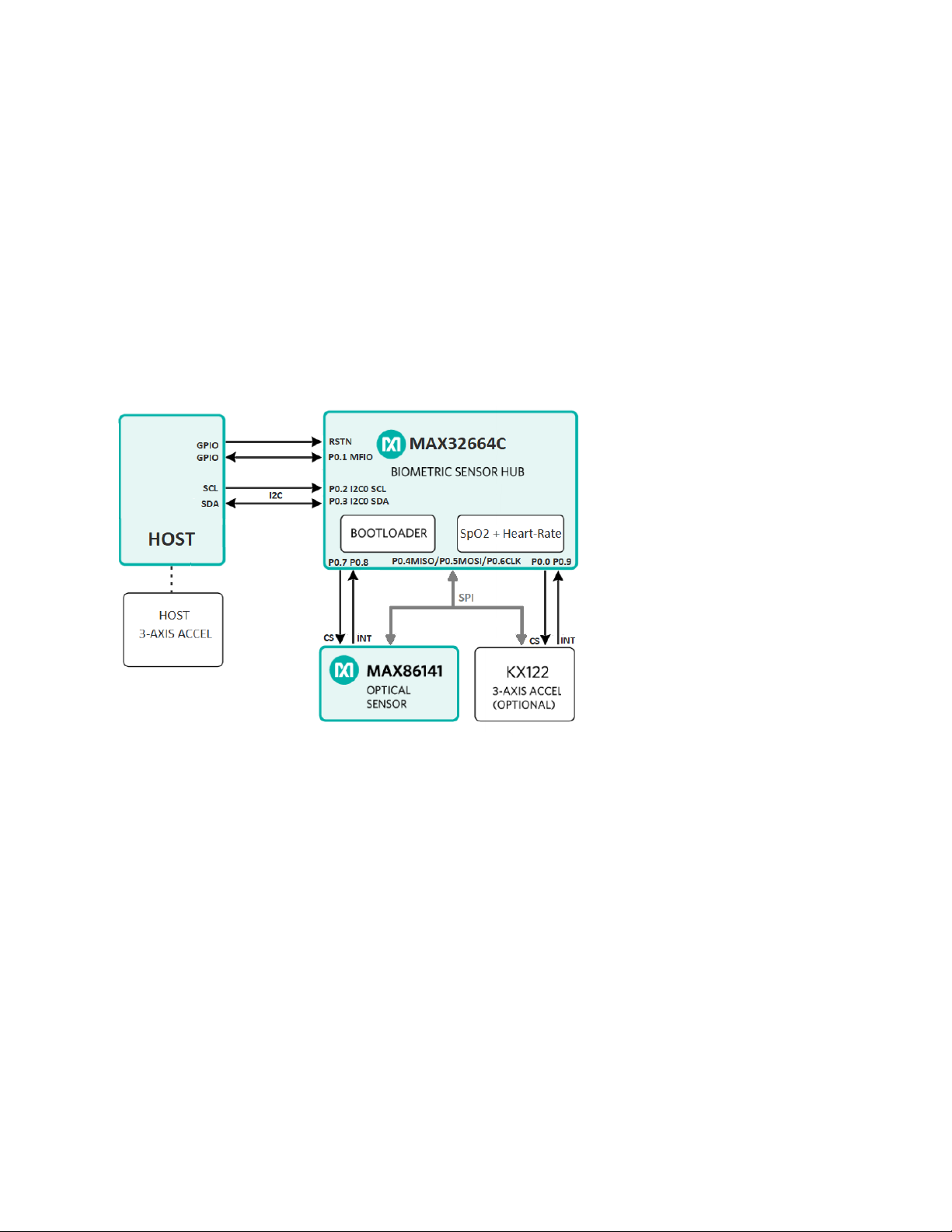
A sensor hub accelerometer can be integrated through the SPI port of the MAX32664C. In this
case, the required driver for KX122 is already included. The user only needs to follow the
reference schematics to connect the accelerometer and enable it before starting the algorithm,
as described later in this document.
Alternatively, a host-side accelerometer can be used. In this case, the host is required to use a 3-
axis accelerometer at 25Hz sampling and must periodically (e.g., once every 100ms–200ms)
provide accelerometer samples to the MAX32664C using commands shown in Table 2. Note that
this option requires strict timing synchronization between the sampled accelerometer data and
PPG samples of 40ms or less.
Table 2. Host-Side Accelerometer—Sending Data to MAX32664C
HOST COMMAND
(HEX) DESCRIPTION
MAX32664
RESPONSE
(HEX)
DESCRIPTION
AA 44 04 01 01
Enable host accelerometer.
AB 00
Success
AA 13 00 04 Read the sensor sample size for
the accelerometer. (optional) AB 00 06
Success; 6 is the
number of bytes per
samples in FIFO
The following should be executed periodically:
AA 14 00 [Sample
1 values] …
[Sample N values]
Write data to the input FIFO of
sensor hub.
Each sample is three 2-byte
integer values for X, Y, Z in milli-g.
AB 00 Success
AA 00 00 Read the sensor hub status. AB 00 00
Success; sensor hub
not busy

Maxim Integrated Page 8 of 24
2 Measuring SpO2on Wrist (WSpO2)
2.1 Initial Calibration Mode for Final Product
Due to variations in the physical design and optical shield of the final product, a calibration
procedure is required to be performed once in a controlled environment. This procedure is
important to ensure the quality of SpO2 calculation. This step is typically performed in a standard
lab with a reference SpO2device to determine three calibration coefficients: a, b, and c. The
details of the calibration procedure are described in the Guidelines for SpO2 Measurement
Using the Maxim MAX32664 Sensor Hub application note.
Once three calibrations coefficients are obtained, they need to be loaded to the MAX32664C
every time prior to starting the algorithm. But first, they are required to be converted to 32-bit
integer format using the following:
- Aint32 = round (105x a)
- Bint32 = round (105x b)
- Cint32 = round (105x c)
For example, the default measured calibration coefficients are:
- a = -16.666666
- b = 8.333333
- c = 100
They are sent to the MAX32664C in integer format after conversion:
- Aint32 = round (105x a) = 0xFFE69196
- Bint32 = round (105x b) = 0x000CB735
- Cint32 = round (105x c) = 0x00989680
The calibration coefficients may be stored in the host flash separately and loaded to the
MAX32664C after every reset.
Table 3shows the sequence of commands for calibration process. Table 4shows the format of
received samples. Typically, R values are needed for calibration process as described in the
Guidelines for SpO2 Measurement Using the Maxim MAX32664 Sensor Hub application note.

Maxim Integrated Page 9 of 24
Table 3. Host Commands—WSpO2in Calibration Mode
# HOST COMMAND (HEX) COMMAND DESCRIPTION RESPONSE
(HEX)
START ALGORITHM
Host initializes MAX32664C in calibration mode and starts algorithm using following commands:
1.1
AA 10 00 03
Set output mode to sensor + algorithm data
(streamed data will include PPG,
accelerometer, and algorithm data. R is
required for calibration).
AB 00
1.2
AA 10 01 05
Set sensor hub interrupt threshold.
AB 00
1.3
AA 44 00* 01 00
Enable analog front-end (AFE) (e.g.,
MAX86141) * with sensor hub samples.
AB 00
1.4
AA 44 04* 01 00 (if sensor hub
accelerometer is used)
AA 44 04* 01 01 (if host
accelerometer is used)
Enable accelerometer with sensor hub or
host-side accelerometer.*
AB 00
1.5
AA 50 05 02 02
Set WSpO2in Calibration mode.
AB 00
1.6
Optional: Any command to change the algorithm settings and configurations (Table 9) from default
should appear here BEFORE enabling algorithm.
1.7
AA 52 05 01
Enable WSpO2algorithm.
AB 00
READING SAMPLES
Host reads samples upon receiving MFIO interrupt by MAX32664C (repeated as needed):
2.1
AA 00 00
Read sensor hub status byte:
Bit 0: Sensor comm error
Bits 1 and 2: Reserved
Bit 3: FIFO filled to threshold (DataRdyInt)
Bit 4: Output FIFO overflow (FifoOutOvrInt)
Bit 5: Input FIFO overflow (FifoInOverInt)
Bit 6: Sensor hub busy (DevBusy)
Bit 7: Reserved
If DataRdyInt is set, proceed to next step.
AB 00 08
2.2
AA 12 00
Get the number of samples (nn) in the FIFO.
AB 00 nn
2.3
AA 12 01
Read the data stored in the FIFO; nn samples
(33 bytes each) will be included. The format of
samples is shown in Table 4.
AB 00
data_for_
nn_samples
STOP
Host ends the procedure:
3.1
AA 44 00* 00
Disable AFE (e.g., MAX86141).*
AB 00
3.2
AA 44 04* 00
Disable accelerometer.*
AB 00
3.3
AA 52 05 00
Disable WSpO2algorithm.
AB 00
*Provided indexes are examples for sensors such as the MAX86141 AFE or KX122
accelerometer.

Maxim Integrated Page 10 of 24
Table 4. Format of Received Samples—WSpO2in
Calibration/Algorithm Mode
DATA SOURCE BYTE
INDEX DATA ITEM
NUMBER OF
BYTES
(MSB FIRST)
DESCRIPTION
MAX86141
PPG Data
(18 Bytes)
0 LED1 3 N/A
3
LED2
3
N/A
6 LED3 3 N/A
9
LED4
3
Red LED counter
12 LED5 3 IR LED counter
15
LED6
3
N/A
Accelerometer
(6 Bytes)
18 accelX 2 Two's complement. LSB = 0.001g
20
accelY
2
Two's complement. LSB = 0.001g
22 accelZ 2 Two's complement. LSB = 0.001g
SpO2Algorithm
(9 Bytes)
24
R
2
10x calculated R value
26 Confidence 1 Calculated confidence in %
27
SpO2
2
10x SpO2%
29 % complete 1
Calculation progress in % (only in
one-shot mode of algorithm)
30
Low SNR
flag
1 Shows low SNR in measurement
31 Motion flag 1 Shows excessive motion
32 Status 1
Reported status of algorithm:
LED adjustment: 0
Computation: 1
Success: 2
Timeout: 3

Maxim Integrated Page 11 of 24
2.2 Raw Data Collection Mode
For hardware testing purposes, the user may choose to start the MAX32664C to collect raw PPG
samples. There are two ways to accomplish this, which are detailed as follows.
2.2.1 Raw Data Collection in Algorithm Mode
In Algorithm mode, AGC may be turned off to collect raw PPG data, as seen in the first step in
Table 5. In this case, LED currents will not be adjusted automatically; the SpO2measurement
algorithm may not converge and should be discarded. Although the algorithm is running, it will not
affect the PPG samples. If the reported PPG data is saturated, you can reduce the LED currents,
as shown in Table 5. Note that updating the MAX86141 registers should occur AFTER enabling
the algorithm and the MAX86141, or they will be overwritten during initialization.
Table 5. Host Commands—WSpO2 Raw Data with Algorithm Mode
# HOST COMMAND
(HEX) COMMAND DESCRIPTION RESPONSE
(HEX)
START ALGORITHM
Host initializes MAX32664C in Algorithm mode with AGC off and starts algorithm using following
commands:
1.1
AA 50 05 03 00
Turn off algorithm AGC.
AB 00
1.2
AA 10 00 03
Set output mode to sensor + algorithm data
(streamed data will include PPG, accelerometer,
and algorithm data. But only PPG and
accelerometer data are needed for raw data
collection and other fields can be ignored).
AB 00
1.3
AA 10 01 05
Set sensor hub interrupt threshold.
AB 00
1.4
AA 44 00* 01 00
Enable AFE (e.g., MAX86141)* with sensor hub
samples.
AB 00
1.5
AA 44 04* 01 00 (if sensor
hub accelerator is used)
AA 44 04* 01 01 (if host
accelerator is used)
Enable accelerometer with sensor hub or host-side
accelerometer.*
AB 00
1.6
Optional: Any command to change the algorithm settings and configurations (Table 9) from default
should appear here BEFORE enabling algorithm.
1.7
AA 52 05 01
Enable WSpO2algorithm.
AB 00
Wait for 100ms before sending next command. Any command to change sensor registers should
appear AFTER enabling algorithm or they will be overwritten.
By default, WSpO2algorithm sets following AFE registers:
•Sample rate: 25Hz, 1 sample averaging
•Integration time: 117μs
•ADC 1 and 2 range: 32μA
•LED 2 and 3 full range: 124mA
1.8
AA 40 00 24 [7F]
Set MAX86141 LED2 (IR) current to half of full
scale. Reduce [7F] if signal is saturated.
AB 00
1.9
AA 40 00 25 [7F]
Set MAX86141 LED3 (red) current to half of full
scale. Reduce [7F] if signal is saturated.
AB 00
1.10
AA 40 00 12 18
Set sample rate of MAX86141 to 100Hz with 1
sample averaging.
AB 00
READING
SAMPLES
Host reads samples upon receiving MFIO interrupt by MAX32664C (repeated as needed):
2.1
AA 00 00
Read sensor hub status byte:
Bit 0: Sensor comm error
Bits 1 and 2: Reserved
Bit 3: FIFO filled to threshold (DataRdyInt)
Bit 4: Output FIFO overflow (FifoOutOvrInt)
Bit 5: Input FIFO overflow (FifoInOverInt)
Bit 6: Sensor hub busy (DevBusy)
AB 00 08

Maxim Integrated Page 12 of 24
Bit 7: Reserved
If DataRdyInt is set, proceed to next step.
2.2
AA 12 00
Get the number of samples (nn) in the FIFO.
AB 00 nn
2.3
AA 12 01
Read the data stored in the FIFO; nn samples (33
bytes each) will be read. The format of samples is
shown in Table 4.
AB 00
data_for_
nn_samples
STOP
Host ends the procedure:
3.1
AA 44 00* 00
Disable AFE (e.g., MAX86141).*
AB 00
3.2
AA 44 04* 00
Disable accelerometer.*
AB 00
3.3
AA 52 05 00
Disable WSpO2algorithm.
AB 00
*Provided indexes are examples for sensors such as the MAX86141 AFE or KX122
accelerometer.

Maxim Integrated Page 13 of 24
2.2.2 Pure Raw Data Collection
The host can configure the MAX32664C to work in Raw-Only mode (no algorithm). Table 6 lists
the set of commands that are needed to work in this mode. In this case, only LED counters and
accelerometer data will be included in the received samples.
Table 6. Host Commands—WSpO2Pure Raw Data
#
HOST COMMAND
(HEX) COMMAND DESCRIPTION
RESPONSE
(HEX)
START ALGORITHM
Host initializes MAX32664C in pure raw data using following commands:
1.1
AA 10 00 01
Set output mode to sensor only.
AB 00
1.2
AA 10 01 05
Set sensor hub interrupt threshold.
AB 00
1.3
AA 44 00* 01 00
Enable AFE (e.g., MAX86141)* with sensor hub
samples.
AB 00
1.4
AA 44 04* 01 00 (if sensor
hub accelerometer is used)
AA 44 04* 01 01 (if host
accelerometer is used)
Enable accelerometer with sensor hub or host-side
accelerometer.*
AB 00
1.5
AA 40 00 12 18
Set sample rate of MAX86141 to 100Hz with 1
sample averaging.
AB 00
1.6
AA 40 00 11 3F
Set MAX86141 to integration time: 117μs and ADC
1/2 range: 32μA.
AB 00
1.7
AA 40 00 23 00
Set MAX86141 LED1 (green) current to 0.
AB 00
1.8
AA 40 00 24 [7F]
Set MAX86141 LED2 (IR) current to half of full scale.
Reduce [7F] if signal is saturated.
AB 00
1.9
AA 40 00 25 [7F]
Set MAX86141 LED3 (red) current to half of full
scale. Reduce [7F] if signal is saturated.
AB 00
1.10
AA 40 00 2A 3C
Set MAX86141 LEDs 2 and 3 current full range =
124mA.
AB 00
1.11
AA 40 00 20 23
Set MAX86141 LED sequence.
LED3 (red) -> LED2 (IR)
AB 00
1.12
AA 40 00 09 7C
Set MAX86141 FIFO interrupt threshold to 124.
AB 00
1.13
AA 40 00 0A 0E
Set MAX86141 FIFO configuration.
AB 00
1.14
AA 40 00 02 86
Set MAX86141 Interrupt configuration.
AB 00
READING SAMPLES
Host reads samples upon receiving MFIO interrupt by MAX32664C (repeated as needed):
2.1
AA 00 00
Read sensor hub status byte:
Bit 0: Sensor comm error
Bits 1 and 2: Reserved
Bit 3: FIFO filled to threshold (DataRdyInt)
Bit 4: Output FIFO overflow (FifoOutOvrInt)
Bit 5: Input FIFO overflow (FifoInOverInt)
Bit 6: Sensor hub busy (DevBusy)
Bit 7: Reserved
If DataRdyInt is set, proceed to next step.
AB 00 08
2.2
AA 12 00
Get the number of samples (nn) in the FIFO.
AB 00 nn
2.3
AA 12 01
Read the data stored in the FIFO; nn samples (24
bytes each) will be included. The format of samples
is shown in Table 7.
AB 00
data_for_
nn_samples
STOP
Host ends the procedure:
3.1
AA 44 00* 00
Disable AFE (e.g., MAX86141).*
AB 00
3.2
AA 44 04* 00
Disable accelerometer.*
AB 00
**Provided indexes are examples for sensors such as the MAX86141 AFE or KX122
accelerometer.

Maxim Integrated Page 14 of 24
Table 7. Format of Received Samples—WSpO2in Pure Raw Mode
DATA SOURCE BYTE
INDEX
DATA
ITEM
NUMBER OF
BYTES
(MSB FIRST)
DESCRIPTION
MAX86141
PPG Data
(18 Bytes)
0
LED1
3
N/A
3
LED2
3
N/A
6
LED3
3
N/A
9
LED4
3
Red LED counter
12
LED5
3
IR LED counter
15
LED6
3
N/A
Accelerometer
(6 Bytes)
18
accelX
2
Two's complement. LSB = 0.001g
20
accelY
2
Two's complement. LSB = 0.001g
22
accelZ
2
Two's complement. LSB = 0.001g

Maxim Integrated Page 15 of 24
2.3 Algorithm Mode
In Algorithm mode, WSpO2algorithm is enabled to calculate R value, SpO2and confidence level.
AGC is enabled in this mode and algorithm runs in one-shot mode by default. In one-shot mode,
the progress is reported as %. You may change it to continuous mode as shown below. If signal
quality is low, a LowSNR flag will be set. Excessive motion is also reported with a flag. The
sequence of commands is shown in Table 8.
Table 8. Host Commands—WSpO2Algorithm Mode
# HOST COMMAND (HEX) COMMAND DESCRIPTION
RESPONSE
(HEX)
START ALGORITHM
Host initializes the MAX32664C in Algorithm mode using the following commands:
1.1
AA 50 05 00
[FFE69196000CB7350098
9680]*
This step is ONLY needed if non-default calibration
coefficients are used to write SpO2calibration
coefficients as derived according to [1]. Provided
coefficients are for example only*.
AB 00
1.2
AA 10 00 03
Set output mode to sensor + algorithm data
(streamed data will include PPG, accelerometer,
and algorithm data. But only PPG and
accelerometer data are needed for raw data
collection and other fields can be ignored.
AB 00
1.3
AA 10 01 05
Set sensor hub interrupt threshold.
AB 00
1.4
AA 44 00** 01 00
Enable AFE (e.g., MAX86141)** with sensor hub
samples.
AB 00
1.5
AA 44 04** 01 00 (if sensor
hub accelerometer is used)
AA 44 04** 01 01 (if host
accelerometer is used)
Enable accelerometer with sensor hub or host-side
accelerometer.**
AB 00
1.6
AA 50 05 02 [00]
Set algorithm run mode to continuous (default is
one-shot [01]). See Table 9.
1.7
Optional: Any command to change the algorithm settings and configurations (Table 9) from default
should appear here BEFORE enabling algorithm.
1.8
AA 52 05 01
Enable WSpO2algorithm.
AB 00
READING SAMPLES
Host reads samples upon receiving MFIO interrupt by MAX32664C (repeated as needed):
2.1
AA 00 00
Read sensor hub status byte:
Bit 0: Sensor comm error
Bits 1 and 2: Reserved
Bit 3: FIFO filled to threshold (DataRdyInt)
Bit 4: Output FIFO overflow (FifoOutOvrInt)
Bit 5: Input FIFO overflow (FifoInOverInt)
Bit 6: Sensor hub busy (DevBusy)
Bit 7: Reserved
If DataRdyInt is set, proceed to next step.
AB 00 08
2.2
AA 12 00
Get the number of samples (nn) in the FIFO.
AB 00 nn
2.3
AA 12 01
Read the data stored in the FIFO; nn samples (33
bytes each) will be read. The format of samples is
shown in Table 4.
AB 00
data_for_
nn_samples
STOP
Host ends the procedure:
3.1
AA 44 00* 00
Disable AFE (e.g., MAX86141).*
AB 00
3.2
AA 44 04* 00
Disable accelerometer.*
AB 00
3.3
AA 52 05 00
Disable WSpO2 algorithm.
AB 00
*Provided 12-byte calibration data is an example. Actual data should be derived as described in
[1].
**Provided indexes are examples for sensors such as the MAX86141 AFE or KX122
accelerometer.

Maxim Integrated Page 16 of 24
2.3.1 Algorithm Settings and Configurations
The settings shown in Table 9are available for the WSpO2algorithm. To update the Algorithm
settings, make sure to send the appropriate commands BEFORE enabling the algorithm, as
shown in Table 8.
Table 9. Configurations and Settings—WSpO2
FAMILY
BYTE
ALGORITHM
INDEX
CONFIGURATION
INDEX DESCRIPTION
DEFAULT
VALUE
(MSB FIRST)
0x50 for
write
0x51 for
read
0x05
0x00
WSpO
2
Calibration Coefficients x
100,000 (12 bytes comprised of three
32-bit signed values)
0xFFE69196
000CB735
00989680
0x01
Sampling rate (Hz):
0x00: 100Hz:
0x01: 25Hz
0x01
0x02
Algorithm run mode:
0x00: continuous
0x01: one-shot
0x02: calibration (to collect data for
calibration as in [1])
0x01
0x03
AGC enable:
0x00: Disable
0x01: Enable
0x01
0x04
Motion detection enable:
0x00: Disable
0x01: Enable
0x01
0x05
Motion detection period in seconds
(16-bit unsigned)
0x0002
0x06
Accelerometer motion detection
threshold in milli-g times 100,000
(32-bit signed)
0x01C9C380
0x07
AGC timeout in seconds
(8-bit unsigned)
0x1E
0x08 WSpO2algorithm timeout in seconds 0x78
0x09
Configure the source of the PPG signal
for the photo detector (PD)
0x01: PD1 only
0x02: PD2 only
0x02

Maxim Integrated Page 17 of 24
3 Measuring Heart-Rate on Wrist (WHRM)
3.1 Setup
A typical heart-rate sensing design has two PDs that are located at the same distance from green
LED. In this case, PPG signal from both PDs can be used for WHRM calculation.
For other type of PD setups, set the PD configuration from the host accordingly using the
commands provided in Table 15 prior to enabling the algorithm.
3.2 Raw Data Collection Mode
For hardware testing purposes, the user may choose to start the MAX32664C to collect raw PPG
samples. There are two ways to accomplish this, which are detailed as follows.
3.2.1 Raw Data Collection in Algorithm Mode
In Algorithm mode, automatic exposure control (AEC) and skin contact detection (SCD) may be
turned off to collect raw PPG data (steps 1.1 and 1.2 in Table 10). In this case, LED currents will
not be adjusted automatically; the heart-rate measurement algorithm may not converge and
should be discarded. Although the algorithm is running, it will not affect the PPG samples. If the
reported PPG data is saturated, you can reduce the LED currents. Note that updating the
MAX86141 registers should occur AFTER enabling the algorithm and the MAX86141, or they will
be overwritten during initialization.

Maxim Integrated Page 18 of 24
Table 10. Host Commands—WHRM Raw Data with Algorithm Mode
# HOST COMMAND
(HEX) COMMAND DESCRIPTION RESPONSE
(HEX)
START ALGORITHM
Host initializes the MAX32664C in Algorithm mode with AEC and SCD off and starts algorithm using
the following commands:
1.1
AA 50 02 0B 00
Turn off algorithm AEC.
AB 00
1.2
AA 50 02 0C 00
Turn off algorithm SCD.
AB 00
1.3
AA 10 00 03
Set output mode to sensor + algorithm data.
AB 00
1.4
AA 10 01 05
Set sensor hub interrupt threshold.
1.5
AA 44 00* 01 00
Enable AFE (e.g., MAX86141)* with sensor
hub samples.
AB 00
1.6
AA 44 04* 01 00 (if sensor
hub accelerometer is used)
AA 44 04* 01 01 (if host
accelerometer is used)
Enable accelerometer with sensor hub or
host-side accelerometer.*
AB 00
1.7
Optional: Any command to change the algorithm settings and configurations (Table 15) from
default should appear here BEFORE enabling algorithm.
1.8
AA 52 02 01
Enable WHRM algorithm.
AB 00
Wait for 100ms before sending next command. Any command to change sensor registers should
appear AFTER enabling algorithm or they will be overwritten.
By default, WHRM sets the following AFE registers:
•Sample rate is 100Hz, 4 sample averaging
•Integration time: 117μs
•ADC 1 and 2 range: 32μA
•LED 1 full range: 124mA
1.9
AA 40 00 23 [7F]
Set the MAX86141 LED1 current to half of full
scale. Reduce [7F] if signal is saturated.
AB 00
1.10
AA 40 00 12 18
Set sample rate of the MAX86141 to 100Hz
with 1 sample averaging.
AB 00
READING SAMPLES
Host reads samples upon receiving MFIO interrupt by the MAX32664C (repeated as needed):
2.1
AA 00 00
Read sensor hub status byte:
Bit 0: Sensor comm error
Bits 1 and 2: Reserved
Bit 3: FIFO filled to threshold (DataRdyInt)
Bit 4: Output FIFO overflow (FifoOutOvrInt)
Bit 5: Input FIFO overflow (FifoInOverInt)
Bit 6: Sensor hub busy (DevBusy)
Bit 7: Reserved
If DataRdyInt is set, proceed to next step.
AB 00 08
2.2
AA 12 00
Get the number of samples (nn) in the FIFO.
AB 00 nn
2.3
AA 12 01
Read the data stored in the FIFO; nn samples
(30 bytes each) will be read. The format of
samples is shown in Table 11.
AB 00
data_for_
nn_samples
STOP
Host ends the procedure:
3.1
AA 44 00* 00
Disable AFE (e.g., MAX86141).*
AB 00
3.2
AA 44 04* 00
Disable accelerometer.*
AB 00
3.3
AA 52 02 00
Disable WHRM algorithm.
AB 00
*Provided indexes are examples for sensors such as the MAX86141 AFE or KX122
accelerometer.

Maxim Integrated Page 19 of 24
Table 11. Format of Received Samples—WHRM in Algorithm Mode
DATA SOURCE BYTE
INDEX
DATA
ITEM
NUMBER OF
BYTES (MSB
FIRST)
DESCRIPTION
MAX86141
(18 Bytes)
0
LED1
3
Green 1 counter
3
LED2
3
N/A
6
LED3
3
N/A
9
LED4
3
Green 2 counter
12
LED5
3
N/A
15
LED6
3
N/A
Accelerometer
(6 Bytes)
18
accelX
2
Two's complement. LSB = 0.001g
20
accelY
2
Two's complement. LSB = 0.001g
22
accelZ
2
Two's complement. LSB = 0.001g
WHRM
Algorithm
(6 Bytes)
24
HR
2
10x heart rate
26
Confidence
1
Calculated confidence in %
27
RR
2
10x RR - inter-beat interval in ms
29 Activity
class 1
Activity class:
Rest: 0
Other: 1
Walk: 2
Run: 3
Bike: 4
Rhythmic: 5

Maxim Integrated Page 20 of 24
3.2.2 Pure Raw Data Collection
The host can configure the MAX32664C to work in Raw-Only mode (no algorithm). Table 12 lists
the set of commands that are needed to work in this mode. In this case, only the LED counters
and accelerometer data will be included in the received samples.
Table 12. Host Commands—WHRM Pure Raw Data
#
HOST COMMAND
(HEX)
COMMAND DESCRIPTION
RESPONSE
(HEX)
START ALGORITHM
Host initializes the MAX32664C in pure raw data using the following commands:
1.1
AA 10 00 01
Set output mode to sensor only.
AB 00
1.2
AA 10 01 05
Set sensor hub interrupt threshold.
AB 00
1.3
AA 44 00* 01 00
Enable AFE (e.g., MAX86141)* with sensor hub
samples.
AB 00
1.4
AA 44 04* 01 00
Enable accelerometer with sensor hub.*
AB 00
1.5
AA 40 00 12 18
Set sample rate of MAX86141 to 100Hz with 1
sample averaging.
AB 00
1.6
AA 40 00 11 3F
Set MAX86141 to integration time: 117μs and ADC
1/2 range: 32μA.
AB 00
1.7
AA 40 00 23 [7F]
Set MAX86141 LED1 current to half of full scale.
Reduce [7F] if signal is saturated.
AB 00
1.8
AA 40 00 2A 03
Set MAX86141 LED1 current full range = 124mA.
AB 00
1.9
AA 40 00 20 21
Set MAX86141 LED sequence
LED1 (green) -> LED2 (IR)
AB 00
1.10
AA 40 00 09 7C
Set MAX86141 FIFO interrupt threshold to 124.
AB 00
1.11
AA 40 00 0A 0E
Set MAX86141 FIFO configuration.
AB 00
1.12
AA 40 00 02 86
Set MAX86141 interrupt configuration.
AB 00
READING SAMPLES
Host reads samples upon receiving MFIO interrupt by the MAX32664C (repeated as needed):
2.1
AA 00 00
Read sensor hub status byte:
Bit 0: Sensor comm error
Bits 1 and 2: Reserved
Bit 3: FIFO filled to threshold (DataRdyInt)
Bit 4: Output FIFO overflow (FifoOutOvrInt)
Bit 5: Input FIFO overflow (FifoInOverInt)
Bit 6: Sensor hub busy (DevBusy)
Bit 7: Reserved
If DataRdyInt is set, proceed to next step.
2.2
AA 12 00
Get the number of samples (nn) in the FIFO
2.3
AA 12 01
Read the data stored in the FIFO; nn samples (24
bytes each) will be read. The format of samples is
shown in Table 13.
STOP
Host ends the procedure:
3.1
AA 44 00 * 00
Disable AFE (e.g., MAX86141).*
AB 00
3.2
AA 44 04* 00
Disable accelerometer.
AB 00
*Provided indexes are examples for sensors such as the MAX86141 AFE or KX122
accelerometer.
Table of contents
Other Maxim Integrated Medical Equipment manuals