Maxim Integrated MAXREFDES101 User manual

Maxim Integrated Page 1 of 39
MAXREFDES101#: Health Sensor Platform 2.0
User Guide
UG6780; Rev 2; 8/19
Abstract
This user guide provides information about preparing and running the MAXREFDES101# Health
Sensor Platform. This platform uses several biosensors, power-management ICs (PMIC), and
microcontrollers from Maxim Integrated®in a wrist worn design that allows the capture of
biosignals important to healthcare. The platform also contains algorithms for calculating heart
health based on the biosensor measurements.

Maxim Integrated Page 2 of 39
Table of Contents
Detailed Hardware Description................................................................................................... 5
Required Equipment .................................................................................................................. 6
System Diagram ........................................................................................................................ 7
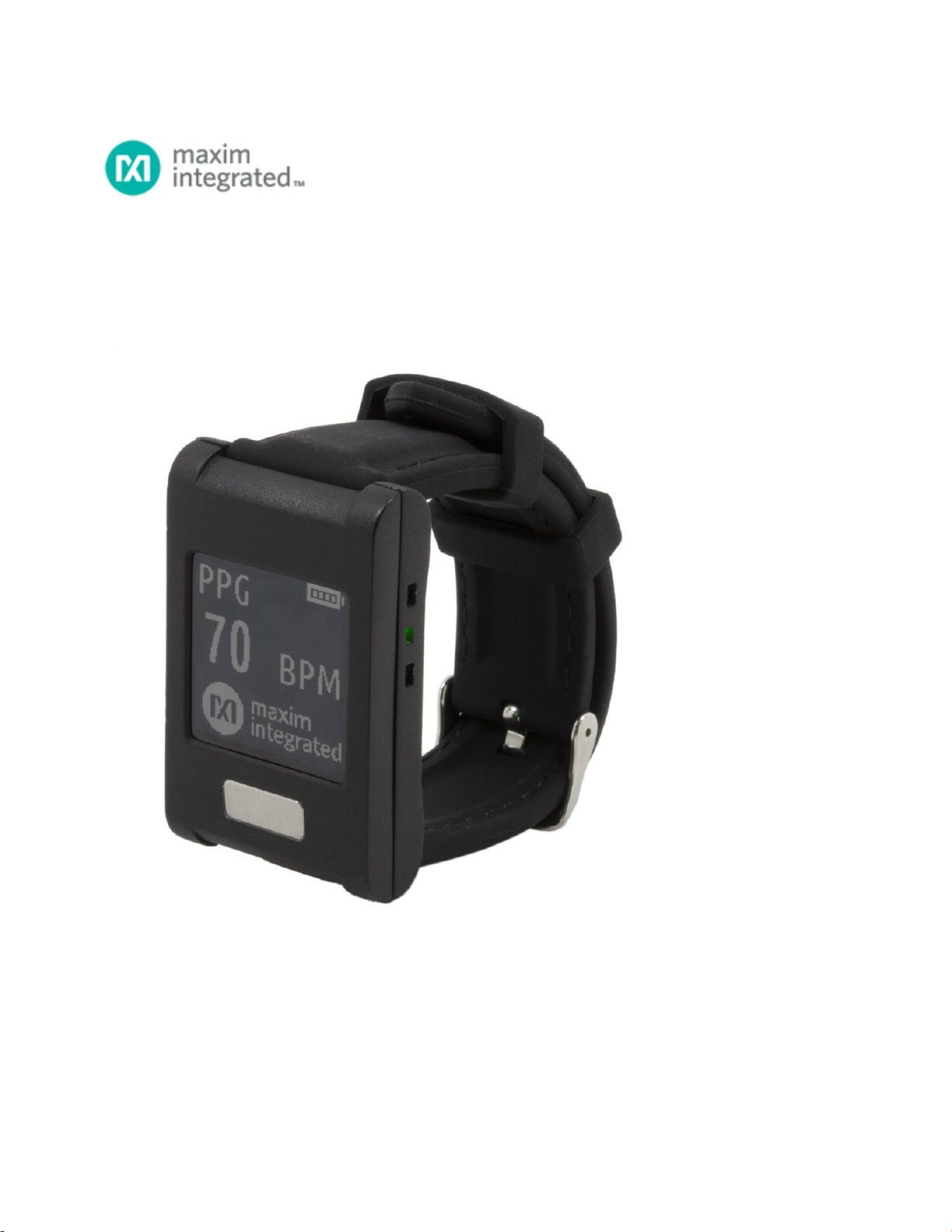
Operating the Watch.................................................................................................................. 8
Power On/Off.......................................................................................................................... 8
Display Modes........................................................................................................................ 9
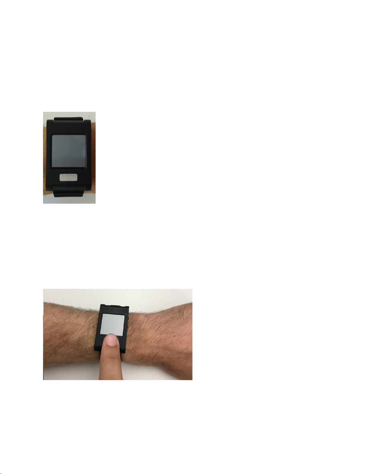
How to Wear the Device........................................................................................................10
PPG Measurement ............................................................................................................10
ECG Measurement............................................................................................................10
Body Temperature Measurement.......................................................................................10
Installing the PC GUI.................................................................................................................11
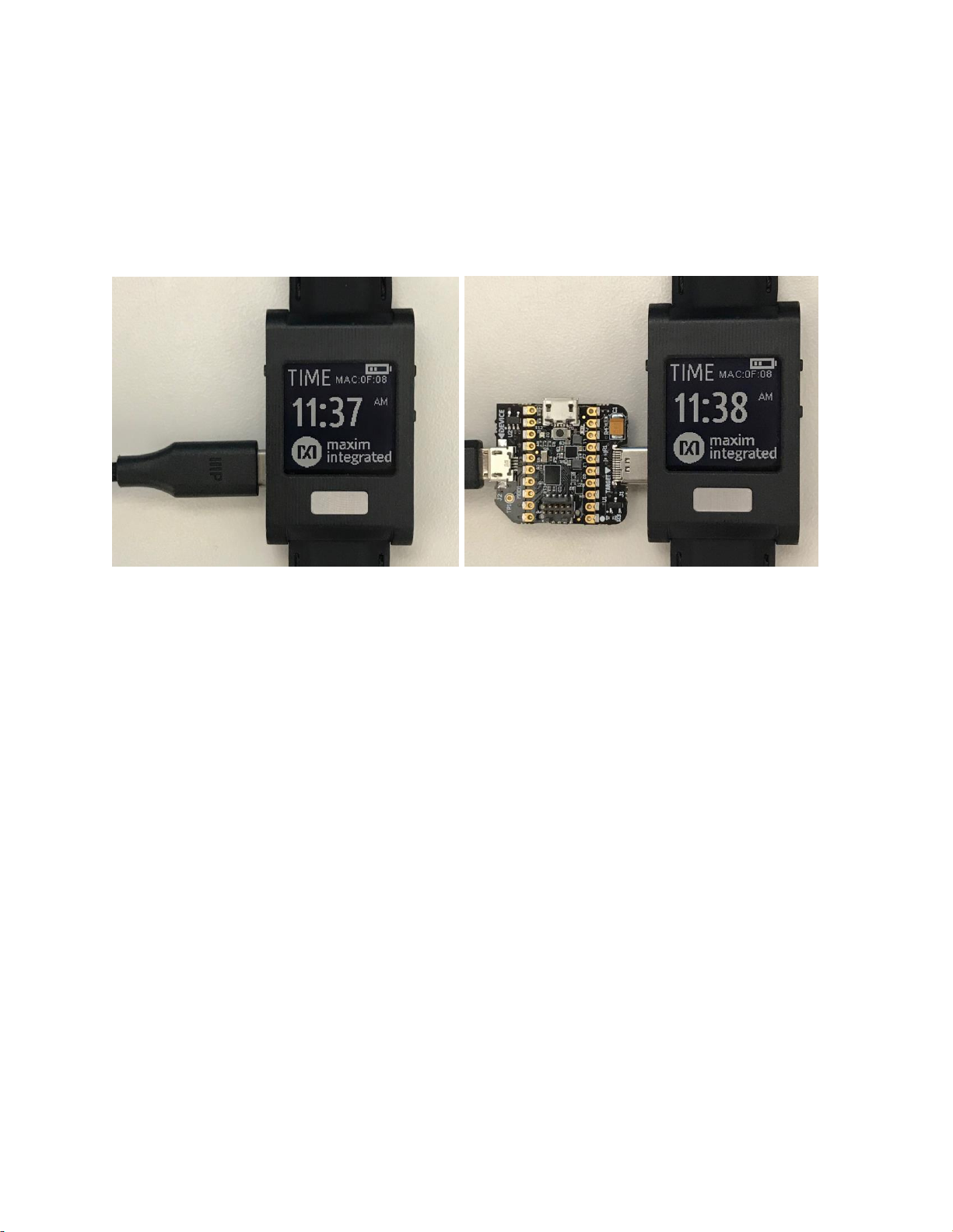
Upgrading the Firmware on MAXREFDES101#........................................................................12
Updating the Sensor Hub Algorithm ......................................................................................13
Using the PC GUI .....................................................................................................................16
USB Connection....................................................................................................................16
BLE Connection ....................................................................................................................19
Starting the ECG Measurement.............................................................................................20
Starting the Temperature Measurement................................................................................22
Starting the PPG Measurement.............................................................................................23
Installing the Android App.........................................................................................................25
Using the Android App..............................................................................................................26
BLE Connection for Android..................................................................................................26
Starting the ECG Measurement for Android ..........................................................................27
Starting the PPG Measurement for Android...........................................................................29
Starting the Temperature Measurement for Android..............................................................30
Installing the Windows 7 Driver.................................................................................................32
Flash Logging ...........................................................................................................................34
Downloading the Log File......................................................................................................34
Data Format..............................................................................................................................36
Revision History........................................................................................................................39

Maxim Integrated Page 3 of 39
List of Figures
Figure 1. MAXREFDES101# wearable form factor in detail........................................................ 5
Figure 2. MAXREFDES101# exploded view. ............................................................................. 5
Figure 3. MAXREFDES101# system diagram............................................................................ 7
Figure 4. USB Type-C cable (left) and Pico adapter board (right)............................................... 8
Figure 5. Watch display modes.................................................................................................. 9
Figure 6. PPG measurement.....................................................................................................10
Figure 7. ECG measurement. ...................................................................................................10
Figure 8. Install the .msi file.......................................................................................................11
Figure 9. Pico adapter connected to the PC..............................................................................12
Figure 10. DAPLINK drive on the PC........................................................................................12
Figure 11. Maxim DeviceStudio scan options............................................................................13
Figure 12. Maxim DeviceStudio connected devices. .................................................................14
Figure 13. Upload embedded heart-rate algorithm to the MAX32664........................................15
Figure 14. USB connection to PC using a USB Type-C cable (left) and Pico adapter board (right). 16
Figure 15. Scan for devices.......................................................................................................17
Figure 16. Successful connection over USB. ............................................................................18
Figure 17. BLE device selection................................................................................................19
Figure 18. Successful connection over BLE..............................................................................19
Figure 19. Start the ECG measurement....................................................................................20
Figure 20. ECG measurement sample......................................................................................21
Figure 21. Start the temperature measurement.........................................................................22
Figure 22. Start the PPG measurement. ...................................................................................23
Figure 23. PPG measurement sample......................................................................................24
Figure 24. Install the Android app..............................................................................................25
Figure 25. Available Devices list. ..............................................................................................26
Figure 26. Mode selection view.................................................................................................26
Figure 27. Start the ECG measurement for the Android app.....................................................27
Figure 28. Android app ECG measurement sample..................................................................28
Figure 29. Android app PPG measurement sample..................................................................29

Maxim Integrated Page 4 of 39
Figure 30. Start the temperature measurement for the Android app..........................................30
Figure 31. Android app temperature measurement sample.......................................................31
Figure 32. CDC DEVICE in Device Manager. ...........................................................................32
Figure 33. Locate and install the driver manually. .....................................................................32
Figure 34. Browse to extracted release package.......................................................................33
Figure 35. Choose Install this driver software anyway...............................................................33
Figure 36. mbed Serial Port in Device Manager........................................................................33
Figure 37. MSD connection to PC using USB Type-C cable (left) and Pico adapter board (right).34
Figure 38. Flash Log Parser......................................................................................................35
Figure 39. Log file PPG_.csv for PPG measurement.................................................................36
Figure 40. Log file ECG_.csv for ECG measurement................................................................37
Figure 41. Log file Temp_.csv for body temperature measurement...........................................38
List of Tables
Table 1. PPG Raw Data Table Column Definitions (PPG_*.csv)...............................................36
Table 2. ECG Raw Data Table Column Definitions (ECG_*.csv)...............................................37
Table 3. Temperature Raw Data Table Column Definitions (TEMP_*.csv)................................38

Maxim Integrated Page 5 of 39
Detailed Hardware Description
Figure 1. MAXREFDES101# wearable form factor in detail.
Figure 2. MAXREFDES101# exploded view.

Maxim Integrated Page 6 of 39
Required Equipment
The MAXREFDES101# platform includes the following components:
•Micro board that includes:
oMAX32630 microcontroller
oMAX20303 power-management IC (PMIC)
oDual mode Bluetooth®
oSix-axis accelerometer and gyroscope
•Sensor board that includes:
oMAX86141 analog front end and optical heart-rate sensor with one green LED
and two photodiodes
oMAX30001 ECG sensor
oMAX30205 human body temperature sensor
oMAX32664 microcontroller with embedded heart-rate algorithm
oThree-axis accelerometer
•MAXDAP-TYPE-C Pico adapter board to be used during a firmware upgrade for the micro
board
•Watch enclosure
•Battery
•1 USB Micro-B cable for firmware upgrade of the micro board
•1 USB Type-C™cablefor PC communication with the micro board orcharging of the watch
Additional requirements:
•PC or Android®device (e.g., tablet) with Bluetooth connection for data streaming and
logging
Note: PC Bluetooth connection is only supported on Windows®10. A USB connection is required
for Windows 7.
Android is a registered trademark of Google Inc.
The Bluetooth word mark and logos are registered trademarks owned by Bluetooth SIG, Inc. and
any use of such marks by Maxim is under license.
USB Type-C is a trademark of Universal Serial Bus Implementers Forum, Inc.
Windows is a registered trademark and registered service mark of Microsoft Corporation.

Maxim Integrated Page 7 of 39
System Diagram
Figure 3. MAXREFDES101# system diagram.

Maxim Integrated Page 8 of 39
Operating the Watch
Power On/Off
The MAXREDES101# can be powered on by pressing and holding button 1 for at least one
second. When the device is on, the display shows the time mode by default.
Alternatively, the device powers on when connected to a PC using a USB Type-C cable or when
connected to a Pico adapter board.
Figure 4. USB Type-C cable (left) and Pico adapter board (right).
The MAXDAP-TYPE-C Pico adapter board has two USB Micro-B connectors. The top connector
next to the push button is used for updating the firmware of the micro board. The left connector
next to the “DEVICE” label is used for the serial connection between the MAXREFDES101# and
the PC. Both connectors provide power to the MAXREFDES101#.
To power off, press and hold button 1 for at least three seconds. When LED indicator 1 turns red,
release button 1, and the device powers off.
Note: If thedevice fails to power off or becomes unresponsive, press and hold button 1 for at least
twelve seconds to perform a hard reset.

Maxim Integrated Page 9 of 39
Display Modes
The display can be toggled between time mode, PPG mode, temperature mode, and info mode.
To cycle between modes, press and release button 2 or button 3.
Figure 5. Watch display modes.
Note: There is no display in ECG mode because the noise from the display interferes with the
measurement. To take an ECG measurement, use the PC or Android application.

Maxim Integrated Page 10 of 39
How to Wear the Device
Position the watch approximately one finger width up the arm from the wrist bone. If possible,
wear the watch on the non-dominant hand, as this improves the quality of the data. The watch
should fit tightly but comfortably around the wrist.
PPG Measurement
To take a PPG measurement, wear the watch on the wrist and make sure the skin has direct
contact with the LED/photodiodes at the center of the back of the watch.
Figure 6. PPG measurement.
ECG Measurement
To take an ECG measurement, wear the watch on the wrist and make sure the skin has direct
contact with electrodes 2 and 3. Then place a finger from the opposite hand on electrode 1. For
example, if the watch is worn on the left wrist, use a finger from the right hand.
Note: For best results on Windows 7, flash logging is recommended to avoid noise over the
USB cable.
Figure 7. ECG measurement.
Body Temperature Measurement
To take a body temperature measurement, wear the watch on the wrist and make sure the skin
has direct contact with electrode 2.

Maxim Integrated Page 11 of 39
Installing the PC GUI
1. Download and extract the Eval Package for either Windows 10 or Windows 7 from the
Software section on the MAXREFDES101# Design Resources tab.
Note: The software package includes the latest firmware, algorithm, and the
corresponding Windows or Android application. All three must be updated to ensure
compatibility.
2. Double click on the .msi file. Check the box for “I accept the terms in the License
Agreement”, click on “Install,” and then click on “Finish.”
Figure 8. Install the .msi file.

Maxim Integrated Page 12 of 39
Upgrading the Firmware on MAXREFDES101#
The micro board might be shipped without the latest firmware. Maxim recommends that you
update the firmware whenever new firmware becomes available. Firmware upgrades can be
performed using the provided Pico adapter board by performing the following steps:
1. Download and extract the Eval Package from the Software section on the
MAXREFDES101# Design Resources tab.
Note: The software package includes the latest firmware, algorithm, and the
corresponding Windows or Android application. All three must be updated to ensure
compatibility.
2. Insert the Pico adapter board into the USB Type-C connector of the watch. This
establishes a connection with the micro board inside the watch assembly.
3. Connect the Pico adapter board to the PC using two USB Micro-B cables.
Figure 9. Pico adapter connected to the PC.
4. Wait for the Windows drivers to install. After the drivers have installed, the PC recognizes
the device, which shows up as a drive named DAPLINK on the PC.
Figure 10. DAPLINK drive on the PC.
5. To flash the program, use the Drag and Drop feature (e.g., drag and drop the binary file
into the DAPLINK drive on your PC).

Maxim Integrated Page 13 of 39
6. After flashing the micro board with the new firmware, the board does not automatically
reset. To restart the watch after flashing, press and release the button on the Pico adapter
board. The button is located below the top USB Micro-B connector.
Updating the Sensor Hub Algorithm
After the firmware binary is updated, the Biometric Sensor Hub algorithm can be updated with the
PC GUI by performing the following steps:
1. Download and extract the Eval Package from the Software section on the
MAXREFDES101# Design Resources tab.
Note: The software package includes the latest firmware, algorithm, and the
corresponding Windows or Android application. All three must be updated to ensure
compatibility.
2. Open the Maxim®DeviceStudio Windows application.
3. Select the “Serial over USB” Scan Option. Click “Scan.”
Figure 11. Maxim DeviceStudio scan options.
Maxim is a registered trademark of Maxim Integrated Products, Inc.

Maxim Integrated Page 14 of 39
4. Verify that Connected Devices lists ECG, Temp, and PPG.
Figure 12. Maxim DeviceStudio connected devices.
5. Go to Device Tab > Update SmartSensor_MAX32660 Software > Update Firmware and
select the *.msbl file from the extracted Eval Package.
6. The embedded heart rate algorithm is uploaded to the MAX32664 microcontroller on the
sensor board.

Maxim Integrated Page 15 of 39
Figure 13. Upload embedded heart-rate algorithm to the MAX32664.

Maxim Integrated Page 16 of 39
Using the PC GUI
The Windows 10 PC GUI currently supports connection to the MAXREFDES101# through USB
or Bluetooth Low Energy (BLE). The Windows 7 PC GUI only supports connection to the
MAXREFDES101# through USB.
USB Connection
1. Connect the watch to the PC with a USB Type-C cable (or with the Pico adapter board
with a USB Micro-B cable).
Figure 14. USB connection to PC using a USB Type-C cable (left) and Pico adapter
board (right).

Maxim Integrated Page 17 of 39
2. Under Scan Mode, select “Serial over USB.” Click “Scan.”
Figure 15. Scan for devices.

Maxim Integrated Page 18 of 39
3. Verify that Connected Devices lists ECG, TEMP, and PPG.
Figure 16. Successful connection over USB.

Maxim Integrated Page 19 of 39
BLE Connection
1. Under Scan Mode, select “Windows BLE.” Click “Scan.”
2. Select the device with the MAC address that matches the MAC address listed on the watch
info screen. Click “Connect.”
Figure 17. BLE device selection.
3. Verify that Connected Devices lists ECG, TEMP, and PPG.
Figure 18. Successful connection over BLE.

Maxim Integrated Page 20 of 39
Starting the ECG Measurement
1. Select “ECG” under Connected Devices and click on “Launch Tool.”
2. Check the box for “Log to File” to save the data to a file.
3. Check the box for “Log to Flash” to save the data to the on-board flash. Data is not
streamed to the GUI while Flash Logging is enabled.
4. Select the desired filters.
5. Adjust the ECG parameters. The default parameters can be used for the first time. Refer
to the MAX30001 data sheet for a detailed explanation of the parameters.
6. Click on “Start Monitoring.”
Note: There is no display in ECG mode because the noise from the display interferes with the
measurement.
Figure 19. Start the ECG measurement.
Table of contents
Other Maxim Integrated Medical Equipment manuals
Popular Medical Equipment manuals by other brands

AED
AED HeartPlus NT-180 User Manual & Warranty Registration

CME Medical
CME Medical BodyGuard 595 Operation manual

orfit
orfit AIO SOLUTION AC-LS-L Instructions for use

Sakamoto Model
Sakamoto Model M178 user manual

Rigel Medical
Rigel Medical Rigel BP-SIM instruction manual

Brainlab
Brainlab VECTORVISION Series Technical user guide