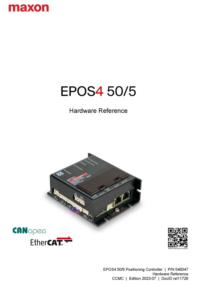
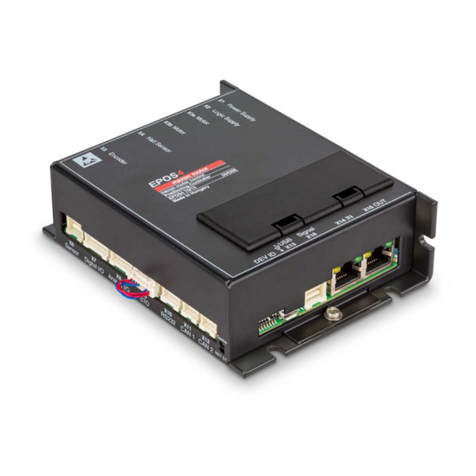
Maxon EPOS4 Use and care manual

Table of Contents
EPOS4 Communication Guide
A-2 CCMC | 2019-11 | rel8759
1 ABOUT THIS DOCUMENT 3
2 USB & RS232 COMMUNICATION 7
2.1 EPOS4 USB & RS232 Command Reference . . . . . . . . . . . . . . . . . . . . . . . . . . . . 7
2.2 Data Link Layer. . . . . . . . . . . . . . . . . . . . . . . . . . . . . . . . . . . . . . . . . . . . . . . . . . 12
2.3 Physical Layer. . . . . . . . . . . . . . . . . . . . . . . . . . . . . . . . . . . . . . . . . . . . . . . . . . . 20
3 CAN COMMUNICATION 21
3.1 General Information . . . . . . . . . . . . . . . . . . . . . . . . . . . . . . . . . . . . . . . . . . . . . . 21
3.2 CANopen Basics. . . . . . . . . . . . . . . . . . . . . . . . . . . . . . . . . . . . . . . . . . . . . . . . . 23
3.3 CANopen Application Layer . . . . . . . . . . . . . . . . . . . . . . . . . . . . . . . . . . . . . . . . 25
3.4 Identifier Allocation Scheme . . . . . . . . . . . . . . . . . . . . . . . . . . . . . . . . . . . . . . . . 34
3.5 Layer Setting Services (LSS) . . . . . . . . . . . . . . . . . . . . . . . . . . . . . . . . . . . . . . . 35
4 ETHERCAT COMMUNICATION 41
4.1 Communication Specifications . . . . . . . . . . . . . . . . . . . . . . . . . . . . . . . . . . . . . . 42
4.2 EtherCAT State Machine (ESM) . . . . . . . . . . . . . . . . . . . . . . . . . . . . . . . . . . . . . 42
4.3 Integration of ESI Files . . . . . . . . . . . . . . . . . . . . . . . . . . . . . . . . . . . . . . . . . . . . 44
4.4 Error Code Definition. . . . . . . . . . . . . . . . . . . . . . . . . . . . . . . . . . . . . . . . . . . . . . 44
5 GATEWAY COMMUNICATION (USB OR RS232 TO CAN) 45
6 COMMUNICATION ERROR CODE DEFINITION 47
TABLE OF CONTENTS
READ THIS FIRST
These instructions are intended for qualified technical personnel. Prior commencing with any activities…
• you must carefully read and understand this manual and
• you must follow the instructions given therein.
EPOS4 positioning controllers are considered as partly completed machinery according to EU Directive 2006/42/EC, Article 2,
Clause (g) and are intended to be incorporated into or assembled with other machinery or other partly completed
machinery or equipment.
Therefore, you must not put the device into service,…
• unless you have made completely sure that the other machinery fully complies with the EU directive’s requirements!
• unless the other machinery fulfills all relevant health and safety aspects!
• unless all respective interfaces have been established and fulfill the herein stated requirements!
About this Document
EPOS4 Communication Guide
CCMC | 2019-11 | rel8759 1-3
1 ABOUT THIS DOCUMENT
The present document provides you with information on the EPOS4 communication interfaces.
Find the latest edition of the present document as well as additional documentation and software for EPOS4
positioning controllers also on the Internet: http://epos.maxongroup.com.
1.1 Intended Purpose
The purpose of the present document is to familiarize you with the described equipment and the tasks on
safe and adequate installation and/or commissioning. Follow the described instructions …
• to avoid dangerous situations,
• to keep installation and/or commissioning time at a minimum,
• to increase reliability and service life of the described equipment.
The present document is part of a documentation set and contains performance data and specifications,
information on fulfilled standards, details on connections and pin assignment, and wiring examples. The
below overview shows the documentation hierarchy and the interrelationship of its individual parts:
Figure 1-1 Documentation structure

About this Document
EPOS4 Communication Guide
1-4 CCMC | 2019-11 | rel8759
1.2 Target Audience
The present document is intended for trained and skilled personnel. It conveys information on how to under-
stand and fulfill the respective work and duties.
The present document is a reference book. It does require particular knowledge and expertise specific to
the equipment described.
1.3 How to use
Take note of the following notations and codes which will be used throughout the document.
Table 1-1 Notations used in this document
1.3.1 Trademarks and Brand Names
For easier legibility, registered brand names are listed below and will not be further tagged with their respec-
tive trademark. It must be understood that the brands (the below list is not necessarily concluding) are pro-
tected by copyright and/or other intellectual property rights even if their legal trademarks are omitted in the
later course of this document.
Table 1-2 Brand names and trademark owners
Notation Explanation
EPOS4 stands for “EPOS4 Positioning Controller”
«Abcd» indicates a title or a name (such as of document, product, mode, etc.)
(n) refers to an item (such as part numbers, list items, etc.)
denotes “see”, “see also”, “take note of” or “go to”
Brand Name Trademark Owner
Adobe® Reader® © Adobe Systems Incorporated, USA-San Jose, CA
CANopen®
CiA® © CiA CAN in Automation e.V, DE-Nuremberg
EtherCAT® © EtherCAT Technology Group, DE-Nuremberg, licensed by Beckhoff Automation
GmbH, DE-Verl

About this Document
EPOS4 Communication Guide
CCMC | 2019-11 | rel8759 1-5
1.4 Sources for additional Information
For further details and additional information, please refer to below listed sources:
Table 1-3 Sources for additional information
1.5 Copyright
This document is protected by copyright. Any further use (including reproduction, translation, microfilming,
and other means of electronic data processing) without prior written approval is not permitted. The men-
tioned trademarks belong to their respective owners and are protected under intellectual property rights.
© 2019 maxon. All rights reserved. Subject to change without prior notice.
CCMC | EPOS4 Communication Guide | Edition 2019-11 | DocID rel8759
Item Reference
[1] CAN in Automation's CAN Specification 2.0
www.can-cia.org
[2] CiA 301 CANopen application layer and communication profile
www.can-cia.org
[3] CiA 305 CANopen Layer setting services (LSS) and protocols
www.can-cia.org
[4] CiA 306 CANopen Electronic device description
www.can-cia.org
[5] CiA 402 CANopen Drives and motion control device profile
www.can-cia.org
[6] ETG.1000 EtherCAT Specification
www.ethercat.org
[7] ETG.1020 EtherCAT Protocol Enhancements Specification
www.ethercat.org
[8] ETG.2000 EtherCAT Slave Information (ESI) Specification
www.ethercat.org
[9] IEC 61158-x-12: Industrial communication networks – Fieldbus specifications
(CPF 12)
[10] IEC 61800-7: Adjustable speed electrical power drives systems (Profile type 1)
[11] EN 5325-4 Industrial communications subsystem based on ISO 11898 (CAN) for
controller device interfaces Part 4: CANopen
[12] USB Implementers Forum: Universal Serial Bus Revision 2.0 Specification:
www.usb.org/developers/docs/usb20_docs/
maxon motor ag
Brünigstrasse 220
CH-6072 Sachseln
+41 41 666 15 00
www.maxongroup.com

About this Document
EPOS4 Communication Guide
1-6 CCMC | 2019-11 | rel8759
••page intentionally left blank••

USB & RS232 Communication
EPOS4 USB & RS232 Command Reference
EPOS4 Communication Guide
CCMC | 2019-11 | rel8759 2-7
2 USB & RS232 COMMUNICATION
2.1 EPOS4 USB & RS232 Command Reference
2.1.1 Read Functions
2.1.1.1 ReadObject
Read an object value from the Object Dictionary at the given Index and Subindex.
2.1.1.2 InitiateSegmentedRead
Start reading an object value from the Object Dictionary at the given Index and Subindex.
Request Frame
OpCode BYTE 0x60
Len BYTE 2 (number of words)
Parameters
BYTE Node-ID
WORD Index of Object
BYTE Subindex of Object
Response Frame
OpCode BYTE 0x00
Len BYTE 4 (number of words)
Parameters DWORD “Communication Error Code Definition” on page 6-47
BYTE [4] Data Bytes Read
Request Frame
OpCode BYTE 0x81
Len BYTE 2 (number of words)
Parameters
BYTE Node-ID
WORD Index of Object
BYTE Subindex of Object
Response Frame
OpCode BYTE 0x00
Len BYTE 5…132 (number of words)
Parameters
DWORD “Communication Error Code Definition” on page 6-47
DWORD Object Data Length (total number of bytes)
BYTE Length (max. 255 bytes)
BYTE [0…254] Data Bytes Read

USB & RS232 Communication
EPOS4 USB & RS232 Command Reference
EPOS4 Communication Guide
2-8 CCMC | 2019-11 | rel8759
2.1.1.3 SegmentRead
Read a data segment of the object initiated with the command «InitiateSegmentedRead».
Request Frame
OpCode BYTE 0x62
Len BYTE 1 (number of words)
Parameters BYTE [Bit 0]
[Bit 1…7]
ControlByte Toggle Bit
Not used
BYTE Dummy Byte without meaning
Response Frame
OpCode BYTE 0x00
Len BYTE 3…131 (number of words)
Parameters
DWORD “Communication Error Code Definition” on page 6-47
BYTE Length (max. 255 bytes)
BYTE
[Bit 0]
[Bit 1]
[Bit 2…7]
ControlByte Toggle Bit
Last Data Segment
Not used
BYTE [0…254] Data Bytes Read
BYTE Dummy Byte when length odd

USB & RS232 Communication
EPOS4 USB & RS232 Command Reference
EPOS4 Communication Guide
CCMC | 2019-11 | rel8759 2-9
2.1.2 Write Functions
2.1.2.1 WriteObject
Write an object value to the Object Dictionary at the given Index and Subindex.
2.1.2.2 InitiateSegmentedWrite
Start writing an object value to the Object Dictionary at the given Index and Subindex. Use the command
«SegmentWrite» to write the data.
Note that gateway communication is not supported.
Request Frame
OpCode BYTE 0x68
Len BYTE 4 (number of words)
Parameters
BYTE Node-ID
WORD Index of Object
BYTE Subindex of Object
BYTE [4] Data Bytes to write
Response Frame
OpCode BYTE 0x00
Len BYTE 2 (number of words)
Parameters DWORD “Communication Error Code Definition” on page 6-47
Request Frame
OpCode BYTE 0x69
Len BYTE 4 (number of words)
Parameters
BYTE Node-ID
WORD Index of Object
BYTE Subindex of Object
DWORD Object Data Length (total number of bytes)
Response Frame
OpCode BYTE 0x00
Len BYTE 2 (number of words)
Parameters DWORD “Communication Error Code Definition” on page 6-47

USB & RS232 Communication
EPOS4 USB & RS232 Command Reference
EPOS4 Communication Guide
2-10 CCMC | 2019-11 | rel8759
2.1.2.3 SegmentWrite
Write a data segment to the object initiated with the command «InitiateSegmentedWrite».
Note that gateway communication is not supported.
2.1.2.4 SendNMTService
Send a NMT service. For example, change the NMT state or reset the device.
Request Frame
OpCode BYTE 0x6A
Len BYTE 1…129 (number of words)
Parameters
BYTE Length (max. 255 bytes)
BYTE
[Bit 0]
[Bit 1]
[Bit 2…7]
ControlByte Toggle Bit
Last Data Segment
Not used
BYTE [0…254] Data Bytes to write
BYTE Dummy Byte when length odd
Response Frame
OpCode BYTE 0x00
Len BYTE 3 (number of words)
Parameters
DWORD “Communication Error Code Definition” on page 6-47
BYTE Length written (max. 255 bytes)
BYTE [Bit 0]
[Bit 1…7]
ControlByte Toggle Bit
Not used
Request Frame
OpCode BYTE 0x70
Len BYTE 2
Parameters
WORD Node-ID
WORD CmdSpecifier
1
2
128
129
130
Start Remote Node
Stop Remote Node
Enter Pre-Operational
Reset Node
Reset Communication
Response Frame
OpCode BYTE 0x00
Len BYTE 2 (number of words)
Parameters DWORD “Communication Error Code Definition” on page 6-47

USB & RS232 Communication
EPOS4 USB & RS232 Command Reference
EPOS4 Communication Guide
CCMC | 2019-11 | rel8759 2-11
2.1.3 General CAN Commands
2.1.3.1 SendLSS
Send a LSS master message to the CAN bus.
2.1.3.2 ReadLSS
Read a LSS slave message from the CAN bus.
Note that a LSS slave message can be read only if a SendLSS command has been executed before.
Request Frame
OpCode BYTE 0x7A
Len BYTE 4
Parameters BYTE[8] LSS master message
Response Frame
OpCode BYTE 0x00
Len BYTE 2 (number of words)
Parameters DWORD “Communication Error Code Definition” on page 6-47
Request Frame
OpCode BYTE 0x7B
Len BYTE 2
Parameters WORD Timeout [ms]
Response Frame
OpCode BYTE 0x00
Len BYTE 6 (number of words)
Parameters DWORD “Communication Error Code Definition” on page 6-47
BYTE[8] LSS slave message frame data

USB & RS232 Communication
Data Link Layer
EPOS4 Communication Guide
2-12 CCMC | 2019-11 | rel8759
2.2 Data Link Layer
2.2.1 Flow Control
The EPOS4 always communicates as a slave.
A frame is only sent as an answer to a request. All commands send an answer. The master must always ini-
tiate communication by sending a packet structure.
The data flow while transmitting and receiving frames are as follows:
Figure 2-2 USB/RS232 communication – Commands
Figure 2-3 USB/RS232 communication – Sending a data frame to EPOS4
Figure 2-4 USB/RS232 communication – Receiving a response data frame from EPOS4

USB & RS232 Communication
Data Link Layer
EPOS4 Communication Guide
CCMC | 2019-11 | rel8759 2-13
2.2.2 Frame Structure
The data bytes are sequentially transmitted in frames. A frame composes of…
• synchronization (and byte stuffing),
• header,
• variably long data field, and
• 16-bit long cyclic redundancy check (CRC) for verification of data integrity.
Figure 2-5 USB/RS232 communication – Frame structure
Note
As a reaction to a bad OpCode or CRC value, the slave sends a frame containing the corresponding error
code.
For an example on composition and structure of EPOS4 messages chapter “2.2.9 Example: Command
Instruction” on page 2-17.
SYNC The first two bytes are used for frame synchronization.
DLE Starting frame character “DLE” (Data Link Escape) = 0x90
STX Starting frame character “STX” (Start of Text) = 0x02
HEADER The header consists of 2 bytes. The first field determines the type of data frame to be sent or
received. The next field contains the length of the data fields.
OpCode Operation command to be sent to the slave. For details on the command set
“EPOS4 USB & RS232 Command Reference” on page 2-7.
Len Represents the number of words (16-bit value) in the data fields [0…143].
DATA The data fields contain the parameters of the message. The low byte of the word is
transmitted first.
Data[i] The parameter word of the command. The low byte is transmitted first.
CRC 16-bit long cyclic redundancy check (CRC) for verification of data integrity.

USB & RS232 Communication
Data Link Layer
EPOS4 Communication Guide
2-14 CCMC | 2019-11 | rel8759
2.2.3 Cyclic Redundancy Check (CRC)
CRC is used for verification of data integrity.
2.2.3.1 CRC Calculation
Note
• The 16-bit CRC checksum uses the algorithm CRC-CCITT.
• For calculation, the 16-bit generator polynomial “x16+x12+x5+x0” is used.
• The CRC is calculated before data stuffing and synchronization.
• Add a CRC value of “0” (zero) for CRC calculation.
• The data frame bytes must be calculated as a word.
2.2.3.2 CRC Algorithm
Figure 2-6 USB/RS232 communication – CRC algorithm
ArrayLength: Len + 2 WORD DataArray[ArrayLength]
Generator Polynom G(x): 10001000000100001 (= x16+x12+x5+x0)
DataArray[0]:
DataArray[1]:
DataArray[2]:
…
DataArray[ArrayLength-1]:
HighByte(Len) + LowByte(OpCode)
Data[0]
Data[1]
…
0x0000 (CrcValue)
WORD CalcFieldCRC(WORD* pDataArray, WORD ArrayLength)
{
WORD shifter, c;
WORD carry;
WORD CRC = 0;
//Calculate pDataArray Word by Word
while(ArrayLength−−)
{
shifter = 0x8000;
c = *pDataArray++;
do
{
//Initialize BitX to Bit15
//Copy next DataWord to c
carry = CRC & 0x8000;
CRC <<= 1;
if(c & shifter) CRC++;
if(carry) CRC ^= 0x1021;
shifter >>= 1;
//Check if Bit15 of CRC is set
//CRC = CRC * 2
//CRC = CRC + 1, if BitX is set in c
//CRC = CRC XOR G(x), if carry is true
//Set BitX to next lower Bit, shifter = shifter/2
} while(shifter);
}
return CRC
}

USB & RS232 Communication
Data Link Layer
EPOS4 Communication Guide
CCMC | 2019-11 | rel8759 2-15
2.2.4 Byte Stuffing
The sequence “DLE” and “STX” are reserved for frame start synchronization. If the character “DLE” appears
at a position between “OpCode” and “CRC” and is not a starting character, the byte must be doubled (byte
stuffing). Otherwise, the protocol begins to synchronize for a new frame. The character “STX” needs not to
be doubled.
EXAMPLES:
Important:
Byte stuffing is used for all bytes (CRC included) in the frame except the starting characters.
2.2.5 Transmission Byte Order
To send and receive a word (16-bit) via the serial port, the low byte will be transmitted first.
Multiple byte data (word = 2 bytes, long word = 4 bytes) are transmitted starting with the less significant byte
(LSB) first.
A word will be transmitted in this order: byte0 (LSB), byte1 (MSB).
A long word will be transmitted in this order: byte0 (LSB), byte1, byte2, byte3 (MSB).
2.2.6 Data Format (RS232)
Data are transmitted in an asynchronous way, thus each data byte is transmitted individually with its own
start and stop bit. The format is 1 start bit, 8 data bits, no parity, 1 stop bit. Most serial communication chips
(SCI, UART) can generate such data format.
2.2.7 Timeout Handling
The timeout is handled over a complete frame. Hence, the timeout is evaluated over the sent data frame,
the command processing procedure and the response data frame. For each frame (frames, data process-
ing), the timer is reset and timeout handling will recommence.
Table 2-4 USB/RS232 communication – Timeout handling
Note
To cover special requirements, the timeout may be changed by writing to the Object Dictionary!
Sending Data 0x21, 0x90, 0x45
Stuffed Data 0x21, 0x90, 0x90, 0x45
Sending Data 0x21, 0x90, 0x02, 0x45
Stuffed Data 0x21, 0x90, 0x90, 0x02, 0x45
Sending Data 0x21, 0x90, 0x90, 0x45
Stuffed Data 0x21, 0x90, 0x90, 0x90, 0x90, 0x45
Object Index Subindex Default
RS232 Frame Timeout 0x2005 0x00 500 [ms]
USB Frame Timeout 0x2006 0x00 500 [ms]

USB & RS232 Communication
Data Link Layer
EPOS4 Communication Guide
2-16 CCMC | 2019-11 | rel8759
2.2.8 Slave State Machine
Figure 2-7 USB/RS232 communication – Slave State Machine

USB & RS232 Communication
Data Link Layer
EPOS4 Communication Guide
CCMC | 2019-11 | rel8759 2-17
2.2.9 Example: Command Instruction
The following example demonstrated composition and structure of the EPOS4 messages during transmis-
sion and reception via USB or RS232.
The command sent to the EPOS4 is “ReadObject”, it can be used to read an object with up to 4 bytes.
ReadObject “Home Position” (Index = 0x30B0, Subindex = 0x00) from Node-ID 1
Figure 2-8 USB/RS232 communication – Command instruction (example)
A) SETUP
1) Setup the desired frame (for details chapter “2.1 EPOS4 USB & RS232 Command Reference”
on page 2-7).
B) CRC CALCULATION
For details chapter “2.2.3 Cyclic Redundancy Check (CRC)” on page 2-14):
2) Prepare the word DataArray for CRC calculation (little endian):
Important:
• Make sure that the CRC is calculated correctly. If the CRC is not correct, the command will neither be
accepted nor processed.
• CRC calculation includes all bytes of the data frame except synchronization bytes and byte stuffing.
• The data frame bytes must be calculated as a word.
• For calculation, use a CRC value of “0” (zero).
Request frame
OpCode BYTE Read object 0x60
Len BYTE Number of words 0x02
Parameters
BYTE Node-ID 0x01
WORD Index of object 0x30B0
BYTE Subindex of object 0x00
DataArray
DataArray[0] 0x0260
DataArray[1] 0xB001
DataArray[2] 0x0030
DataArray[3] 0x0000 use CRC value of “0” (zero)

USB & RS232 Communication
Data Link Layer
EPOS4 Communication Guide
2-18 CCMC | 2019-11 | rel8759
3) Calculate the CRC (use algorithm as to chapter “2.2.3.2 CRC Algorithm” on page 2-14):
ArrayLength = Len + 2
CrcValue = CalcFieldCRC(&DataArray, ArrayLength)
DataArray[ArrayLength-1] = CrcValue
4) Add the CRC value to the DataArray:
C) COMPLETION
5) Pack the DataArray to a byte stream (low byte first).
6) Add sync bytes.
7) Add byte stuffing (chapter “2.2.4 Byte Stuffing” on page 2-15).
8) Transmit the stuffed byte stream (chapter “2.2.5 Transmission Byte Order” on page 2-15):
SendStuffedData(&DataArray)
Transmission order (low byte first):
0x90,0x02,0x60,0x02,0x01,0xB0,0x30,0x00,0x2E,0x62
D) WAIT FOR RECEIVE FRAME
9) The EPOS4 will answer to the command “ReadObject” with an answer frame and the returned
parameters in the data block as follows:
Reception order (low byte first):
0x90,0x02,0x00,0x04,0x00,0x00,0x00,0x00,0x01,0x90,0x90,0x00,0x00,0x9A,0x5C
Important:
• Do not send any data before the receive frame or a timeout is present.
• EPOS4 cannot process data simultaneously.
E) REMOVE BYTE STUFFING AND THE SYNCHRONIZATION ELEMENTS
10) Byte stream without stuffing and synchronization elements:
0x00,0x04,0x00,0x00,0x00,0x00,0x01,0x90,0x00,0x00,0x9A,0x5C
F) CRC CHECK
For details chapter “2.2.3 Cyclic Redundancy Check (CRC)” on page 2-14):
11) Prepare the word DataArray for CRC calculation (little endian):
DataArray
DataArray[0] 0x0260
DataArray[1] 0xB001
DataArray[2] 0x0030
DataArray[3] 0x622E the calculated CRC value
DataArray
DataArray[0] 0x0400
DataArray[1] 0x0000
DataArray[2] 0x0000
DataArray[3] 0x9001
DataArray[4] 0x0000
DataArray[5] 0x5C9A

USB & RS232 Communication
Data Link Layer
EPOS4 Communication Guide
CCMC | 2019-11 | rel8759 2-19
12) Calculate the CRC (use algorithm as to chapter “2.2.3.2 CRC Algorithm” on page 2-14).
Thereby, valid value for CRC is “0” (zero):
ArrayLength= Len + 2
CrcValue = CalcFieldCRC(&DataArray, ArrayLength)
Valid = (0x0000 == CrcValue)
G) CHECK
13) Check the EPOS4 receive frame.
Important:
• If the error code is unequal to “0” (zero), the command was not processed!
• Check
chapter “6 Communication Error Code Definition” on page 6-47 for error details.
• Fix the error before attempting to resend the data frame.
Response frame
OpCode BYTE Read object 0x00
Len BYTE Number of words 0x04
Parameters
BYTE Node-ID 0x01
DWORD Communication error 0x00000000 no error
DWORD Data bytes read 0x00009001 36’865 inc

USB & RS232 Communication
Physical Layer
EPOS4 Communication Guide
2-20 CCMC | 2019-11 | rel8759
2.3 Physical Layer
2.3.1 USB
ELECTRICAL STANDARD
The EPOS4’s USB interface follows the «Universal Serial Bus Specification Revision 2.0». You may wish to
download the file from the Internet (for URL “Sources for additional Information” on page 1-5), full details
are described in chapter “7.3 Physical Layer”.
2.3.2 RS232
ELECTRICAL STANDARD
The EPOS4’s communication protocol uses the RS232 standard to transmit data over a 3-wire cable (sig-
nals TxD, RxD, and GND).
The RS232 standard can only be used for point-to-point communication between a master and a single
EPOS4 slave. It uses negative, bipolar logic with a negative voltage signal representing a logic “1”, and pos-
itive voltage representing a logic “0”. Voltages of -3…-25 V with respect to signal ground (GND) are consid-
ered logic “1”, whereas voltages of +3…25 V are considered logic “0”.
MEDIUM
For the physical connection, a 3-wire cable will be required. We recommend to install a shielded and twisted
pair cable in order to achieve good performance, even in an electrically noisy environment. Depending on
the bit rate used, the cable length can range from 3…15 meters. However, we do not recommend to use
RS232 cables longer than 5 meters.
Other manuals for EPOS4
4
Table of contents
Other Maxon Controllers manuals

Maxon
Maxon EPOS 50/5 Application guide

Maxon
Maxon EPOS4 Application guide

Maxon
Maxon EPOS4 Application guide

Maxon
Maxon EPOS4 50/5 Application guide

Maxon
Maxon 297115-01 User manual

Maxon
Maxon EP0S4 Disk 60/12 Application guide

Maxon
Maxon PARVALUX SC 50/15 Application guide

Maxon
Maxon ESCON Module 50/8 Application guide

Maxon
Maxon ESCON 36/2 DC Application guide