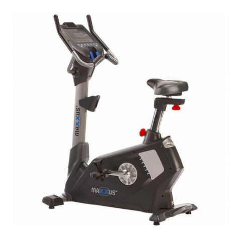
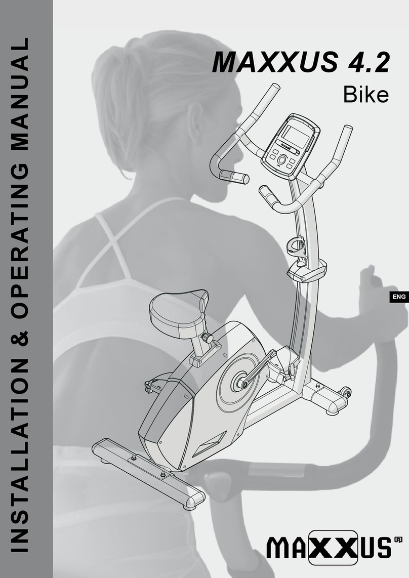
Maxxus 4.2 Installation instructions

ENG
MAXXUS 4.2
Bike
INSTALLATION & OPERATING MANUAL

2
Index
Index 2
Safety Instructions 3
Overall View of the Device 4
Overview - Components 4
Scope of Delivery 5
Fastenings and Tools 5
Assembly 6 - 10
Saddle Adjustment 11
Levelling 11
Transport, Location & Storage 12
Care, Cleaning & Maintenance 12
Mains Cable 13
Cockpit 13 - 19
Heart Rate Measurement 20
Warning on Heart Rate Measurement 21
Pulse Measurement using Hand Sensors 21
Heart Rate Measurement using a Chest belt 21
Training Recommendations 22 - 23
Technical Details 24
Disposal 24
FAQ 25
Accessories 25
Exploded Drawing 26
Parts List 27
Warranty 28
Repairs Contract / Notication oDamage Claim 29
© 2015 by MAXXUS Group GmbH & Co. KG
All rights reserved
This publication may not be reproduced, stored in retrieval system, or transmitted in whole or in part, in any form or by any means, electronic,
mechanical, photocopying, recording, or otherwise, without the prior written permission of Maxxus Group GmbH & Co. KG.
Duplication, including electronic form, is only permitted with prior written permission directly from MAXXUS Group GmbH & Co. KG.
Errors, colour and technical modication are subject to change

3
ENG
Before you start exercising, be sure to read the entire user guide, especially the safety information, the maintenance & cleaning in-
formation and the training information. Take care too that everyone who uses this training device is also familiar with this information
and observes it.
Be sure to carefully follow the maintenance and safety instructions in this manual.
This training device may only be used or its specic purpose. Improper use may present a risk oaccidents, damage to health or
damage to the exercise device. No liability whatsoever is accepted by the distributor for injury or damage caused by improper use.
Power connection
−A mains voltage of 220-230V is required for the operation of the device.
−The exerciser may only be connected to a professionally installed, earthed, 16 A, fused single socket with the mains cable
supplied.
−The training device is switched on and oonly using the ON / OFF switch.
−Always disconnect the power plug from the power outlet when moving the exerciser.
−Before carrying out any cleaning, maintenance or other work, always disconnect the mains plug from the socket.
−When connecting the mains plug, do not use socket strips or cable reels.
−If an extension cable is required, then it must comply with DIN standards, VDE regulations and guidelines, technical rules
issued by other European Union member states or other states which are party to the Agreement on the European Economic
Area.
−Always lay the power cord in such a way that it can neither be damaged nor is a tripping hazard.
−In operating or standby mode, electrical devices such as mobile phones, PCs, Televisions (LCD, plasma, tube, etc.), game
consoles etc. will emit electro-magnetic radiation. For this reason, all these types of devices should be kept away from your
training device as they could lead to malfunction, disturbances or false outputs being shown in heart rate measurements.
Training environment
−Choose a location that oers the greatest possible rm space on all sides othe exerciser. The saety area behind the training
device should be at least 200 cm long and 100 cm wide. Allow at least 100 cm to each side of the training device and 100 cm
in front of the training device.
−Ensure good ventilation and that optimal oxygen is available during exercise.Avoid draughts.
−Your exercise equipment is not suitable for outdoor use, so storage and training is only possible in temperate, clean dry rooms.
−Do not operate or store your training device in wet areas, such as swimming pools, saunas, etc.
−Make sure that your exercise equipment is always mounted on a level clean surface is. Unevenness in the ground must be
removed or compensated.
−To protect delicate oors, such as wood, lamina, tiles, etc. and rom damage such as scratches, it is recommended to put a
oor protection (carpet piece, mat, etc.) permanently under the device. Make sure that the pad is secured against slipping.
−Do not place the exerciser on pale or white carpets, as the feet of the appliance may cause marks.
−Make sure that your exercise equipment, including the power cord, does not come into contact with hot objects and there is a
sufcient saety distance rom any heat source, such as radiators, stoves, open replaces, etc.
Personal safety instructions for training
−The safety key must be correctly inserted before each training session.
−While the exerciser is not in use, remove the safety key and mains cable to prevent improper or unsupervised use by third
parties, such as children.
−You should make a health check with your doctor beore your rst workout.
−If you feel any physical discomfort or experience breathing problems, stop training immediately.- Always start your workouts
with a light load and increase it during the course of your workout evenly and gently. Reduce the load towards the end of your
training session.
−Be sure to wear suitable sportswear and sports shoes during exercise. Note that loose clothing can get caught in the running
belt or rollers during exercise.
−Your exercise equipment can only be used by one person at a time.
−Check whether your device is in perfect condition before every training session. Never use your exerciser if it has any faults or
defects.
−Independent repair work can only be done after agreement and approval from our service department has been received. Only
original spare parts may be used.
−Your exercise equipment must be cleaned after each use. In particular, remove all residues caused by body perspiration or
other liquids.
−Always make sure that liquids (drinks, body sweats, etc.) never enter the vibrating plate or penetrate the cockpit, as this leads
to corrosion and damage to the mechanical and electronic components.
−Your exercise equipment is not suitable for use by children.
−During training, third parties - especially children and animals - must have a sufcient saety zone.
−Before any training, check whether there are objects under your training device and remove them. Never exercise with your
exerciser when there are objects underneath.
−Always make sure that your exerciser is not misused by children as a toy or climbing equipment.
−Make sure that you and third parties never bring body parts close to moving mechanisms.
The construction of this training device is based on the latest technical and safety standards.
This training device should only be used by adults!
Wrong and / or unplanned training can lead to extreme health problems!
Safety Instructions
A B CD E
FGH I J
4
Overview of the Device
No. Description Qty
A Base Frame 1
B Stand, front 1
C Stand, rear 1
D Steering Column 1
E Handlebars 1
No. Description Qty
F Pedals 2
G Bottle Holder 1
H Steering Column Cover 2
I Saddle 1
J Cockpit 1
Handlebars Cockpit
Steering column
Stand with transport wheels
Pulse sensor
Saddle
Stand
Pedal
Scope of Delivery

1
9 12
754
11
8
3
4
2
B37
B36
5
ENG
No. Description Qty
1 Washer, 3/8" 8
2 Bolt, 3/8" 4
3 Bolt, M8x25 4
4 Allen Bolt, M8x25 2
8 Cap Nut, 3/8" 4
No. Description Qty
9 Self Tapping Screw, M5 2
Nachfolgende Schrauben sind bereits vormontiert:
11 Pan Head Screw 4
12 Allen Bolt, M5 2
No. Description Qty
7 Combi Tool 1
5 Allen Key, M5 1
4 Allen Key, M4 1
No. Description Qty
B36 Washer for B37 1
B37 Locking Bolt 1
Fastenings and Tools
Tools may be supplemented or replaced with your own. Make sure that they are an
accurate t.

8
1
CA
2
6
Carefully unpack all parts of the delivery. Two people are required because some parts of your exercise ma-
chine are bulky and heavy. Before mounting, check the completeness of the mounting hardware (screws, nuts,
etc.) and the components in the parts and fastening materials list on the previous pages of this manual.
Carefully carry out the installation, as damage or defects that have arisen due to assembly errors are not
covered by the warranty under any circumstances. Read the instructions carefully before starting, follow the
sequence of the installation steps exactly and follow the instructions for the individual assembly steps. The
installation of the training device must be carried out by responsible adults.
Carry out the installation of your exercise equipment with two adults in a location that is level, clean and free
of obstruction during assembly. Only after assembly of the training device has been completed can training be
started.
Step 1: Mounting the Rear Stand
Attach the rear stand (C) with two 3/8” hexagon head bolts (2), four 3/8” Washers (1), and two 3/8” cap nuts (8)
to the rear mounting of base frame (A)..
Assembly

8
B
1
2
A
D
A
3
7
ENG
Step 2: Mounting the Front Stand
Attach the front stand with transport rollers (B) with two 3/8” hexagon head
screws (2), four 3/8” washers (1) and two 3/8 “cap nuts (8) to the front mount-
ing of the base frame (1).
Step 3: Mounting the Steering Column
Connect the end of the cable that extends from the bottom of the handlebar
stem (D) to the end of the cable that protrudes from the base frame (A). Now
place the handlebar stem (D) on the base rame (A) and x it with our hexa-
gon nuts M8 (3).
WARNING:
When inserting and securing the handlebar stem, make sure that you do not
crush or damage the cables.
Assembly

D
E
4
H
D
A
9
8
Step 4: Mounting the Handlebars
Pass the hand pulse measurement cable, which extends from the bottom of the handlebar (E), in through the
upper, front opening of the steering column (D) and then out from the upper opening. Now lead the two cables
(hand pulse measurement & connection cable) upwards from below through the opening in the handlebar (5).
ATTENTION: Pull out the cables only as far as necessary to connect them to the cockpit later.
Now x the handlebar (E) with two Allen bolts M8 (4) to the steering column (D).
WARNING:
When attaching the handlebar (E), be careful not to crush or damage the cables.
Step 5: Assemble the Steering Column Cover
Place the two parts of the steering column cover (H) on the right and left of the joint between the steering col-
umn (D) and the base frame (A). Secure with two self-tapping screws (9).
Assembly

J
D
11
GD
12
9
ENG
Step 6: Mounting the Cockpit
Loosen and remove the four pan head screws (11) preassembled on the back of the cockpit (J). Connect the
cables that protrude from the cockpit (J) with the cables that protrude from the handlebars. Carefully check the
cable connections. Carefully push the excess cables back into the handlebar stem (D). Now secure the cockpit
(J) to the handlebar shaft with the four pan head screws (11).
Warning:
When attaching the cockpit (J), make sure that you do not crush or damage the cables.
Step 7: Mounting the Botle Holder
Loosen and remove the two M5 Allen screws (12) on the handlebar stem (D) and use them to attach the bottle
holder (G) to the handlebar stem (D).
Assembly

I
B36
B37
A03
F
10
Step 8: Mounting the Saddle
Attach the saddle (I) to the adjustable bracket of the seat support (A03) with the locking screw (B37) and the
washer (B36).
Step 9: Mounting the Pedals
Insert the right pedal (F) thread into the right pedal arm socket and tighten it clockwise. Insert the left pedal (F)
thread into the left pedal arm socket and tighten it anti-clockwise.
Assembly

B37
Position A
Position B
11
ENG
Horizontal Adjustment
You can adjust your saddle horizontally to set your optimum distance to the
handlebars. Loosen the hand lever (B37) below the saddle by turning it an-
ti-clockwise. Move the saddle to the desired horizontal position and retighten
the hand lever (B37) clockwise.
Vertical Adjustment
You can adjust the saddle position vertically to set your optimum distance to
the pedals. Loosen the knob located on the saddle support of the main frame
by turning it anti-clockwise.
WARNING:
Please note that the knob operates a quick-release system. You only have
to turn it anti-clockwise 2-3 times to unlock it, then pull on the knob to quick
release the saddle support. Hold the knob in this pulled position and then set
the desired saddle height. Let go of the knobl to engage the locking mech-
anism again. To do this, you may need to move the seat tube slightly up or
down to engage the mechanism in the corresponding seat support hole.
Tighten the knob clockwise again.
Setting the optimum saddle height:
Make sure you are wearig the shoes you want to wear during your work-
out. Comfortable running shoes or sports shoes are ideal. Adjust the pedal
position so that the right pedal arm is pointing vertically down and the right
pedal is at the lowest point of its radius of motion. Now sit on the saddle and
place the heel of your right foot on the right pedal. Your leg should be almost
completely straight. Adjust the saddle height until your right leg is almost fully
extended and then put the ball of the foot on the pedal. Now your leg should
be slightly bent. This is the ideal height adjustment for your saddle.
WARNING:
Never train with a seat height adjustment that fully extends your legs at the
lowest position of the pedals.
Make sure that your exercise equipment is always level. In order to compen-
sate or minor bumps or slopes, adjustable eet are tted right and let on the
front and rear stands and on the sliding. To ensure that the device stands
level, rst turn all eet to the lowest position (position A). Inecessary, adjust
the feet so that the training device is level and stable.
Ithe adjustment range othe adjustable eet is not sufcient to allow level
standing of the training device, please check the surface of the location. If
necessary choose a dierent location where a sae and level position othe
training device is ensured.
Saddle Adjustment
Levelling
Adjustable foot Adjustable foot

12
Transport
In order to transport your training device simply and safely, the front stand is equipped with transport rollers.
To move the exerciser, stand in front of the handlebars and grab them with both hands. Pull the training device
gently towards you and lower the handlebars until the rear stand no longer has contact with the ground and the
main weight of the exerciser is resting on the transport rollers. Now you can simply pull the exercise machine
along on the transport rollers and into the desired position. When lifting, transporting and positioning the device
always make sure that you have a secure footing.
Location & storage
This training device was designed for exclusive use in dry, well-ventilated indoor areas. The use or storage in
damp or wet areas, such as saunas, swimming pools, etc. and in outdoor areas, such as balconies, terraces,
gardens, garages, etc. is excluded.
These locations may give rise to electronic defects, corrosion and rust due to the high humidity and low temper-
atures prevailing there. Under no circumstances will any claims for damages of this kind be accepted under the
warranty.
Please choose a dry, level and warm place to store your training device. For your own sake, also make sure that
you choose a training area which is sufciently ventilated to ensure optimum oxygenation during training.
Before putting your training device back into operation after a long period of non-use, make sure that all fasten-
ings are secure.
WARNING
Before starting cleaning, maintenance and / or repair work, the exerciser must be completely discon-
nected from the power supply. This will only be the case if the power cable is disconnected from the
power outlet and the exerciser. Thereore, rst disconnect the power plug rom the power outlet, and
then disconnect the power cable from the exerciser. The mains cable may only be reconnected to the
training device and the power supply when all work has been completed and the proper training condi-
tion of the device has been restored.
Cleaning
Clean your exerciser after each workout. Use a damp cloth and soap.
Never use solvents.
Regular cleaning contributes signicantly to the preservation and longevity oyour training device.
Damage caused by sweat or other liquids is not covered by the warranty under any circumstances. During train-
ing, make sure that no uid can enter the exercise machine or the computer.
Maintenance
Sealed bearings are used in your training device, lubrication of the bearings is not required.
Checking the fastenings
Check tightness of nuts and bolts at least once a month and re-tighten them if necessary
Checking the components
Before each workout, check that the saddle, seat support, handlebars and pedals are securely fastened.
WARNING:
Never train if one or more of these components are loose.
Transport, Location & Storage
Transport wheels
Care, Cleaning & Maintenance

13
ENG
Mains Cable
Insert the connector of the power cable supplied into the socket located on the rear of the main housing. Then
connect the mains cable to a power socket.
WARNNG
This device is only to be connected to an earthed socket installed by a qualied electrician. Do not use a socket
strip. If an extension cable is required, then it must comply with DIN standards, VDE regulations and guidelines,
technical rules issued by other European Union member states or other states which are party to the Agreement
on the European Economic Area.
Connecting the device
ACHTUNG:
Before connecting the mains adapter to the device, always check that it is the mains adapter supplied with the
device. Using a dierent mains adapter may damage the electronic components othe device, or which the
manufacturer assumes no liability.
Always connect the power cable to the exerciser before connecting it to a power outlet. If you want to discon-
nect your exerciser rom the power supply, always disconnect the power cable rom the mains rst.
Switch on the device
First connect the power cable to the exerciser and then connect the mains cable to the power socket, the cock-
pit turns on automatically. If the training device is already connected to the mains, but the cockpit is in stand-by
mode, activate the cockpit by pressing any key or by moving the pedals.
Turn of the device
When inactive for more than 4 minutes, the cockpit automatically switches to stand-by mode. Once you have
nished your workout you should always disconnect the exerciser rom the mains. Always unplug the mains
cable rom the wall socket rst and then remove the power cable.
Mains Cable & Connection
Cockpit
LCD-Display
Control keys
Recovery heart rate
Control keys
Storage compartment for smartphone, tablet PC, etc.
USB connection for
charging cable

14
Functions
The cockpit has 6 function buttons: UP, DOWN, RESET, START/STOP, RECOVERY and MODE.
A. UP : Selection of the function and increase of values.
B. DOWN : Selection of function and decrease of values.
C. RESET: Reset in Stop Mode.
D. START/STOP : Start and stop programs.
E. RECOVERY : Recovery pulse test function.
F. MODE : In Stop Mode to conrm inputs and access the training program.
Display
Switching on: Plug the power adapter into the power socket of the bike and connect it to the mains (230V). The
display shows all segments of the cockpit for about 2 seconds.
A. Level : Displays the resistance levels (LEVEL 1 to LEVEL 16).
B. Resistance proles:
20 Resistance columns in 8 rows are displayed.
C. Time display:
D. Display of speed and revolutions (RPM)
Cockpit

15
ENG
E. Display of power in watts and load:
F. Information display: display of information text
G. Calories:
H. Distance display:
I. Pulse display :
Display of the measured pulse or heart rate
Readings
TIME Display range 0: 00 ~ 99: 99; Adjustment range 0: 00 ~ 99:
00.
DISTANCE Display range 0.00 ~ 99.99; Adjustment range 0.00 ~
99.90km.
CALORIES Display range 0 ~ 9999; Adjustment range 0 ~ 9990.
PULSE Display range P-30 ~ 230; Adjustment range 0-30 ~ 230.
WATT Display range 0 ~ 999; Adjustment range 10 ~ 350.
SPEED 0.0~99.9km.
RPM 0~999.
Cockpit

16
Quick-Start
If you press the START key immediately after switching on, the training time starts to run. You can adjust the
resistance levels individually by pressing the UP / DOWN keys. Since no training values are dened in this type
of training it must be stopped by the user.
Important instructions
A. All displays are for training purposes and are not intended for medical use.
B. Please note that only one value, time or distance, can be pre-selected in the program. If both values
are selected, the cockpit displays 0:00.
Program Operation
A. Manual Training:
In this program you set the resistance manually.
Pre-sets such as time, calories, heart rate or distance are possible.
1. Press UP or DOWN to select the program. Select “Manual” and press MODE to enter the pro-
gram.
2. Press UP or DOWN to select TIME, DISTANCE, CALORIES, PULSE and press MODE to con-
rm.
3. Start the training with the START / STOP key. Set the resistance with the UP or DOWN keys.
4. To pause the workout or start it again, press the START / STOP key. In stop mode, you can
return to the main menu by pressing the RESET key.
B. Program selection with xed training prole:
1. Use the UP or DOWN keys to select the desired program and conrm with the MODE key.
2. Ithe training time is to be preselected, press the UP or DOWN key and conrm the entry with
the MODE key.
3. Start the training with the START / STOP key. Set the desired resistance with the UP / DOWN
keys.
4. To pause the workout or start it again, press the START / STOP key. In stop mode, you can
return to the main menu by pressing the RESET key.
Cockpit

17
ENG
C. USER Program: Create your own program prole.
1. Select the user program with the UP or DOWN keys and conrm the selection with the MODE
key.
2. Set the resistance with the UP or DOWN keys and switch to the next segment with the MODE
key. Select the desired resistance again with the UP / DOWN keys and conrm with the MODE
key until the desired prole is created.
3. Hold down the MODE key to exit program input.
4. Press the UP or DOWN key to select the time and conrm the selection with MODE.
5. Start the program with the START / STOP keys. If necessary, change the resistances with the UP
or DOWN keys.
6. To pause the workout or start it again, press the START / STOP key. In stop mode, you can
return to the main menu by pressing the RESET key.
D. H.R.C. Heart Rate Program: (Use an uncoded wireless heart rate chest belt!)
1. Select the program with the UP or DOWN keys and conrm the selection with MODE.
2. Select your age with the UP or DOWN keys and conrm the entry with MODE.
3. Use UP or DOWN to select the level in which you want to train: 55%, 75%, 90%, or DAY (target
H.R.) and conrm with MODE.
4. Select the desired exercise time with the UP or DOWN keys and start the program with the
START / STOP key.
5. To pause the workout or start it again, press the START / STOP key. In stop mode, you can
return to the main menu by pressing the RESET key.
Cockpit

18
E. WATT program:
1. Select the Wattsg program with the UP or DOWN keys and conrm the selection with MODE.
2. Select the desired WATT perormance with the UP or DOWN keys and conrm with MODE.
3. Select the desired exercise time using the UP or DOWN keys.
4. Start the training with the START / STOP key. Change the power with the UP / DOWN keys.
5. To pause the workout or start it again, press the START / STOP key. In stop mode, you can
return to the main menu by pressing the RESET key.
Program
Cockpit

19
ENG
F. Recovery function:
Determine the current tness level by measuring the recovery pulse.
1. While the recovery function is in progress, the pulse must be measured by the two hand pulse
sensors. When the pulse is displayed, press the RECOVERY key to start the measurement. Do
not cycle during measurement!
2. A countdown timer runs from “0:60” seconds to “0:00”.
3. Ater measurement, the display shows the tness value F1 to F6, where F1 is the best value and
F6 the worst value.
1.0 Outstanding
1.0 < F < 2.0 Very t
2.0 < F < 2.9 Good
3.0 < F < 3.9 Sufcient
4.0 < F < 5.9 Below average
6.0 Poor
Storage compartment for smartphone / tablet PC
There is a storage compartment on the ront othe cockpit which ts most current smartphones and tablet PCs.
Please check beore use iyour Samrtphone or Tablet PC ts in the storage compartment securely.
USB port
A USB port is tted on the side othe cckpit. The user can connect a USB charging cable or their smartphone /
tablet PC to charge it as needed. The USB charging cable is not included!
Cockpit

200
150 195
130 146 190
110 127 143 185
107 124 139 180
105 120 135 175
102 117 131 170
99 114 128 165
96 111 124 160
94 107 120 155
91 104 116 150
88 101 113 145
85 98 109 140
83 94 105 135
80 91 101 100
77 88 98
74 85
72
20 25 30 35 40 45 50 55 60 65 70 75 80 85 90
20
Heart Rate Monitoring
Calculating your personal heart rate when training
Calculate your personal heart rate when training as follows:
220 - Age = maximum heart rate
This value represents your maximum heart rate and serves as a basis from which to calculate
your personal training heart rate. Set the calculated heart rate at 100%
Wellness and Health - target zones = 50 to 60% of the maximum heart rate.
This training zone is ideally suitable for people who are over-weight and/or older beginners, or people starting again after a longer
break from training. Training in this zone the body will burn approx. 4-6 calories per minute to produce energy.
The percentage ratio per calorie is approx. 70% fat, 25% carbohydrate, and 5% protein.
Fat burning - target zone = 60 to 70% of the maximum heart rate
This training zone is suitable for athletes and sports people who aim to lose weight.
Training in this zone the body will burn approx. 6-10 calories per minute to produce energy.
The percentage rate per calorie is approx. 85% fat,10% carbohydrate, and 5% protein.
Condition & Fitness - target zone = 70 to 80% of maximum heart rate
This training zone is ideally suitable for athletes and sports people who aim to improve their stamina and/or condition.
Training in this zone the body will burn approx. 10-12 calories per minute to produce energy.
The percentage rate per calorie is approx. 35% fat,60% carbohydrate, and 5% protein.
For optimum eects in training results you should calculate the average value othe selected target zone (also see above table):
Wellness & Health - target zone average value = 55% of maximum heart rate
Fat burning - target zone average value = 65% of maximum heart rate
Kondition & Fitness - target zone average value = 75% of maximum heart rate
Heart Rate per Minute
Age
of maximum heart rate
100%
75%
65%
55%
Other manuals for 4.2
1
Table of contents
Other Maxxus Exercise Bike manuals

Maxxus
Maxxus 6.2 Installation instructions

Maxxus
Maxxus 90R Pro Installation instructions

Maxxus
Maxxus PRO SPK-21 User manual

Maxxus
Maxxus 4.2R Installation instructions

Maxxus
Maxxus SpeedBike SX3 Installation instructions

Maxxus
Maxxus RunMAXX 90 PRO Installation instructions

Maxxus
Maxxus PRO SPK-23 User manual

Maxxus
Maxxus 4.2 Installation instructions

Maxxus
Maxxus 4.2R User manual

Maxxus
Maxxus SpeedBike S1 Installation instructions