Maytronics MINERAL SWIM O3 User manual

MINERAL SWIM O3, MINERAL SWIM PRO1,
MINERAL SWIM PRO2, MINERAL SWIM PRO3
USER
MANUAL
v1

USER MANUAL
23
WARNING
This appliance is not intended for use by
persons (including children) with reduced
physical, sensory or mental capabilities,
or lack of experience and knowledge,
unless they have been given supervision
or instruction concerning the use of the
appliance by a person responsible for their
safety. Children should be supervised to
ensure they do not play with the appliance.
Do not open the Mineral Swim control unit.
There is no user-serviceable parts in the
control box. Repairs are only to be made
by a Maytronics authorised technician. If
the supply cord is damaged, it shall only be
replaced by the manufacturer or its service
agent or a similarly qualified person to
avoid a hazard.
Do not operate the electrolytic cell without
proper flow or water circulation as this may
cause damage to the unit.
CAUTION
This unit is not intended for use with
temporary or fold-able/storable pools. All
pipe-work associated with this system is
intended to be fixed and should remain
intact following installation by qualified
personnel.
Important Safety Information
Congratulations on your choice of a Mineral Swim pool purification system
for your swimming pool. Mineral Swim is designed for easy and simplistic
operation and maintenance.
Please take the time to read these instructions thoroughly before
attempting to operate your unit. Should you require additional information
or further assistance, do not hesitate to contact your local Mineral Swim Pro
representative or visit our website www.mineralswim.com.au
If you are using this system for a pool with an integrated spa, you
may require a de-gas vessel if the pool return goes to the spa first.
Alternatively, your installer may fit a flow switch to idle the system while
the spa is in use.
For installations where the filter/chlorination system is below the level of
the pool, a drain valve must be fitted to keep the ozone outlet line dry
should any water backflow through the line. This drain valve is available
from Maytronics.
Mineral Swim
Pools with a Spa
Equipment Below Water Level
This manual contains important information about the
operation and safe use of this product. Read and follow all
instructions. Important safety instructions pertaining to a
risk of fire, electric shock, or injury to persons.

USER MANUAL
45
CONTENTS
Important Safety Information ....................................................................... 2
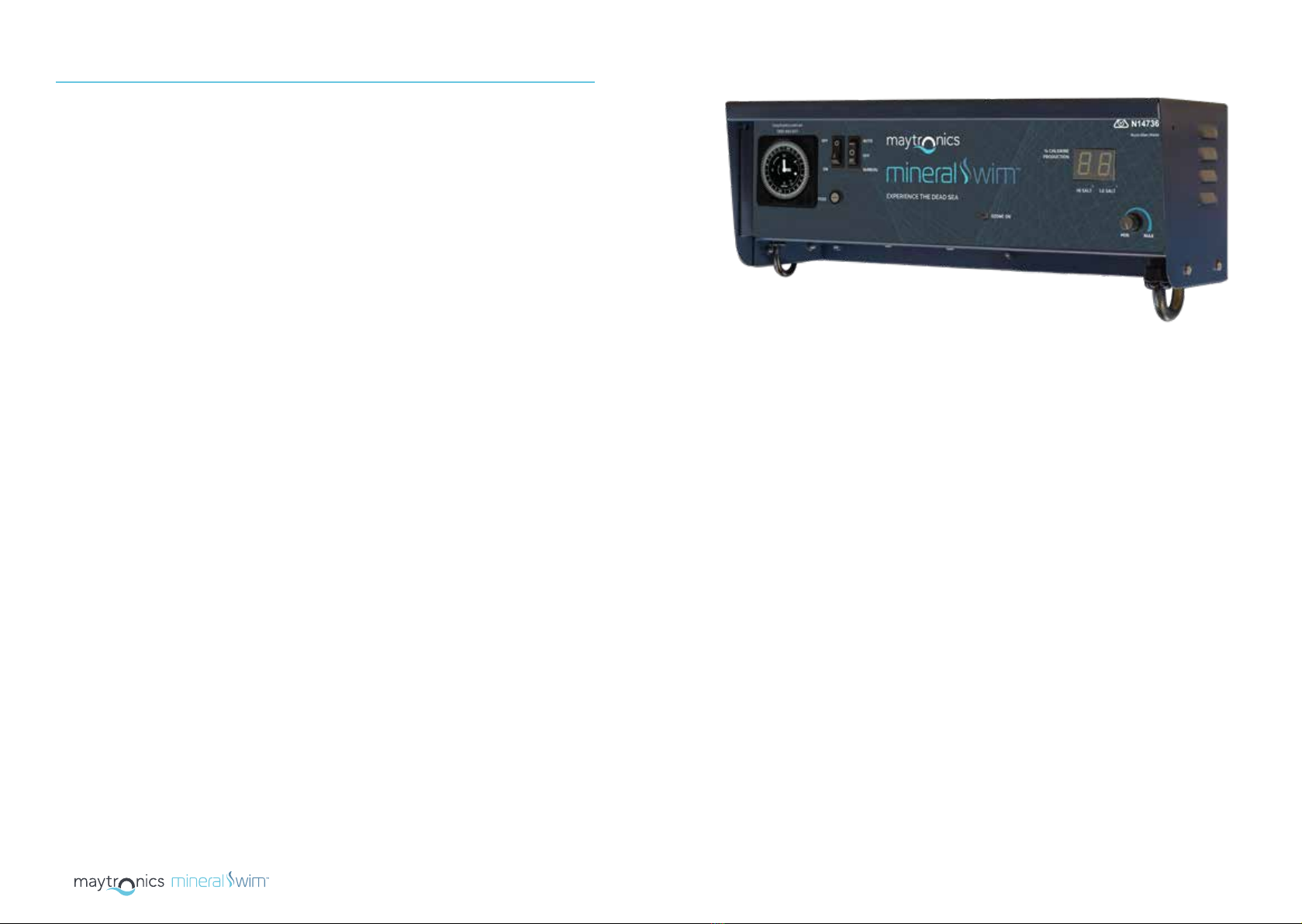
Control Unit Features ......................................................................................... 6
INSTALLATION ...................................................................................................... 8
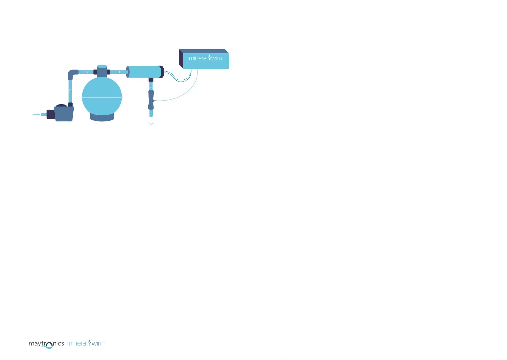
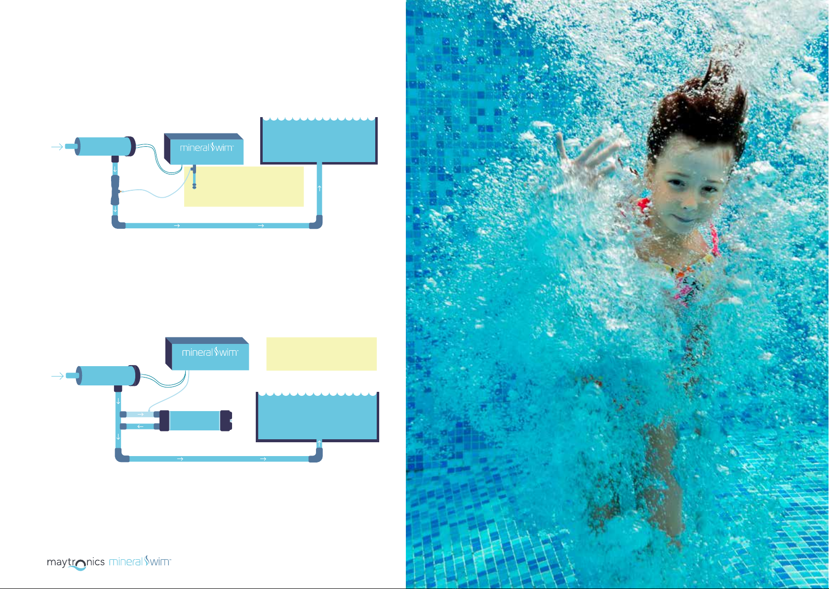
Installation Guide ................................................................................................. 9
Important Notes ................................................................................................... 12
OPERATIONS ........................................................................................................... 15
Operating Instructions ...................................................................................... 16
MAINTENANCE ..................................................................................................... 20
Maintenance .......................................................................................................... 21
Water Chemistry (Balancing Information) ............................................. 21
WARRANTY .............................................................................................................. 22
Warranty Information ........................................................................................ 23
TROUBLESHOOTING ............................................................................................. 24
Troubleshooting ..................................................................................................... 25
Copyright Noce: Copyright 2021 by Maytronics Australia. All rights reserved. No parts
of this publicaon may be reproduced, transmied or stored in a retrieval system in any
form or by any means, electronic, mechanical, photocopying, recording, or otherwise,
without the prior wrien permission of Maytronics Australia. Warnings: These products
must be installed by a qualied installer. These products may not perform as expected if
installed incorrectly. Water quality needs to be regularly tested. Please consult your pool
supplier for further details about water tesng procedures. Failure to correctly connect
will result in damage to the Ozone Cell which will void the warranty. Ensure ow is
correct. Ensure that you have dry hands when operang these products. These products
are designed and tested to conform to AS/NZS. 3136 - AS/NZS 3100. To comply
with this standard the chlorinator must not be installed in the pool zone. Trademarks:
Throughout this document trademark names may have been used. Rather than placing a
trademark symbol in every occurrence of a trademark name, we state that we are using
the names only in an editorial fashion and to the benet of the trademark owner with
no intenon of infringement of the trademark. Noce of Liability: While every eort
has been taken to ensure the accuracy of this document, neither Maytronics Australia
nor any of its ocial representave shall have any liability to any person or enty with
respect to any liability, loss or damage caused or alleged to be caused directly or indirectly
by the informaon contained in this guide. Should you nd any error or inconsistency,
please nofy us accordingly. Maytronics Australia reserves the right to make changes to
features and specicaons at any me without prior nocaon in the interest of ongoing
development and improvement.
Not for use in commercial pools. Use in commercial pools may result in warranty being
invalidated. For use in commercial applicaons, please contact Maytronics Australia on
1300 693 657.

USER MANUAL
67
1Ozone Run Indicator 4Air Filter
2Fuse 5Ozone Output
3Master Switch 6Pump Outlet Socket
Mineral Swim O3
*Mineral Swim O3 does not have a chlorinator.
4
5
3
1
Mineral Swim PRO1, Mineral Swim PRO2, Mineral Swim PRO3
* Mineral Swim PRO1, Mineral Swim PRO2, Mineral Swim PRO3 units come with an integrated chlorinator.
1Ozone Run Indicator 8Air Filter
2Chlorine Cell Output Display 9Ozone Output
3Fuse 10 pH Drive Socket (12V plug)
4Master Switch 11 Positive Cell Lead (Red)
5Sanitation Switch 12 Negative Cell Lead (Black)
6a Chlorine Cell Output Control (0-99) 13 Gas Sensor Connector (White)
6b Push menu for e-Series – Dosage menu
(d0-d9 & Pr-Prime) 14 Timer
7Pump Outlet Socket
14
4 5
3
7
89
11
12
13
1
26a
10
6b
Control Unit Features
6
2

USER MANUAL
89
INSTALLATION
Note: Install the Mineral Swim control unit a minimum of 900mm above ground level in an area protected
from the elements to eliminate possible damage from severe weather conditions.
(If system is below water level, install drain valve as per instructions).
Step 1:
Predilute the required dose of Ecoclear® Shield & Swim in 10L of water, and evenly broadcast
across the pool surface.
Step 2:
Mount Mineral Swim control unit a maximum of 1.5 metres from the filter. Fit two screws
(supplied) into control unit wall bracket and hang control unit.
Step 3:
Plumb ozone injection manifold after chlorine cell on the return to the pool; ensuring the
direction of the ozone injection manifold is correct (arrow indicated direction of water flow).
The manifold should be last on the return line, after all other equipment is installed.
Step 4:
Leave plumbing to cure for a 24 hour period for best results.
Step 5:
Connect supplied Teflon tubing from the control unit (see label on Teflon tubing for direction
ensuring non-return valve is in the correct direction) to the ozone injection manifold by
connecting to the compression fitting on the venturi.
Step 6:
Plug the Mineral Swim control unit power cord into the sanitation system (chlorinator/dosing
system). The pool pump should be plugged into the under casing of Mineral Swim control
unit. Set master switch to ON. The Mineral Swim control unit will be controlled by the existing
chlorinator/dosing system.
Note: If using a chlorinator, always ensure your pump is running, never allow your chlorinator to operate
without the pump running.
Mineral Swim O3
These products must be installed by a qualified installer.
Installation Guide
VENTURI
PUMP
MEDIA FILTER
CHLORINATOR
CELL
return
to pool
from
pool
CHLORINATOR CONTROL UNIT

USER MANUAL
10 11
Mineral Swim PRO1, Mineral Swim PRO2,
Mineral Swim PRO3
Note: Install the Mineral Swim control unit a minimum of 900mm above ground level
in an area protected from the elements to eliminate possible damage from severe
weather conditions. (If system is below water level, install drain valve as per instruc-
tions).
Step 1:
Predilute the required dose of Ecoclear® Shield & Swim in 10L of water, and
evenly broadcast across the pool surface.
Step 2:
Mount Mineral Swim control unit a maximum of 1.5 meters from the filter
and chlorine cell. Fit two screws (supplied) into control unit wall bracket and
hang control unit.
Step 3:
Plumb chlorine cell onto return pipe after filter, ensuring there is a gas trap
(see images below).
Step 4:
Plumb ozone injection manifold after chlorine cell on the return to the pool;
ensuring the direction of the ozone injection manifold is correct (arrow
indicated direction of water flow). The manifold should be last on the return
line, after all other equipment is installed.
These products must be installed by a qualified installer.
Step 5:
Connect the chlorine cell cable to the three colour coded terminals located
on chlorine cell. (Terminals need to be slightly crimped for snug fit).
Step 6:
Ensure pool water is correctly balanced, plus appropriate salt/mineral
levels are achieved (3500 - 4500ppm) and dissolved. (Confirm with builder/
supplier that chemicals can be added to the pool).
Step 7:
Leave plumbing to cure for a 24 hour period for best results.
Step 8:
Set timer on Mineral Swim control unit to recommended run time for pool
size and environment (refer to page 17).
Step 9:
Plug pump power cable into Mineral Swim control unit below timer. Set
the master switch to ON, and sanitation switch to MANUAL. Ozone run
indicator should be illuminated. Check all plumbing for visible leaks.
Step 10:
Adjust the chlorine cell output to recommended output.
Note: We recommend running your system at maximum output for the first 24
hours of operation.
Step 11:
Set the sanitation switch to the AUTO position.
VENTURI
PUMP
MEDIA FILTER
CHLORINATOR
CELL
return
to pool
from
pool
CONTROL UNIT

USER MANUAL
12 13
Important Notes
Chlorinator Cell Housing Installation
The Mineral Swim Pro Series cell housing must be plumbed into the return
line of the pool filter system after the filter and any diversion valves.
In situations where a heater is incorporated, the Mineral Swim Pro Series
cell housing must be installed after the heater. Should a solar heating
system be installed, the housing must be plumbed after the solar
diverters and after the water exits the solar system and re-joins the main
stream pool return line. Ensure there is a gas trap by always installing the
chlorinator cell at a higher level than the filter (see below).
CHLORINATOR
CELL
MEDIA FILTER
CHLORINATOR
CELL
CARTRIDGE
FILTER
CHLORINATOR
CELL
CARTRIDGE
FILTER
SAFESAFE
DANGEROUS
Pump Outlet Socket
A 240 volt pump output power socket is supplied and located on the left-
hand underside of the Mineral Swim control unit. Your pool pump power
supply lead should be plugged into the socket so that when the time clock
switches at the designated times both the Mineral Swim control unit and
the pump will activate in unison.
The pump socket is designed to operate a single pool pump of maximum
1.5 hp (horse power) only. On rare occasions, a 2hp pump will be used as
an integrated solution for in-floor and pool filtration. Do not attempt to
operate any equipment other than your pool pump from this socket as
damage might occur to the Mineral Swim control unit that is not covered
under warranty.
Standard "Non-Flooded" Installation*
from
filter
CHLORINATOR
CELL
VENTURI
POOL
return to pool
Mineral Swim control unit must be
mounted above water level. For
below water level installs, see
“Flooded” installation instructions.
CONTROL UNIT
* Diagram is for illustration purposes only. Does not include all required swimming pool equipment.
For installations where control unit is above water level.

USER MANUAL
14 15
"Flooded" Installation*
For installations where control unit is below water level.
from
filter
CHLORINATOR
CELL
VENTURI
DRAIN VALVE
POOL
return to pool
If water level is above the
Mineral Swim control unit,
a drain valve must be
fitted.
CONTROL UNIT
Installation with De-Gas Chamber*
from
filter
CHLORINATOR
CELL
POOL
return to pool
Mineral Swim control unit must be
installed above water level, or a
drain value installed.
DE-GAS VESSEL
INJECTION
MANIFOLD
CONTROL UNIT
* Diagram is for illustration purposes only. Does not include all required swimming pool equipment.
OPERATIONS

USER MANUAL
16 17
Operating Instructions
It is essential that a new pool is balanced correctly. Consult your pool
builder or an authorised pool technician on how to achieve this. You can
find the water chemistry parameters on page 21 of this manual.
New Pools
Achieving The Correct Salt/Mineral Levels
For best results, the salt/mineral concentration in the pool water is
required to be within an average range of approximately 3,500 to
4,500ppm. Check salt/mineral supplier's guide for achieving correct ppm.
Existing Pools
To establish the salt level in an existing pool, take a water sample to your
local pool shop for testing, they will tell you the current salt/mineral levels
(TDS) and advise the correct course of action required.
Sanitation Switch
O The system will not operate.
Auto The time clock will automatically switch your pool
equipment on or o at your designated times.
Manual The timer is by-passed, the system will operate all
functions permanently.
• Set the master switch to the “ON” position.
• Set the sanitation switch to “MANUAL” position to turn the unit on.
• Once the salt/minerals have been added and dissolved turn the cell production
dial to the required position based on the season and the size of the pool (set
to max output to start with and adjust down as required).
• Set the timer to run for the recommended times (4-6 hours for winter / 8-10
hours for summer). Switch the system to AUTO and the unit will now be
controlled by the timer.
• To set current time, rotate minute hand clockwise until arrow head aligns with
correct time.
Note: This will need to be reset whenever the power is disconnected from the unit
and for daylight saving time changes.
Note: Only rotate clockwise to set. Rotating incorrectly will damage the time clock.
• To set ON/OFF times, move required tappets to appropriate position. Inner
position for OFF and outer position for ON.
Note: Proper operation requires that the appropriate switch settings below are
enabled.
• Each of the tappets on outer edge of the timer represents 15-minute intervals.
Note: If you require your Mineral Swim Pro Series to be connected to an o-peak
tari we recommend the use of an appropriate battery backup time clock for that
purpose.
Salt/Mineral Requirements
Mineral Swim PRO1, PRO2 and PRO3 control units require 3,500-4,500ppm
salt/mineral levels. Using only refined swimming pool salt or minerals, add
the desired quantity to the swimming pool water. To assist in the rapid
dissolving and mixing, sweep or brush the solids until they are fully dissolved.
Note: Undissolved salt/minerals may result in staining of your pool’s interior walls.

USER MANUAL
18 19
Checking Chlorination Output
The chlorine cell output controller regulates the amount of chlorine
production relevant to the position it has been set to. By adjusting the cell
output controller clockwise, you increase chlorine production and by turning
anti clockwise you reduce production. Do not attempt to turn the controller
beyond its stopping positions as this could cause damage to your unit that
is not covered by warranty.
To ensure your chlorinator is working correctly, follow the steps below:
• Ensure the cell production is at maximum.
• With the unit running take a sample of water from the skimmer box and
conduct a chlorine test, note the result.
• Take a sample of water directly in front of the return to the pool outlet and
conduct a chlorine test, note the result.
• If the latter is higher in chlorine than the first test, your Mineral Swim Pro Series
is eciently producing chlorine (if not please see troubleshooting).
To ensure your Mineral Swim control unit ozone production is functioning,
follow the steps below:
• Check that the green ozone run indicator is illuminated.
• Check that there is suction at the air filter on the bottom of the power pack.
• Check there is bubbles at the return jets when the system is running.
Checking Ozone Output
Chlorine Cell Output Display Definitions
Mineral Swim PRO1, Mineral Swim PRO2, Mineral Swim PRO3
The Mineral Swim PRO control unit is fitted with a digital display. During
operation, the digital display will illuminate relevant to the degree at which
the chlorine output control has been set. You can increase or decrease
chlorine output to suit your pool’s requirements. As you increase the
output (by turning the control knob clockwise), the display will indicate the
percentage of full production capacity (0-99%) reading to the cell. You have
full control of chlorine production; merely by adjusting the controller to
satisfy your chlorine demand.
The Mineral Swim PRO also has on board diagnostics to indicate any issues
with the system (see table below for definitions).
0-99 A value in the range of 0-99 indicates the output percentage of
the system.
OF Cell output control knob is turned o, the Mineral Swim Pro Series
chlorination has been manually switched o.
dg Automatic cleaning cycle beginning, the self-cleaning function is
beginning. This is only displayed for a short period.
Pb (Flashing) There is insucient water flow through the cell to
produce. If this persists, please refer to troubleshooting.
OL (Flashing) Overload condition (see troubleshooting).

USER MANUAL
20 21
MAINTENANCE
Every 12 months or as required
The Teflon check valve prevents water from returning to the system. Flooded
systems (below water level) require a water trap (drain valve) to protect the
system in the event that the check valve fails. To replace the check valve
simply pull the delivery line o the check valve at both ends and replace with
new check valve.
Maintenance
Regular water testing must be performed to ensure the water is within the
recommended ranges (see below):
Chlorine 1 – 3 ppm
pH Fibreglass: 7.0 – 7.2
Concrete: 7.2 – 7.6
Total Alkalinity 80 – 120 ppm
Calcium Hardness Fibreglass: 175 – 225ppm
Concrete: 275 – 325ppm
Cyanuric Acid (CA) 30 – 50 ppm
Phosphates 0 – 300 ppm (or as per chlorinator
manufacturer's instructions)
TDS 3500 – 4500 ppm
Water Chemistry (Balancing Information)
Replacing The Ozone Check Valve
Ozone Filter Replacement
Electrode (Cell) Cleaning
Regularly (every 3-6 months)
Replace the ozone air filter located under the control unit. To remove the filter
turn it anticlockwise, remove the old cotton wool and replace with half a standard
cotton wool ball. Only hand tighten the filter when refitting.
Although you have a reverse polarity (automatic cell cleaning) system, it is
recommended from time to time that the cell be checked for any accumulation
of calcium or other deposits that may have built up. We recommend cleaning
the cell once or twice a year subject to your pool’s application and location.

USER MANUAL
22 23
WARRANTY
Mineral Swim control systems have:
• 3 year parts replacement warranty (1 YEAR IN-FIELD) on the control box,
electronics and seals.
• 6 year pro-rata warranty of chlorinator cell. (Mineral Swim PRO1, Mineral
Swim PRO2, Mineral Swim PRO3 series only).
• 10 year (1 YEAR IN-FIELD) warranty on the ozone production corona
discharge unit.
• Stainless Steel Tube.
Activate your Mineral Swim warranty by registering at:
maytronics.com.au/support/registration
Warranty Information
Glass Tube
3 Year Warranty
Ozone PCB
3 Year Warranty
Stainless Tube
10 Year Warranty
O-Rings
3 Year Warranty
6
Y
e
a
r
C
e
l
l
W
a
r
r
a
n
t
y
*
3
Y
e
a
r
F
u
l
l
W
a
r
r
a
n
t
y
10
Year Ozone Cell
Warranty

USER MANUAL
24 25
TROUBLESHOOTING
Troubleshooting
Fault Potential Causes Action Required
Cell output display flashing
“Pb” continuously (no water
flow)
• Pump, blocked, turned o
or disconnected
• Valves closed
• Gas sensor wire at cell
disconnected
• Ensure pump is on and no
flow obstructions
• Ensure correct valves are open
• Reconnect sensor wire at cell
Low salt indicator flashing
• Salt/mineral level in pool has
dropped too low
• Pool water temperature
is low
• Cell has calcified
• Cell has failed
• Take sample of water to pool
shop and check salt/mineral
level. Add salt/minerals as
recommended
• Add salt/minerals and reduce
chlorinator output until the
water is warmer
• Ensure cell is clean
High salt indicator flashing • Too much salt/minerals has
been added to the pool
• Take a sample to your local
pool shop to confirm salt/
minerals levels and remove
and replace water as
required
No display
• No mains power
• Mineral Swim control unit
plug removed from power
point
• Mineral Swim control unit
fuse blown
• Unit is turned o
• Ensure there is mains power
available
• Ensure Mineral Swim control
unit is plugged into power
point and it is turned on
• Check fuse condition and
contact technician if blown
• Ensure manual mode and
sanitation are switched on
Low/no chlorine
• Insucient run times
• Incorrect cell production setting
• Low/high salt/mineral levels
• Loose connections at the cell
(red & black)
• Water chemistry
• Adjust run times to allow
more production
• Increase cell production
• Check/adjust salt/mineral
levels to be within required
range
• Disconnect leads, then
reconnect leads firmly
• Take water sample to pool shop
Ozone run indicator not
illuminated
• Water chemistry issue
• LED failed
• Ozone module failed
• Take water sample to pool
shop
• Contact Maytronics
authorised technician
Cell output flashing “OL”
• Possible short circuit in cell
(debris)
• Extremely high salt/mineral
levels
• Remove cell and check for
any debris and clean
• Check and adjust salt/mineral
levels
Water dripping out of drain
valve (flooded systems) • Teflon check valve has failed • Replace Teflon check valve

mineralswim.com.au
This manual suits for next models
3
Table of contents
Popular Lighting Equipment manuals by other brands

Assurance Emergency Lighting
Assurance Emergency Lighting RHB1201 instruction manual

Champlain
Champlain ACM-123-2 quick start guide

Hubbell
Hubbell NXP2 Series quick start guide

Image Engineering
Image Engineering lightSTUDIO user manual

NA
NA SAL SLIM AREA LIGHT installation guide

MJ LED LIGHTNING
MJ LED LIGHTNING WIRELESS BATTERY PAR 910 user manual

NVC
NVC SENECA instructions

KSIX
KSIX SMARTLED BXBULBGU22 user manual

LDR
LDR Alba F250 W 3200K 230W operating instructions

Pinegreen Lighting
Pinegreen Lighting CL-RUH24 quick start guide

Fun Generation
Fun Generation PicoWash 40 Pixel Quad LED user manual

Multiblitz
Multiblitz COMPACT plus Instuctions for use