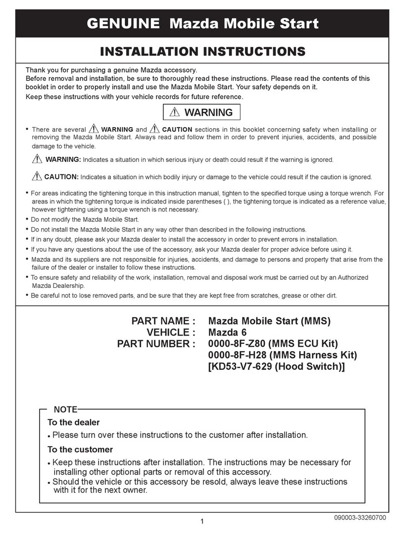
Mazda MAZDA5 2006 User manual

11030658 Rev.A 09/05
PART NUMBER (s):
0000-8F-L05 APPLICABLE MODELS:
2006>MAZDA5
All Models
REMOTE START SYSTEM
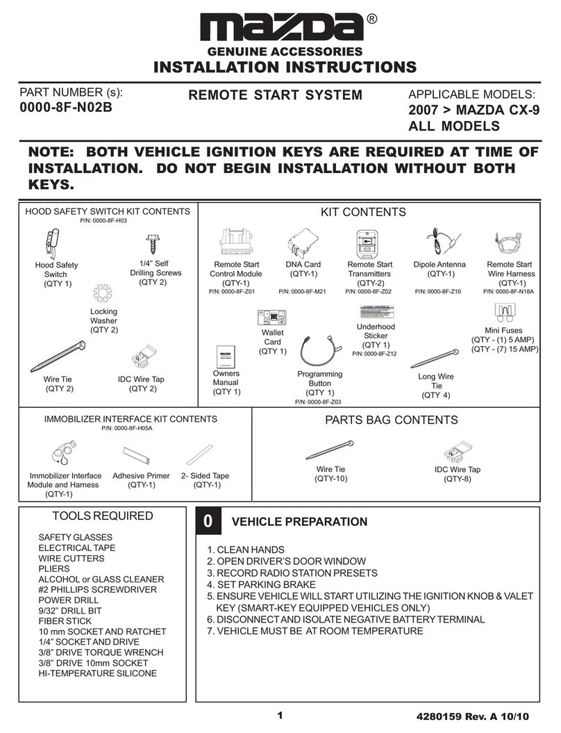
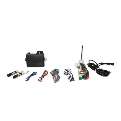
KIT CONTENTS
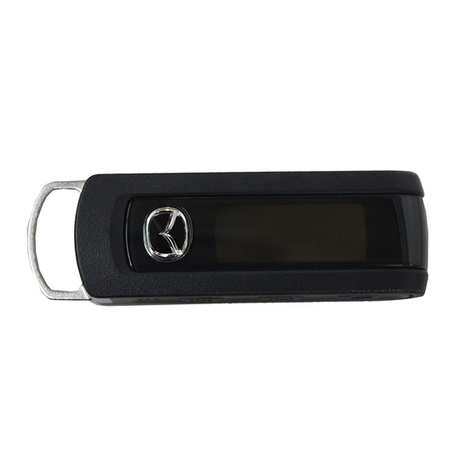
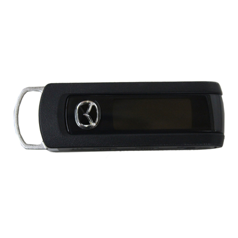
Remote Start DNA Card Remote Start Dipole Antenna Remote Start
Control Module (QTY-1) Transmitters (QTY-1) Wire Harness
(QTY-1) (QTY-2) (QTY-1)
P/N: 0000-8F-Z01 P/N: 0000-8F-F05 P/N:0000-8F-Z02 P/N: 0000-8F-Z10 P/N:0000-8F-L06
1. Disconnect negative battery terminal:
a. Remove relay cover by grasping rear of cover and pulling upwards.
Disengage locking tabs and remove cover. (FIGUREA)
b. Disengage locking tabs and remove cover the battery cover.
c. Disconnect negative battery terminal and isolate.
GENUINE ACCESSORIES
INSTALLATION INSTRUCTIONS
®
Owner's Manual
VehicleRemote Start System
TM
FeaturingPowerCodeTechnology
FortheUltimateinComfort, ConvenienceandSecurity
TM
MAZDA
GENUINEACCESSORIES
WARNING: / AVERTISSEMENT
This vehicle is equipped with a remote controlled engine starter.
To reduce the risk of serious Injury or death, switch engine starter
system into service mode and disconnect the vehicle battery
before performing any service on the vehicle.
Ce véhicule est doté d'un démarreur à distance. Pourréduire les
risques de blessures graves ou mortelles, mettre le démarreur à
distance en mode service et débrancher la batterie du véhicule
avant d'effectuer des travaux d'entretien sur celui-ci.
30
sec.
2sec.
5X
2sec.
Immobilizer Interface Adhesive Primer 2- Sided Tape
Module and Harness (QTY-1) (QTY-1)
(QTY-1)
Tie Wrap
(QTY 2) IDC Wire Tap
(QTY 2)
Hood Safety
Switch
(QTY 1)
Owners
Manual
(QTY 1)
Wallet
Card
(QTY 1)
Underhood
Sticker
(QTY 1)
Long Tie
Wrap
(QTY 4)
Mini Fuses
(QTY - (1) 5 AMP)
(QTY - (7) 15 AMP)
1/4” Self
Drilling Screws
(QTY 2)
PARTS BAG CONTENTS
HOOD SAFETY SWITCH KIT CONTENTS
(P/N: 0000-8F-H03)
Locking
Washer
(QTY 2)
TOOLS REQUIRED
SAFETY GLASSES
ELECTRICAL TAPE
WIRE CUTTERS
PLIERS
ALCOHOL or GLASS CLEANER
PHILLIPS SCREWDRIVER
POWER DRILL
9/32” DRILL BIT
FIBER STICK
10mm SOCKETAND RATCHET
1/4” SOCKETAND DRIVE
3/8” DRIVE TORQUE WRENCH
3/8” DRIVE 10mm SOCKET
0
IMMOBILIZER INTERFACE KIT CONTENTS
(P/N: 0000-8F-H05)
FIGURE A
1VEHICLE PREPARATION
NOTE: BOTH PROGRAMMED
IGNITION KEYS ARE REQUIRED
AT TIME OF INSTALLATION
PRE INSTALLATION
1. CLEAN HANDS
2. OPEN DRIVER’S DOOR WINDOW
3. RECORD RADIO STATIONS
4. SET PARKING BRAKE
5. DISCONNECTAND ISOLATE
NEGATIVE BATTERY TERMINAL
6. VEHICLE MUST BE AT ROOM
TEMPERATURE
Tie Wrap IDC Wire Tap
(QTY-10) (QTY-2)

21030658 Rev.A 09/05
VEHICLE PREPARATION, continued
2. Remove the following components:
a. Using a fiber stick remove the driver’s side scuff plate.
b. Remove the driver’s side kick panel by using a fiber stick
pull the plastic center button of the plastic fastener out to dis-
engage (FIGURE B). Gently pull the kick panel towards the
rear of the vehicle to remove.
c. Unclip the hood release by inserting a fiber stick between the
hood release and the dash panel. There is a center tab the
stick must push down while pulling the hood release towards
the rear of the vehicle.
d. Removeone (1) phillipsscrew behind thehoodreleasehandle.
(FIGURE C)
e. Remove the lower center console kick panels from both
driver and passenger sides by using a fiber stick (FIG-
URE D). Remove (1) phillips screw behind each panel
(FIGURE E).
f. Remove the automatic shifter knob by carefully unscrew-
ing the shifter knob. (FIGURE F)
g. Using a fiber stick, remove the automatic shifter bezel on
the center console and remove the (2) phillips screws
underneath. (FIGUTE G)
h. Using a fiber stick gently unclip the center console panel
an pull towards the rear of the vehicle. Note: Do not re-
move the center console panel.
i. Carefully pull the rubber weather seal away from the door
jamb along the lower dashboard panel. Unclip the lower
dash panel using a fiber stick starting at the bottom and
unplug any connectors attached to the panel.
j. Remove the three (3) phillips head screws from the lower
steering column shroud. (FIGURE H and I)
k. Carefully separate the 2 halves of the steering column
shroud with a fiber stick. Gently unclip the ignition key
light and remove the lower half of the steering column
shroud.
1
FIGUREH FIGUREI
FIGUREC
FIGURE B
FIGURED
FIGUREE
FIGUREG
FIGUREF

31030658 Rev.A 09/05
DIPOLE ANTENNA MOUNTING
1. Remove the following components
a. Remove the driver’s side A-pillar panel being careful not
to damage the retaining clips or the curtain airbag. Care-
fully pull the rubber weather seal away from the door jamb
(FIGURE J) then, starting at the top of the panel, pull the
A-pillar panel toward the inside of the car but DO NOT try
to pull all the way off. There is a white clip at the top which
only releases about an inch then the panel must be slid
off of it by pulling upward. Be very careful not to damage
the head liner or break the white top clip.
b. Push the white top clip back into the A-pillar half way un-
til it rotates freely.
c. Turn the white top clip diagonally and pull straight out of
the A-pillar. (FIGURE K)
d. Slide the removed white clip into position on the A-pillar
panel. (FIGURE L)
2. Clean mounting spot with an alcohol pad prior to mounting.
Mount the dipole antenna to the windshield 210mm to the
right of center on the windshield, directly below the black wind-
shield trim material. (FIGURE M)
3. Run the antenna wire above the headliner to the driver’s A-
pillar, using a fiber stick to secure under the headliner.
Note: Make sure the antenna wire is secure under the head
liner, if necessary remove the sun visor to secure.
4. Route the antenna wire down the A-pillar securing it to the
existing wiring using (3) supplied tie wraps. Do not secure it
directly to the sunroof drain tube or airbag. (FIGURE N)
5. Route the antenna wire behind the left side of the dashboard.
The antenna will be connected to the remote start control
module later.
6. Re-install the driver’s side A-pillar panel and re-install the
weather seal along the A-pillar.
2
FIGUREK
FIGUREJ
FIGUREL
FIGUREN
FIGUREM

41030658 Rev.A 09/05
HOOD SAFETY SWITCH MOUNTING
1. Using (2) supplied 1/4” self drilling screws and (2) supplied lock washers, secure the hood safety switch to
the drivers side of the vehicle’s hood 150mm above the top of the hood mounting bracket and
85mm from the side edge of the hood. (FIGURE O & P)
2. Route the hood safety switch wiring down into the engine compartment along the inside of the hood hinge
and secure using (2) supplied tie wraps. (FIGURE O & Q)
3.Route the hood safety switch wiringalong the cowl panel, tucking under the cowlpanelwhere possible, into
the engine compartment towards the hood release cable grommet. (FIGURE O & R)
4. Disengage hood latch cable and pull through radiator support bracket.
CAUTION: Failure to secure hood latch open with a tie wrap could allow the hood to become
locked without the hood release cable available.
a. Attach a tie wrap to the hood latch mechanism. (FIGURE S)
b. Disconnect the hood latch cable at latch.
c. Free the hood latch cable from (2) retaining clips. (FIGURE T)
3
FIGURES
FIGURET
FIGURER
FIGUREO
FIGUREP
FIGUREQ
85mm
150mm

51030658 Rev.A 09/05
FIGUREV
HOOD SAFETY SWITCH MOUNTING, continued
5. Locate the hood release cable grommet from inside the occupant compartment. (FIGURE U)
6. Pull the hood release cable and grommet approximately 20” into the driver’s side footwell.
(FIGURE V)
7. Using fish wire, pull the hood safety switch wiring through the hood release cable opening:
a. From inside of the vehicle, insert the fish wire through the hood release cable opening.
b. Bend approximately three (3) inches of harness at wire end.
c. Using electrical tape, secure fish wire to harness as shown. (FIGURE W)
d. Pull fish wire and wiring through hood release cable opening. (FIGURE O page 4)
e. Tape the hood safety switch wires against the fish wire and electrical tape in place.
(FIGURE X)
f. Slide the fish wire and wiring through the hood release grommet and pull the excess
wiring through the grommet. (FIGURE Y)
8. Reconnect the hood release cable:
a. Pull the hood release cable back into position. Reattach to hood latch release mechanism and
two (2) retaining clips. (NOTE: Ensure the hood latch cable retaining collar is seated securely).
b. Remove the tie wrap from the hood latch release mechanism.
c. Slide the hood release cable grommet back into position in the vehicle dashwall.
3
FIGUREY
FIGUREU
FIGUREX
FIGUREW

61030658 Rev.A 09/05
REMOTE START CONTROL MODULE PREPARATION
1. Insert the supplied fuses into the remote start control module as shown in below (FIGURE Z).
the fuses fit tight so use a tool handle to seat them in place if necessary.
2. Install DNA card into the remote start control module as shown below. (FIGURE AA)
NOTE: Use care to assure that both rows of the multipin connectors are aligned and seated properly.
3. Plug the supplied wire harness 10-way and 24-way connectors into the remote start control mod-
ule (FIGURE BB). Make sure the harnesses are seated completely. NOTE: The connectors will
only plug into the remote start control module one way.
4. Plug the supplied immobilizer interface 4-way connector into the remote start control module.
(FIGURE BB)
NOTE: TAPE OFF THE WHITE WIRE (IF EQUIPPED) COMING FROM THE 4-WAY
CONNECTOR (THIS WIRE IS NOT USED ON THIS SYSTEM).
4
FIGUREZ
5
15
15
15
15
15
15
5
15
15
15
15
15
15
-+
-+
15
HVAC 1
HVAC 2
MAIN B+
IGNITION
DOME LIGHT PK LIGHTS
DOOR LOCK
S
15
TRUNK RELEASE
To Immobilizer
Interface Module
FIGUREBB
FIGUREAA
REMOTE ENGINE START MODULE AND IMMOBILIZER INTERFACE MOUNTING
5
REMOTE ENGINE STARTMODULE MOUNTING
1. Route the dipole antenna cable (previously installed in step 2)
and plug into the 2-pin connector on the bottom of the remote
start control module.
2. Locate the large dashboard support bracket to the left of the
steering column.
3. Using (3) supplied long tie wraps secure the remote start con-
trol module to the left side of the dashboard support bracket.
Make sure that the remote start control module is not mounted
to far down on the bracket, this will eliminate problems with
dashboard reassembly. (FIGURE CC)
IMMOBILIZER INTERFACE MODULE MOUNTING
1. Locate the Large dashboard support bracket to the left of the
steering column.
2. Using (1) supplied long tie wrap, secure the immobilizer inter-
face to the dashboard bracket. (FIGURE DD)
Tie Wraps
FIGURECC
Tie Wraps
FIGUREDD

71030658 Rev.A 09/05
GROUND CONNECTION
1. Locate the 10mm factory bolt located in the driver’s kick panel area.
(FIGURE EE)
2. Using a 10mm ratchet remove the 10mm lug bolt.
3. Re-secure the factory ground ringlet and remote start harness BLACK/
ORANGE ground wire with ringlet and tighten with a 10mm ratchet.
(FIGURE FF)
NOTE: USING A3/8” DRIVE TORQUE WRENCH MAKE SURE
THAT THE 10mm GROUND LUG BOLT IS SECURELY TIGHT-
EN 78-121 INCH/POUNDS.
7
HOOD SAFETY SWITCH MOUNTING WIRE CONNECTIONS
1. Locate the BLACK/ORANGE and GRAY/RED wire from the remote start system harness.
2.Locate the wires listed below. Ifthe hood safety switch wirehasa ground ringlet terminal or astrippedend
on either wire then cut the ends of the wires so they are blunt.
3. Using the (2) supplied IDC wire taps (in hood safety switch parts bag), connect the switch wires listed
below together and crimp the IDC wire tap in place using pliers, assure that a complete and secure
connection is made.
6
HOOD SAFETY SWITCH WIRE REMOTE START HARNESS WIRE
Dk. GRAY GRAY/RED
Dk. GRAY BLACK/ORANGE
NOTE: Switch is not polarity sensitive.
FIGUREEE
FIGUREFF

81030658 Rev.A 09/05
SYSTEM LAYOUT

91030658 Rev.A 09/05
IMMOBILIZER INTERFACE RIBBON CABLE MOUNTING
8
1. Route the immobilizer interface (previously installed) ribbon cable
to the ignition switch, making sure to keep it away from any moving
parts.
2. Following the instructions on the supplied ampule of adhesive primer,
apply a thin coating to the entire transceiver antenna ring (black plastic
ring around key switch, FIGURE GG) and to the ribbon cable.
3. Remove the backing from one side of the supplied 2-way tape and apply
tape around the transceiver antenna ring (black plastic behind ig-
nition switch) keeping the tape off of the rounded part of the igni-
tion switch face and trimming excess 2-way tape if necessary.
4. Remove the remaining backing on the 2-way tape and position the
ribbon cable around the transceiver antenna ring, with the striped
side facing the ignition key opening. (FIGURE HH & II)
5. Using a supplied tie wrap, secure the antenna coil. .
(FIGURE HH & II)
FIGUREGG
FIGUREHH
FIGUREII
WIRE HARNESS CONNECTIONS- STEERING COLUMN
9
IGNITION SWITCH CONNECTOR (C-456 CONNECTOR)
2. Route the remote start ignition harness with 8-way male and fe-
male ignition connectors and 12-way male and female multifunction
switch connector, transponder interface wiring and ribbon cable
acrossand up the left of the steeringcolumn harness, do not secure
harness at this time.
3. Locate the 8-way WHITE and GREY ignition connector, on the left
side of the steering column.
4. Release the GREY secondary latch and remove the 8-way WHITE
ignition connector by pulling upwards.
5. Plug the remote start harness 8-way WHITE female connector into
the factory ignition switch, replace the GREY secondary latch and
secure harness in place. (FIGURE JJ)
6. Connect the remote start harness 8-way male connector into the
factory ignition harness, and replace the GREY secondary latch.
(FIGURE KK)
FIGUREJJ
FIGUREKK

10 1030658 Rev.A 09/05
WIRE HARNESS CONNECTIONS- STEERING COLUMN
9
MULTIFUNCTION SWITCH CONNECTOR (C-459 CONNECTOR)
1. Locate the 12-way WHITE multifunction switch connector on the left
side of the steering column (plugged into the turn signal assembly).
2. Remove the 12-way connector from the multifunction switch.
3. Plug the 12-way female remote start harness connector into the
multifunction switch. (FIGURE LL)
4. Plug the previously removed vehicle 12-way female connector into
the remote start harness 12-way male connector. (FIGURE LL)
5. Using (2) supplied tie wraps, secure the 12 way multifunction switch
harness to the factory wiring on the left side of the steering column.
(FIGURE MM)
HORN CONNECTION (CLOCKSPRING C-437 CONNECTOR)
1. Locate the 12-way YELLOW C-437 clockspring connector at
the base of the steering wheell.
2. Using a razor knife carefully cut back 1”-2” of the plastic shield-
ing to expose the wiring (BE EXTREMELY CAREFUL NOT TO
DAMAGE ANY OF THE WIRES).
3. Using the (1) supplied IDC wire tap, connect the wire listed be-
low and crimp the IDC wire tap in place using pliers, assure
that a complete and secure connection is made. Refer to FIG-
URE NN & OO for proper connector and pin location.
4. Using (2) supplied tie wraps secure the remote start wiring and
immobilizer interface wiring to the vehicle’s factory ignition wir-
ing. (FIGURE PP)
NOTE: IT IS EXTREMELY IMPORTANT THAT THE WIR-
ING IS SECURED IN A MANNER THAT WILL ALLOW
THE TILT/TELESCOPING STEERING WHEEL TO MOVE
FREELY AND STILL ALLOW FOR REASSEMBLY OF THE
STEERING COLUMN SHROUD. CHECK FUNCTIONAL-
ITY OF THE TILT TELESCOPING STEERING WHEEL
PRIOR TO REASSEMBLY.
FIGUREMM
FIGURELL
x
VIEW FROM WIRE END
VIOLET/WHITE PIN
LOCATION INDICATED BY X
FIGURENN
FIGUREOO
FIGUREPP
VEHICLE’S HORN WIRE REMOTE START HARNESS WIRE
VIOLET/WHITE VIOLET/WHITE

11 1030658 Rev.A 09/05
WIRE HARNESS CONNECTIONS- BRAKE SAFETY
1. Locate the wire harness running along the firewall on the left side
of the steering column near the hood release cable (directly in
front of the module mounting location). (FIGURE QQ)
2. Locate the wire GREEN/YELLOW brake switch wire. NOTE: There
will be only (1) GREEN/YELLOW wire in this harness.
3. Place (1) supplied IDC wire tap on to the vehicle wire (using the
side of the IDC wire tap that is open on both ends).
4. Insert the wire from the remote start harness into the other side of
the IDC wire tap and crimp in place with pliers.
10
REMOTE START HARNESS VEHICLE WIRE
GREEN/YELLOW GREEN/YELLOW
FIGUREQQ
EMERGENCY OVERRIDE/PROGRAMMING BUTTON MOUNTING
1. Locate the previously removed driver’s side kick panel cover.
2. Drill a 9/32” hole at the top of the panel, approximately 76mm down and 102mm from the far edge.
3. Route the emergency override/programming button from the remote start harness down to the kick
panel.
4.Mount the emergency override/programming buttoninthe drilled hole from behindandscrew the mounting
cap in place. (FIGURE RR)
NOTE: DISCARD THE LOCK WASHER FROM THE EMERGENCY OVERRIDE/PROGRAM-
MING BUTTON, IT IS NOT USED ON THIS MODEL.
5. Re-install driver’s side kick panel cover
11
FIGURERR
76mm
102mm

12 1030658 Rev.A 09/05
RE-ASSEMBLY
1. Re-install the following components:
a. Plug the ignition key light back into the lower steering
column shroud, carefully snap the steering column shroud
halves together and re-install the (3) phillips screws (all
three are the same type). Verify operation of the tilt/tele-
scoping steering wheel. (FIGURE SS & TT)
b. Carefully pull the weather seal away from the door jamb
along the driver’s side of the dashboard. Re-install the
driver’s lower dashboard panel and re-secure the weather
seal.
c. Secure the center console panel and re-install the (3)
phillips screws around the shifter assembly and (1)
phillips screw on each side of the lower center console
panel. (FIGURE UU & VV)
d. Re-install the automatic shifter bezel and screw the shifter
knob on to the shift lever making sure that the shifter knob
is tight and lined up straight. (FIGURE WW)
e. Re-install the lower center console kick panels on both
driver and passenger sides. (FIGURE XX)
f. Re-install (1) phillips screw on the lower left side of the
driver’s dashboard and re-install the hood release handle.
(FIGURE YY)
12
FIGURETT
FIGUREYY
FIGUREXX
FIGUREVV
FIGUREUU
FIGUREWW
FIGURESS

13 1030658 Rev.A 09/05
SYSTEM POWER-UP
1. Verify that all connections are secure as per installation instructions.
2. Turn the ignition key to the RUN position.
3. Reconnect the negative battery terminal.
4. Turn the ignition key to the OFF position.
5. VERY IMPORTANT - USING THE IGNITION KEY, TURN THE IGNITION TO THE ON POSITION THEN
CRANK ENGINE UNTIL IT STARTS ONE TIME THEN SHUT THE VEHICLE OFF.
13
IMMOBILIZER INTERFACE PROGRAMMING
NOTE: IF YOU DID NOT START THE CAR WITH THE IGNITION KEY AS INSTRUCTED TO IN SECTION 13 STEP 5
THEN THE VEHICLE WILL NOTATTEMPT TO START, INSTEAD YOU WILLGET THREE ADDITIONALBEEPS FROM
THE HORN. THE VEHICLE HAS TO BE STARTED AT LEAST ONCE WITH THE KEY FOR THE REMOTE ENGINE
START FUNCTION TO OPERATE.
1. Transponder interface programming:
NOTE: Two programmed ignition keys are required for this step and hood must be closed.
a. Sitting in the driver seat, be prepared to press the brake pedal to shut down the remote starter
system.
b. Using the first key, turn the ignition on, wait for the THEFT light to turn off, then turn the ignition off and
remove key from the ignition switch.
c. Using the second key within 5 seconds, turn the ignition on, wait for the THEFT light to turn off, then
turn the ignition off and remove key from the ignition switch.
d. Activate the remote start function by pressing the START button (2) times within 5 seconds.
The system should flash the parking lights and chirp the horn one time, pause for four seconds then
start the engine.
e.After the engine is started. Press the brake pedal to shutdown the engine. The Immobilizer interface is
now programmed.
f. Attach new Remote Engine Start transmitters to the retractable keys.
15
UNDERHOOD WARNING LABEL MOUNTING
14
1.Open the engine hood and find asuitablemounting location intheengine compartmentthatwill be in plain
sight when the hood is open (on the radiator cowl).
2. Using an alcohol pad, clean the mounting surface thoroughly.
3. Remove the backing on the underhood sticker and mount in place.
4. Close hood.

14 1030658 Rev.A 09/05
FUNCTION TEST
16
CarFind
1. Press and hold START button - Horn should beep five times and parking lights should flash five times.
RemoteEngineStartFunctions
1. REMOTE ENGINE START; Make sure the key is removed from the ignition switch and the engine hood is
closed. Press the START button twice within 3 seconds - The parking lights should flash one time, the horn
shouldbeeponcethenthevehicle should crank and start. Once started the parking lights will turn on and stay
on signifying the vehicle is started.
2. RUNNING WITH IGNITION KEY - While the vehicle is running on the remote engine start, confirm that all
functionoperateproperlyontheFACTORYtransmitter/retractablekey.OnceFACTORYtransmitterfunctionality
isconfirmed,pressthe UNLOCK button on FACTORYtransmitterandenterthevehicle,insertthe ignition key
andturn the ignition totherun position, press thebrakepedal-At thistimethevehicle should be runningonthe
ignitionkey and theremoteengine startwasshutdown whenthebrakepedal waspressed.Turn off theignition
switchandthe vehicle should shut off.
3.BRAKEPEDAL SAFETY - Restart the vehicle using the remoteenginestart,enterthevehicle,press the brake
pedal-The vehicle should shut off.
4. KEY-IN-SENSE - Insert the ignition key into the ignition switch but keep in off position, activate the remote
engine start function - the vehicle should flash the lights as if it is going to start but then the horn should beep
twiceandtheremoteenginestarterdoesnotattempt to start the vehicle since it senses the key in the ignition.
5. HOOD SAFETY SWITCH - Open the engine hood and activate the remote engine start function - The horn
should beep two additional times signifying that hood safety switch is tripped and the vehicle will not start.
(referencesection18ifadjustment is needed)
FUNCTIONALTESTINGISNOWCOMPLETE.
SYSTEM PROGRAMMING
17
NOTE: THE FOLLOWING STEPSARE ONLY NECESSARY IFYOU NEED TO PROGRAMADDITIONAL
TRANSMITTERS.
1. Transmitter Programming
NOTE: The transmitters shipped with the remote start system are pre-programmed to the DNA
card, and do not need to be reprogrammed.
a. Turn the ignition key to the ON or RUN position.
b. Press and hold the programming button.
After 10 seconds the horn will beep 3 times, indicating that the system is now in transmitter learn
mode.
c. Release the programming button.
d. If programming transmitters at this time, press the START button once on each transmitter to be
programmed.
The horn will beep 1 time to indicate that the transmitter has been learned.
NOTE: Up to a total of 8 transmitter can be programmed at this time.

15 1030658 Rev.A 09/05
SERVICE PART NUMBER LIST
19
Part Number Description
0000-8F-H03 Hood Safety Switch Kit
0000-8F-Z01 Remote Start Control Module Service Part
0000-8F-L06 Mazda5 Remote Start Wire Harness Service Part
0000-8F-H05 Mazda5 Immobilizer Interface Service Part
0000-8F-F05 Mazda5 DNA Card Software Service Part
0000-8F-Z02 Mazda5 1-Button Remote Start Transmitter Service Part
0000-8F-Z10 Dipole Antenna
PowerCode®, IT-s®, Real Panic Sound® and Progressive Find® are registered trademarks of Code Systems, Inc.
The hood safety will need to be adjusted to shutdown the vehicle when the hood is raised to the full upright position
1.Raiseandpropthevehicle’shood.
2.Thehoodswitch cylinder should be bend away from the hood to approximately 15 degreesabove parallelwiththe
ground. (FIGURE ZZ)
3.After the adjustment has been made verify that remote start system does not engage when the vehicle’s hood is
open.
4. If the remote start system engages with the hood in the full upright position, the switch will need to be bent closer to
the hood.
18
NOTE: IT IS VERY IMPORTANT TO VERIFY THAT THE HOOD
SAFETY SWITCH PREVENTS THE REMOTE ENGINE START
SYSTEM FROM ENGAGING WHEN THE VEHICLE’S HOOD IS
IN THE FULL UPRIGHT POSITION FIGUREZZ
HOOD SAFETY SWITCH ADJUSTMENT

16 1030658 Rev.A 09/05
CIRCUIT LAYOUT PAGE 1 of 1
1
1
2
2
3
3
4
4
5
5
6
6
7
7
8
8
9
9
10
10
10-WAY PCT CAR START CONNECTOR
ACC
ACC
12
12
MAIN HARNESS
MAIN HARNESS
--
--
--
--
--
--
--
--
--
--
20
20
20
20
20
20
--
--
--
--
--
--
9
9
11
11
12
12
10
10
6
6
7
7
8
8
3
3
4
4
5
5
21
21
23
23
24
24
22
22
20
20
19
19
15
15
16
16
17
17
18
18
VIEW FROM TERMINAL END
--
--
--
--
1
1
2
2
P2
P2
--
--
HD1
HD1
C437-B
C437-B
--
--
--
--
--
--
P1
P1
13
13
14
14
--
--
20
20
--
--
--
--
--
--
BR
BR
GY/RD
GY/RD
--
--
VT/WT
VT/WT
--
--
--
--
--
--
--
--
BR
BR
--
--
--
--
ST-2
ST-2
--
--
--
--
--
--
--
--
1E, 1E-A, 1E-B
1E, 1E-A, 1E-B
B1
B1
ST-1
ST-1
IG1
IG1
459A
459A
--
--
--
--
14
14
--
--
--
--
--
--
12
12
16
16
14
14
12
12
22
22
--
--
--
--
BL/RD
BL/RD
--
--
--
--
--
--
--
--
BL
BL
BK
BK
BK/OR
BK/OR
BK/BL
BK/BL
BN/RD
BN/RD
--
--
VIEW FROM TERMINAL END
1
1
6
6
7
7
12
12
1/4" RING TERMINAL
1/4" RING TERMINAL
459A,459A-A,459A-B
459A,459A-A,459A-B
BN/RD
BN/RD
459D
459D
459B
459B
459F
459F
459H
459H
459J
459J
459L
459L
459A-B
459A-B
GY
GY
YL
YL
22
22
22
22
BL/YL
BL/YL
PK
PK
WT/BL
WT/BL
VT
VT
22
22
22
22
22
22
22
22
22
22
459K
459K
459C
459C
459E
459E
459G
459G
459I
459I
BK
BK
LT GN
LT GN
BK/OR
BK/OR
WT/RD
WT/RD
GN
GN
22
22
22
22
22
22
22
22
22
22
B1,B1-A,B1-B
B1,B1-A,B1-B
KIS,KIS-A,KIS-B
KIS,KIS-A,KIS-B
IG1,IG1-A,IG1-B,IG1-C
IG2,IG2-A,IG2-B
IG2,IG2-A,IG2-B
BN/RD
BN/RD
459D
459D
459B
459B
459F
459F
459H
459H
459J
459J
459L
459L
459A-A
459A-A
GY
GY
YL
YL
22
22
22
22
BL/YL
BL/YL
PK
PK
WT/BL
WT/BL
VT
VT
22
22
22
22
22
22
22
22
22
22
459K
459K
459C
459C
459E
459E
459G
459G
459I
459I
BK
BK
LT GN
LT GN
BK/OR
BK/OR
WT/RD
WT/RD
GN
GN
22
22
22
22
22
22
22
22
22
22
6
6
1
1
12
12
7
7
ACC,ACC-A,ACC-B
ACC,ACC-A,ACC-B
--
--
B2, B2-A, B2-B, B2-C
1
1
1
1
20GY/RD
20GY/RD
HD1
HD1
20BK/OR
20BK/OR
1E-A
1E-A
20GN/YL
20GN/YL
BRK
BRK
16BK/OR
16BK/OR
1E-B
1E-B
1
1
1
1
20VT/WT
20VT/WT
C437-B
C437-B
1. PLACEMENT OF SPLICES NOT CRITICAL
2.
2.
NOTE:
NOTE:
TAPE WRAPPED OR SLEEVE COVERED WIRE
UNWRAPPED WIRE
UNWRAPPED WIRE
= DIAPER WRAP
= DIAPER WRAP
4.
4.
= SPOT TAPE, SPACED EVENLY ALONG RUN
5.
5.
6. WRAP WITH ALUMINUM SHIELDING TAPE THEN COVER WITH TAPE WRAP OR DRY VINYL TAPE.
3.
3.
TACH SENSE INPUT
TACH SENSE INPUT
BRAKE INPUT
BRAKE INPUT
ACTIVE OUTPUT
ACTIVE OUTPUT
KEY-IN-SENSE INPUT
KEY-IN-SENSE INPUT
HVAC 1 OUTPUT
HVAC 1 OUTPUT
IGNITION 2 OUTPUT
IGNITION 2 OUTPUT
HVAC 2 FEED
HVAC 2 FEED
CIRCUIT DESCRIPTION
CIRCUIT DESCRIPTION
CAV
CAV
CIRCUIT NAME
CIRCUIT NAME
B2
8
8
9
9
10
10
4
4
6
6
5
5
7
7
2
2
3
3
HVAC 2 OUTPUT
HVAC 2 OUTPUT
NOT USED
NOT USED
HVAC 1 FEED
HVAC 1 FEED
COLOR
COLOR
GA
GA
WT/BL
WT/BL
20
20
--
--
--
--
--
--
BL
BL
12
12
VT
VT
GN/YL
GN/YL
--
--
--
--
BK/RD
BK/RD
BK/YL
BK/YL
BK/YL
BK/YL
12
12
12
12
16
16
B2-A
B2-A
IG2
IG2
IG1-C
IG1-C
--
--
BRK
BRK
KIS
KIS
--
--
--
--
--
--
20
20
CIRCUIT NAME
CIRCUIT NAME
13
13
23
23
24
24
18
18
20
20
19
19
22
22
21
21
16
16
14
14
15
15
17
17
8
8
9
9
12
12
10
10
11
11
4
4
5
5
6
6
7
7
3
3
2
2
CAV
CAV
TRNK REL/DRV DR UNLK REL OUTPUT
N/A - SIREN OUTPUT
N/A - SIREN OUTPUT
DOOR UNLOCK OUTPUT
DOOR UNLOCK OUTPUT
PROGRAMMING/OVERIDE BUTTON
DRVR'S UNLOCK OUTPUT/TRUNK OUT
PROGRAMMING/OVERIDE BUTTON
HOOD OPEN SWITCH INPUT
HORN RELAY OUTPUT
HORN RELAY OUTPUT
DOOR AJAR SWITCH INPUT
N/A - LED
N/A - LED
N/A - LED
N/A - LED
N/A - SIREN FEED
N/A - SIREN FEED
GA
GA
DISARM INPUT
DISARM INPUT
UNLOCK SWITCH SENSE INPUT
IGNITION 1 INPUT/OUTPUT
DOOR TRIGGER PULL-UP
STARTER INTERRUPT (MOTOR SIDE)
DOME LIGHT OUTPUT
DOME LIGHT OUTPUT
PARKING LIGHT OUTPUT
CIRCUIT DESCRIPTION
CIRCUIT DESCRIPTION
STARTER INTERRUPT (KEY SIDE)
DOOR LOCK OUTPUT
DOOR LOCK OUTPUT
ARM INPUT
ARM INPUT
BATTERY
BATTERY
GROUND
GROUND
COLOR
COLOR
PARKING LIGHT (-) OUTPUT
6
6
EXT-2
EXT-2
HEADLIGHT (-) INPUT
HEADLIGHT (-) INPUT
EXT-3
EXT-3
LEFT TURN SIGNAL (-) INPUT
EXT-1
EXT-1
FRONT FOG LAMP (-) INPUT
11
11
12
12
7
7
9
9
8
8
10
10
AUTOLAMP (-) INPUT
AUTOLAMP (-) INPUT
GROUND
GROUND
HIGH BEAM (-) INPUT
HIGH BEAM (-) INPUT
REAR FOG LAMP (-) INPUT
RIGHT TURN SIGNAL (-) INPUT
CIRCUIT DESCRIPTION
CIRCUIT DESCRIPTION
CIR NAME
CIR NAME
2
2
4
4
3
3
5
5
CAV
CAV
COLOR
COLOR
GA
GA
KIS-A
KIS-A
ST-1
ST-1
CIR NAME
CIR NAME
C456 IGNITION SWITCH CONNECTOR (SWITCH SIDE)
TERMINAL END VIEW
TERMINAL END VIEW
5
5
1
1
4
4
8
8
3
3
4
4
8
8
5
5
6
6
4
4
5
5
1
1
CAV NUM
CAV NUM
1
1
2
2
TERMINAL END VIEW
TERMINAL END VIEW
20
20
12
12
12
12
12
12
IG2-A
IG2-A
B2-B
B2-B
GA
GA
20
20
12
12
B1-A
B1-A
IG1-A
IG1-A
COLOR
COLOR
STARTER
STARTER
12V+ BATTERY
12V+ BATTERY
KIS +12V FEED
KIS +12V FEED
KEY IN SENSE
KEY IN SENSE
PRIME IGNITION
PRIME IGNITION
FUNCTION
FUNCTION
12V+ BATTERY
12V+ BATTERY
BK
BK
BL/RD
BL/RD
WT/BL
WT/BL
BL
BL
BK/YL
BK/YL
VT
VT
ACC-A
ACC-A
7
7
8
8
14
14
12
12
BKIS
BKIS
2ND IGNITION
2ND IGNITION
ACCESSORY
ACCESSORY
BK/RD
BK/RD
BK/BL
BK/BL
KIS-B
KIS-B
ST-2
ST-2
CIR NAME
CIR NAME
C456 IGNITION SWITCH CONNECTOR (MOTOR SIDE)
3
3
5
5
6
6
4
4
CAV NUM
CAV NUM
1
1
2
2
20
20
12
12
12
12
12
12
IG2-B
IG2-B
B2-C
B2-C
GA
GA
20
20
12
12
B1-B
B1-B
IG1-B
IG1-B
COLOR
COLOR
STARTER
STARTER
12V+ BATTERY
12V+ BATTERY
KIS +12V FEED
KIS +12V FEED
KEY IN SENSE
KEY IN SENSE
PRIME IGNITION
PRIME IGNITION
FUNCTION
FUNCTION
12V+ BATTERY
12V+ BATTERY
BK
BK
BL/RD
BL/RD
WT/BL
WT/BL
BL
BL
BK/YL
BK/YL
VT
VT
ACC-B
ACC-B
7
7
8
8
14
14
12
12
BKIS
BKIS
2ND IGNITION
2ND IGNITION
ACCESSORY
ACCESSORY
BK/RD
BK/RD
BL/RD
BL/RD
TERMINAL END VIEW
TERMINAL END VIEW
TERMINAL END VIEW
TERMINAL END VIEW

5
15
15
15
15
15
15
5
15
15
15
15
15
15
-
+
-
+
15
HVAC 1
HVAC 2
MAIN B+
IGNITION
DOME LIGHT PK LIGHTS
DOOR LOCKS
15
TRUNK RELEASE
ATTENTION:
Installation Instruction change for P/N 0000-8F-L05B
The Fuse placement position changed for REMOTE START SYSTEMS
on all Mazda 5 vehicles.
The Dome Light Fuse must be placed in the positive position in order to
disarm the Factory perimeter alarm during the remote start sequence.
See drawing below.
Rev. A 12/07

11032538 Rev. B 1/08
PART NUMBER (s):
0000-8F-L05B APPLICABLE MODELS:
2006-08 MAZDA 5
TACHOMETER CONNECTION
SUPPLEMENT
GENUINE ACCESSORIES
INSTALLATION INSTRUCTIONS ADDENDUM
®
TACHOMETER WIRE REMOTE START HARNESS WIRE
BLACK/WHITE WHITE
TACH WIRE CONNECTION TO VEHICLE
1. Locate the WHITE 56” Tach wire in the remote start wire harness.
This wire is covered with black shrink wrap for protection against
moisture and heat when routing in the engine compartment.
2. Route the Tach wire to the dashwall following the existing remote
start wiring and fish through the dashwall grommet utilizing the
same location as the hood switch safety wiring. Pull the extra
slack from the Tach wire into the engine compartment and route to
the PowerTrain Control Module.
NOTE: PCM is located to the left of the vehicle’s battery.
(FIGURE A)
3. Locate the BLACK/WHITE wire (Negative side of Ignition Coil) in
pin #2BE (2006-2007 models) or pin #2G (2008 models) of the
60-pin front connector at the PCM. Refer to FIGURE A & B for
proper connector and pin location.
4. Using a razor knife, carefully cut back 1”-2” of the electrical tape to
expose the wiring. ( CAUTION: BE EXTREMELY CAREFUL
NOT TO DAMAGE ANY OF THE WIRES.)
5. Using (1) supplied IDC wire tap, connect the wires listed below
and crimp the IDC wire tap in place using pliers. Ensure that a
complete and secure connection is made. Apply silicone to both
ends of the IDC wire tap to seal the connections from potential
moisture.
WIRE HARNESS CONNECTION
1
FIGUREA
PCMFront
Connector
FIGUREB VIEWFROMHARNESS
L/W
Y/R
WB
Y/G
R/B
B BR/Y
L/O
LG/B
W/G
Y
B/W
BR/WG
W/L
G/R
B
Y/R
GR/GGY
R/L
L/B
B/L
B/W
B/Y
B/R
2AC
2AN
2Y
2AH 2V
2AM
2AL
2AE 2W
2F
2X 2D
2J
2AF
2B
2U
2AD
2AB
2I
2AI 2AA
2AK
2C
2M2Q
2K 2G
2R 2N
2O2S
2E 2A
2Z
2T 2P2AJ 2H2L
2AG
2AV
2AS 2AO
2AR
2AQ
2AP
2AU
2AT
2AZ
2AW
2AY
2AX
2BD
2BA
2BC
2BB
2BH
2BE
2BG
2BF
B
W/GBR
W
O/L
BR/R B/G
L
G/Y P L/Y
BR
Pin 2BE
(2006-2007)
Pin2G
(2008)
!

21032538 Rev. B 1/08
SYSTEM POWER-UP
2
1. Verify that all connections are secure as per installation instructions.
2. Turn the ignition key to the RUN position.
3. Reconnect the negative battery terminal.
4. Turn the ignition key to the OFF position.
TACHOMETER PROGRAMMING
3
1. Tachometer Programming - Make sure engine hood is closed!
a. Turn the ignition key to the ON or RUN position.
b. Press and hold the brake pedal and programming button. After 10 seconds the horn will beep
3 times.
Continue holding the brake pedal and programming button for another 10 seconds.
c. Release & press and release the programming button a second time. The horn will beep 4
times.
d. Release the brake pedal.
e. Press and release the brake pedal. The horn will beep 1 time indicating option 1.
f. Press and release the brake pedal. The horn will beep 2 times indicating option 2.
g. Press and release the brake pedal. The horn will beep 3 times indicating option 3.
h. Press the START button on the transmitter one time.
i. Press and release the programming button a third time. The horn will beep 5 times.
j. Press and release the brake pedal. The horn will beep 1 time indicating option 1.
k. Press and hold the brake pedal. The horn will beep 2 times indicating option 2
(Tachometer Learn Mode).
l. Start the vehicle with the ignition key and let engine warm up to a normal idle rate. (Less than
1000 RPMs)
The horn will beep 1 time every 3 seconds indicating the system is monitoring the idle rate.
Continue holding the brake pedal while the engine is running and warming up.
m. Once the vehicle’s engine has warmed up, press and release the programming button.
The horn will beep 4 times, indicating that the system has learned the current idle rate.
n. Release the brake pedal.
o. Turn the ignition key to the OFF position.
p. Proceed to Step 15 of the Mazda 5 Installation Instruction Manual to continue programming.

31032538 Rev. B 1/08
4TROUBLESHOOTING GUIDE
1. Horn honks 4 times & vehicle does not start - No tachometer signal learned to DNA card.
a. Ensure good connection and correct vehicle wire at PCM (See Step 1).
b.Re-programtachometersignal (See Step 3).
2. Starter cranks too long during Remote Start.
a.Re-program tachometersignal (See Step 3) and allowengine to warm up to anormal idle rate (Less than 1000
RPMs).
3. Ignition turns on, then horn honks 2 times & vehicle does not start - Key-in-sense circuit activated.
a.Removeignitionkeyfromignitioncylinder.
4. Horn honks 2 times & vehicle does not start - Safety input activated or Service/Valet Mode engaged.
a. Ensure hood is closed and hood switch is adjusted properly (See Step 18 of Installation Instructions).
b. Ensure brake pedal is not depressed.
c.Ensuregoodconnection and correct vehicle brake wire (See Step 10ofInstallationInstructions).
d.DisengageService/ValetMode(SeePage4 of Owner’sManual).
5. Ignition turns on, Theft indicator is flashing & vehicle does not start - Immobilizer Interface issue.
a. Ensure 4-way connector is engaged into the remote start control module properly (See Step 4 of Installation
Instructions).
b.EnsureImmobilizerInterfaceRibbonCableisinstalledproperly (SeeStep 8of InstallationInstructions).
c.Double-wraptheImmobilizerInterfaceRibbon Cable to create two loops around the immobilizer antenna coil.
d.Re-programimmobilizerinterface(See Step15of Installation Instructions).
6. Engine starts and stalls up to 5 times without the engine staying running - No tachometer signal learned to DNA card.
a. Ensure good connection and correct vehicle wire at PCM (See Step 1).
b.Re-programtachometersignal (See Step 3).
Other manuals for MAZDA5 2006
1
Table of contents
Other Mazda Remote Starter manuals

Mazda
Mazda GENUINE C930 V7 620 User manual

Mazda
Mazda Remote Start System User manual

Mazda
Mazda 0000-8F-H28 User manual

Mazda
Mazda BCKA V7 620 User manual
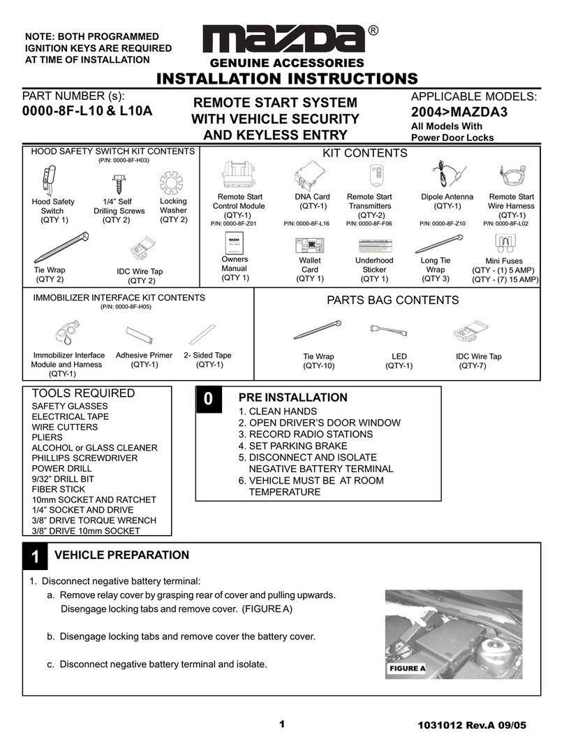
Mazda
Mazda GENUINE C930 V7 620 Programming manual

Mazda
Mazda C960 V7 620 User manual

Mazda
Mazda PZ170-04021 User manual

Mazda
Mazda GENUINE C930 V7 620 User manual

Mazda
Mazda 3 2004 User manual
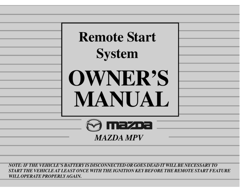
Mazda
Mazda Remote Start System MPV User manual