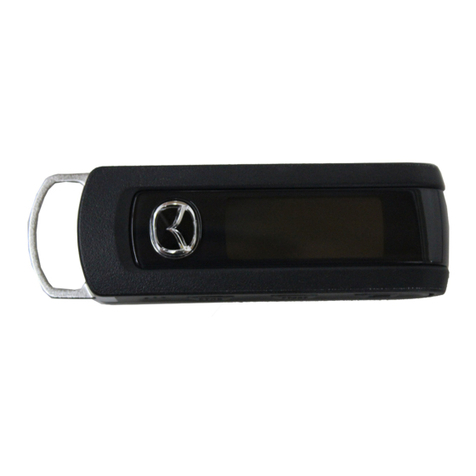
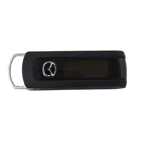
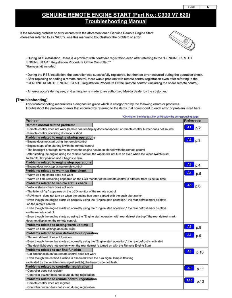
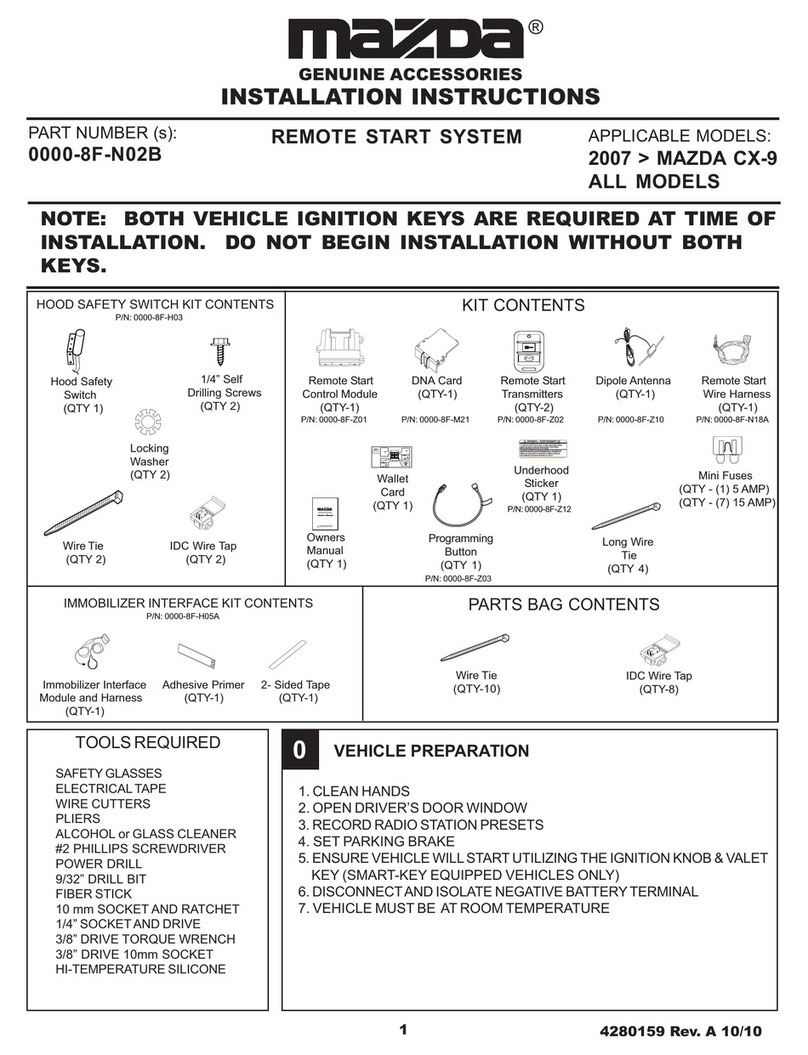
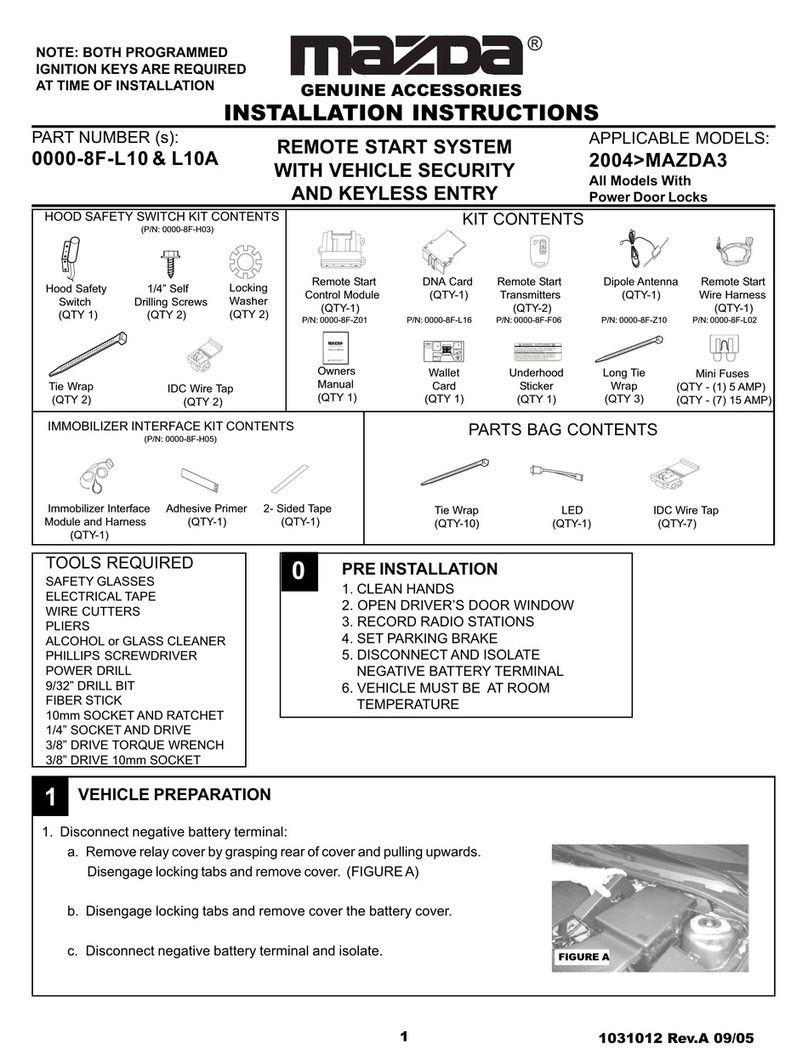
Mazda 6 2006 User manual

11030832 Rev.A 10/05
PARTNUMBER(s):
0000-8F-H13 APPLICABLE MODELS:
2006>MAZDA6
ALL MODELS
REMOTE START SYSTEM
VEHICLEPREPARATION
1. Remove the driver’s side lower dash panel.
a. Unclip the hood release by inserting a fiber stick between the
hood release and the dash panel. There is a center tab the
stick must push down while pulling hood release towards the
rear of the vehicle.
b. Remove (2) 8mm bolts behind the hood release cable.
(FIGURE A)
c. Unsnap lower dash panel using a fiber stick starting at the
bottom.
d. Unplug the trunk release connector after removing the lower
dash panel.
2. Remove the driver’s side lower dash kneeblocker bracket (4) phil-
lips head screws and remove bracket. (FIGURE B)
GENUINE ACCESSORIES
INSTALLATION INSTRUCTIONS
®
BOTH PROGRAMMED IGNITION
KEYSAREREQUIREDAT TIME
OF INSTALLATION
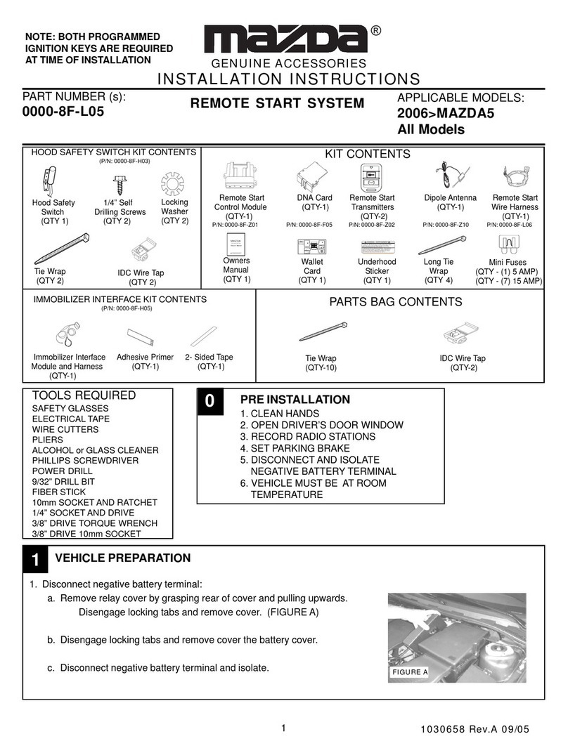
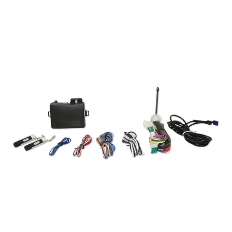
KITCONTENTS
Remote Start DNA Card Remote Start Dipole Antenna Remote Start
Control Module (QTY-1) Transmitters (QTY-1) Wire Harness
(QTY-1) (QTY-2) (QTY-1)
P/N: 0000-8F-Z01 P/N: 0000-8F-H16 P/N: 0000-8F-Z02 P/N: 0000-8F-Z10 P/N: 0000-8F-H17
Owner's Manual
VehicleRemote Start System
TM
FeaturingPowerCodeTechnology
FortheUltimateinComfort, ConvenienceandSecurity
TM
MAZDA
GENUINEACCESSORIES
WARNING: / AVERTISSEMENT
This vehicle is equipped with a remote controlled engine starter.
To reduce the risk of serious Injury or death, switch engine starter
system into service mode and disconnect the vehicle battery
before performing any service on the vehicle.
Ce véhicule est doté d'un démarreur à distance. Pour réduire les
risques de blessures graves ou mortelles, mettre le démarreur à
distance en mode service et débrancher la batterie du véhicule
avant d'effectuer des travaux d'entretien sur celui-ci.
30
sec.
2sec.
5X
2sec.
Immobilizer Interface Adhesive Primer 2- Sided Tape
Module and Harness (QTY-1) (QTY-1)
(QTY-1)
Tie Wrap
(QTY 2) IDCWireTap
(QTY 2)
Hood Safety
Switch
(QTY 1)
Owners
Manual
(QTY 1)
Wallet
Card
(QTY 1)
Underhood
Sticker
(QTY 1)
Long Tie
Wrap
(QTY 4)
Mini Fuses
(QTY - (1) 5 AMP)
(QTY - (7) 15 AMP)
1/4” Self
Drilling Screws
(QTY 2)
PARTSBAGCONTENTS
HOODSAFETY SWITCH KIT CONTENTS
(P/N: 0000-8F-H03)
Locking
Washer
(QTY 2)
IMMOBILIZERINTERFACEKITCONTENTS
(P/N: 0000-8F-H05)
Tie Wrap IDC Wire Tap
(QTY-10) (QTY-4)
SAFETYGLASSES
ELECTRICALTAPE
WIRE CUTTERS
PLIERS
ALCOHOL or GLASS CLEANER
PHILLIPS SCREWDRIVER
POWER DRILL
0PRE INSTALLATION
1. CLEAN HANDS
2. OPEN DRIVER’S DOOR WINDOW
3. RECORD RADIO STATIONS
4. SET PARKING BRAKE
5. DISCONNECTAND ISOLATE
NEGATIVE BATTERY TERMINAL
6. VEHICLE MUST BE AT ROOM
TEMPERATURE
9/32” DRILL BIT
FIBERSTICK
10mm SOCKET AND RATCHET
8mm SOCKETAND RATCHET
1/4” SOCKETAND DRIVE
3/8” DRIVE TORQUE WRENCH
3/8” DRIVE 10mm SOCKET
TOOLSREQUIRED
FIGUREA
FIGUREB
1

21030832 Rev.A 10/05
DIPOLEANTENNAMOUNTING
1. Clean the mounting location with an alcohol pad prior to mount-
ing. Mount the dipole antenna to the windshield 8” (205 mm) to
the right of center on the windshield and below the black wind-
shield trim so that the antenna will not interfere with potential
addition of EC mirror harness. (FIGURE H)
2. Run the antenna wire above the headliner to the driver’s A-pil-
lar, using a fiber stick to secure under the headliner.
Note: Make sure the antenna wire is secure under the headliner.
If necessary remove the sun visor to secure.
2
VEHICLE PREPARATION, continued
3. Using a fiber stick, remove the driver’s side scuff plate and driver’s side kick panel cover. (FIGURE
C)
4. Remove the lower steering column shroud.
a. Remove (3) phillips head screws (1 dark machine head, 2 gold coarse thread). Note that the (2)
course screws go in the (2) holes closest to the steering wheel. (FIGURE D)
b. The top half of the shroud is connected to the dash and does not need to be totally removed but
the key courtesy light does need to be removed before the bottom is pulled away from the
steering column.
5. Remove the driver’s side A-pillar panel being careful not to damage the retaining clips or the
curtain airbag. Carefully pull the rubber weather seal away from the door jamb (FIGURE E) then,
starting at the top of the panel, pull the A-pillar panel toward the inside of the car but DO NOT try to
pull all the way off. There is a white clip at the top which only releases about an inch then the panel
must be slid off of it by pulling upward. Be very careful not to damage the head liner or break the
white top clip.
6. Push the white top clip back into the A-pillar half way until it rotates freely.
7. Turn the white top clip diagonally and pull straight out of the A-pillar. (FIGURE F)
8. Slide the removed white clip into position on the A-pillar panel. (FIGURE G)
1
FIGUREH
FIGUREC FIGURED FIGUREE
FIGUREF
FIGUREG

31030832 Rev.A 10/05
DIPOLE ANTENNA MOUNTING, continued
3. Route the antenna wire down the A-pillar securing it to the exist-
ing wiring using (3) of the supplied tie wraps. Do not secure it
directly to the sunroof drain tube or airbag. (FIGURE I)
4. Route the antenna wire behind the left side of the dashboard.
The antenna will be connected to the remote start control mod-
ule later.
5. Carefully reinstall A-pillar panel. There are 2 tangs on the
bottom of the panel that need to be inserted into the slots at
the bottom of the A-pillar.
Note: Be very careful not to break the white clip off or
damage the headliner while reinstalling the A-pillar
panel. Once reinstalled correctly the panel will fit tight
to the headliner. If there are gaps at the top between
the panel and headliner then the white clip is not
seated correctly.
2
HOOD SAFETY SWITCH MOUNTING
3
1. Remove the vehicle’s battery
a. Loosen the nuts on the positive and battery terminal.
(FIGURE J)
b. Disconnect and isolate the positive battery cable.
c. Remove the 10mm bolt securing the right side of the bat-
tery bracket to the shock tower. (FIGURE J)
d. Loosen the nut securing the left side battery bracket.
(FIGURE J)
e. Remove the battery bracket.
f. Carefully remove the vehicle’s battery and set aside in a
safe place to prevent damage.
2. Using the supplied (2) 1/4” self drilling screws and (2) lock washers, secure the hood safety switch
to the vehicle’s hood 2’3.5” (710mm) from the edge of the hood, measuring from the driver’s side.
(FIGURE K & L)
FIGUREJ
FIGUREK FIGUREL
FIGUREI

41030832 Rev.A 10/05
HOOD SAFETY SWITCH MOUNTING, continued
3
3. Remove (2) push pins from driver’s side of hood insulation (FIGURE M). Tuck the wiring from the
hood safety switch under the hood insulation and route towards the driver’s side of the hood.
(FIGURE N)
4. Using one of the supplied tie wraps, secure the wiring to the engine side of hood bracket. (FIGURE
O) Remove screw and plastic screw retainer assembly from bottom edge of cowl trim panel (be
careful not to loose plastic screw or retainer clip). (FIGURE O) Route hood safety switch wire
under plastic cowl trim panel as shown. (FIGURE O) Replace previously removed screw plastic
retainer assembly. Route hood switch safety wire behind MAP sensor. (FIGURE P) Reinstall screw
and plastic screw retainer assembly in bottom edge of cowl trim panel, insure that plastic retainer
assembly is fully seated.
5. Carefully pierce hole in the top of main bulkhead harness grommet from engine compartment into
the passenger compartment. Place wire-fish through hole from passenger compartment out into
engine compartment. (FIGURE Q) Tape hood safety switch to wire-fish and gently pull wire through
hole in bulkhead grommet and release wire from wire-fish. Seal hole with silicone and re-install
the vehicle’s battery.
Caution: Do not attempt to pierce or route wire
through center section of grommet with OEM wires
which are protected with dielectric grease.
FIGUREM FIGUREN
FIGUREO FIGUREP
FIGUREQ

51030832 Rev.A 10/05
REMOTE START CONTROL MODULE PREPARATION
1. Insert the supplied fuses into the remote start control module as shown in below (FIGURE R).
The fuses fit tight so use a tool handle to seat them in place if necessary.
2. Install DNA card into the remote start control module as shown below. (FIGURE S)
3. Plug the supplied wire harness 10-way and 24-way and connectors into the remote start control
module (FIGURE T). Make sure the harnesses are seated completely.
4. Plug the supplied immobilizer interface 4-way connector into the remote start control module.
(FIGURE T)
NOTE: TAPE OFF THE WHITE WIRE (IF EQUIPPED) COMING FROM THE 4-WAY CONNEC-
TOR (THIS WIRE IS NOT USED ON THIS SYSTEM).
4
5
15
15
15
15
15
15
5
15
15
15
15
15
15
-+
-+
15
HVAC 1
HVAC 2
MAIN B+
IGNITION
DOME LIGHT PK LIGHTS
DOOR LOCK
S
15
TRUNK RELEASE
To Immobilizer
Interface Module
REMOTE ENGINE START MODULE AND IMMOBILIZER INTERFACE MOUNTING
5
FIGURER FIGURES
FIGURET
FIGUREU FIGUREV FIGUREW
REMOTE ENGINE STARTMOUNTING, VEHICLE’S EQUIPPED WITH I-4 ENGINE
1. Route the 2-pin dipole antenna connector (previously installed in step 2) to the remote engine
start control module and plug into the 2-pin port on the back side of the module.
2. Find the black TCM module mounted against the bulkhead (over the clutch hole knockout)
secured with a silver mounting bracket to the left of the brake pedal.
3. Using (3) of the supplied long tie wraps secure the remote start control module to the TCM
module fastening the tie wraps around the upper and lower legs of the bracket which are
pointed out below (FIGURE U & V) by the arrows.
a. The remote engine start module wiring should run out towards the driver’s side door.
NOTE: Make sure the remote start control module is securely mounted on the TCM module so
that it does not rattle and the remote start module connectors are facing towards the driver’s
door. The harness should then be routed towards the driver’s kick panel area as shown below
and secured to existing vehicle wiring using (1) supplied tie wrap. (FIGURE W).

61030832 Rev.A 10/05
IMMOBILIZER INTERFACE MODULE
1.Using(1)supplied longtiewraps securethe immobilizerinterfaceto thebracket totheleft ofthe steering
column. (FIGURES AA & BB)
FIGUREAA FIGUREBB
REMOTE ENGINE START MODULE AND IMMOBILIZER INTERFACE MOUNTING
5
FIGUREZ
REMOTE ENGINE STARTMOUNTING, VEHICLE’S EQUIPPED WITH V-6 ENGINE
1. Route the 2-pin dipole antenna connector (previously installed in step 2) to the remote engine
start control module and plug into the 2-pin port on the back side of the module.
2. Using (2) of the supplied long tie wraps secure the remote start control module to the PCM
bracket on the left side and the large vehicle wire harness on the right side. (FIGURE X & Y)
NOTE: Make sure the remote start control module is securely mounted so that it does not rattle
and the remote start module connectors are facing upwards. The harness should then be routed
towards the driver’s kick panel area as shown below and secured to existing vehicle wiring using
(1) supplied tie wrap. (FIGURE Z).
FIGUREY
FIGUREX

71030832 Rev.A 10/05
SYSTEM LAYOUT
GRAY/RED
BLACK
GREEN/YELLOW
BRAKE SAFETY INPUT
LOCATED AT THE C-364
8-WAY CONNECTOR
AT THE BACK OF THE BCM
VIOLET/WHITE
HORN OUTPUT
LOCATED AT THE C-161
16-WAY CONNECTOR
AT THE FRONT OF THE BCM
WHITE/BLUE
KEY-IN-SENSE INPUT
LOCATED AT THE C-161
16-WAY CONNECTOR
AT THE FRONT OF THE BCM
10-WAY CONNECTOR

81030832 Rev.A 10/05
6
1. Route the immobilizer interface (previously installed) ribbon cable to
the ignition switch, making sure to keep it away from any moving parts.
2. Following the instructions on the supplied ampule of adhesive primer,
apply a thin coating to the entire transceiver antenna ring (black plas-
tic ring around key switch, FIGURE CC) and to the ribbon cable.
(FIGURE DD)
3. Remove the backing from one side of the supplied 2-way tape and
apply tape around the transceiver antenna ring (black plastic ring
around key switch, FIGURE CC), keeping the tape off of the rounded
part of the ignition switch face and trimming excess 2-way tape if nec-
essary.
4. Remove the remaining backing on the 2-way tape and position the
ribbon cable around the transceiver antenna ring, with the striped side
facing the ignition key opening. (FIGURE DD)
5. Using a supplied tie wrap, secure the antenna coil. (FIGURE DD)
6. Route the remote start ignition harness (with 6-way male and female
connectors) and transponder interface wiring and ribbon cable across
the driver’s lower dash and up the left of the steering column harness,
do not secure harness at this time.
7. Locate the 6-way white ignition connector, on the left
side of the steering column.
8. Release the red secondary lock and remove the 6-
way white ignition connector.
9. Plug the remote start harness 6-way white connector
into the factory ignition switch, replace the red sec-
ondary lock and secure harness in place.
(FIGURE EE)
10. Connect the remote start harness 6-way female con-
nector into the factory ignition switch, and replace the
red secondary lock. (FIGURE EE)
NOTE: THE VEHICLE IGNITION CONNECTOR MUST BE ROUTED IN FRONT
OF THE IGNITION SWITCH AND THE REMOTE START IGNITION CONNEC-
TOR MUST BE ROUTED AROUND THE BOTTOM AND IN FRONT OF THE
IGNITION SWITCH TO ALLOW FOR REASSEMBLY OF THE STEERING COL-
UMN SHROUD AS SHOWN. (FIGURE EE)
WIRE HARNESS CONNECTIONS- STEERING COLUMN
FIGURECC
FIGUREDD
FIGUREEE

91030832 Rev.A 10/05
REMOTE START HARNESS VEHICLE WIRE
RED/WHITEWIRE-PARKINGLIGHTOUTPUT RED/WHITEWIRE
WIRE HARNESS CONNECTIONS- STEERING COLUMN, continued
6
11. Loosely secure the remote start harness to the left side of the
steering column harness using (2) supplied tie wraps. Verify mo-
bility of the steering column by moving the tilt and telescoping
features of the steering column making sure that the remote start
harness and ignition connector is placed so that it will not inter-
fere or come into contact with any of the moving parts.
12. Once clearance is achieved the harness can be tightly secured
with the tie wraps. Once tightened test steering column mobility
again to insure clearance.
NOTE: IT IS EXTREMELY IMPORTANT THAT THE REMOTE START HARNESS
IS SECURED TO THE FACTORY WIRE HARNESS ON THE LEFT SIDE OF
THE STEERING COLUMN HARNESS TO ALLOW FOR REASSEMBLY OF THE
STEERING COLUMN SHROUD. (FIGURE DD)
13. Locate the white 17-way multifunction switch connector on the left side of the steering column.
14. Carefully remove 2-3 inches of the covering on the factory harness and locate the wire listed
below.
15. Place one of the supplied IDC wire taps on to the vehicle wire (using the side of the IDC wire tap
that is open on both ends).
16. Insert the wire from the remote start harness in to the other side of the IDC wire tap and crimp in
place with pliers. (FIGURE GG)
FIGUREFF
FIGUREGG
W/B
G/W
B/R
W/R
L/G
L/O
B/Y
L/Y
VIEW FROM HARNESS SIDE
R/W

10 1030832 Rev.A 10/05
WIRE HARNESS CONNECTIONS-HOOD SAFETY SWITCH
1. Locate the (2) isolated wires (GRAY/RED & BLACK/ORANGE) at the remote start harness.
2. Locate the wires listed below. If the hood safety switch wire has a ground ringlet terminal or a
stripped end on either wire then cut the ends of the wire so they are blunt.
3. Using the (2) IDC wire taps included with the hood safety switch parts bag, connect the switch
wires listed below together and crimp the IDC wire tap in place using pliers, assure that com-
plete and secure connection is made.
HOOD SAFETY SWITCH WIRE REMOTE START HARNESS WIRE
DK. GRAY GREY/RED
DK. GRAY ORANGE/BLACK
Note: Switch is not polarity sensitive.
7
WIRE HARNESS CONNECTIONS-DRIVER’S KICK PANEL
1. Locate the section of the remote start harness with the male and
female 24-pin connectors, BLACK/ORANGE ground wire with
eyelet, GREEN/YELLOW wire, VIOLET/WHITE wire and WHITE/
BLUE wire.
2. Route the harness down to the BCM/fuse box assembly in the
driver’s kick panel area.
3. Remove the 10mm bolt securing the BCM/fusebox assembly on
the lower front side.
4. Fit the ground eyelet behind the BCM/fusebox mounting foot and
re-secure the 10mm bolt and torque to 78-121 in./lbs.
(FIGURE HH)
Horn Output and Key-In-Sense Connections
5. Locate the 16-pin connector on the front of the BCM/fusebox as-
sembly (FIGURE II) and locate the wires listed below.
6. Place one of the supplied IDC wire taps on each the vehicle wires
(using the side of the IDC wire tap that is open on both ends).
7. Insert the wire from the remote start harness in to the other side of
the IDC wire tap and crimp in place with pliers.
8
REMOTE START HARNESS VEHICLE WIRE
VIOLET/WHITE-HORNOUTPUT VIOLET/WHITEWIRE-PINF
WHITE/BLUE-KEY-IN-SENSEINPUT WHITE/BLUE- PINP
FIGUREHH
FIGUREII
A
B
C
D
E
G
H
I
J
K
L
M
N
O
G/O LG/B
LG
L/R
R
L/B
L
L/O
G/R
W/R W/B
O
B/L
LG/B
PW/L FV/W
VIEW FROM HARNESS SIDE

11 1030832 Rev.A 10/05
WIRE HARNESS CONNECTIONS-DRIVER’S KICK PANEL, continued
BRAKE SAFETY SWITCH INPUT CONNECTION
8. Locate the 8-pin connector on the back of the BCM/fusebox as-
sembly (FIGURE JJ) and locate the wire listed below.
9. Place one of the supplied IDC wire tap on each the vehicle wire
(using the side of the IDC wire tap that is open on both ends).
10. Insert the wire from the remote start harness in to the other side
of the IDC wire tap and crimp in place with pliers.
8
REMOTE START HARNESS VEHICLE WIRE
GREEN/YELLOW-BRAKESWITCHINPUT GREEN/YELLOW-PINJ
24-PIN MALE AND FEMALE DOOR LOCK/UNLOCK CONNECTION
11. Locate the 24-pin connector on the top of the BCM/fusebox assem
bly. (FIGURE KK)
12. Unplug the 24-pin connector from the BCM/fusebox assembly and
plug the 24-pin female connector in it’s place.
13. Plug the vehicle’s 24-pin female connector (previously removed)
into the 24-pin male connector from the remote start harness.
(FIGURE LL)
14. Using (2) supplied tie wraps, secure the remote start harness wiring
to the vehicle’s wiring to prevent rattling. (FIGURE MM)
FIGUREKK
FIGURELL
FIGUREMM
FIGUREJJ
A
B
DF
G
H
IG/B R/G
L/R Y/B B/O
R/B
R/L
VIEW FROM HARNESS END
JG/Y

12 1030832 Rev.A 10/05
EMERGENCY OVERRIDE/PROGRAMMING BUTTON MOUNTING
1. Locate the previously removed driver’s side kick panel cover.
2. Drill a 9/32” hole at the top of the panel, approximately 50mm down and 75mm from leading edge.
3.Routetheemergencyoverride/programmingbuttonfromthe remote startharnessdowntothe kick panel.
4.Mounttheemergencyoverride/programmingbuttoninthedrilledholefrombehindandscrewthemountingcapin
place. (FIGURE NN & OO)
5.Reinstalldriver’ssidekick panelcover
9
FIGURENN FIGURE OO
REASSEMBLY
1. Re-install the driver’s side scuff plate. (FIGURE PP)
2. Re-install the steering column shroud.
a. Secure the ignition key light into the bottom half of the steering column shroud and then care-
fully snap the two halves of the steering column shroud together.
b. Re-install the (3) phillips screws on the bottom of the steering column (FIGURE QQ) making
sure that the (2) coarse thread screws are installed in the (2) holes closest to the steering
wheel.
3. Carefully pull the rubber weather seal away from the driver’s side A-pillar. Re-install the driver’s
side A-pillar panel making sure that it is properly secured. (FIGURE RR)
10
FIGUREPP FIGUREQQ FIGURERR

13 1030832 Rev.A 10/05
FIGURETT
FIGURESS
REASSEMBLY, continued
4. Re-install the driver’s side kneeblocker panel with the (4) phillips screws. (FIGURE SS)
5. Re-install the driver’s side lower dash panel.
a. Plug the trunk release connector into the switch on the panel (sedan only) and carefully snap
the driver’s side dash panel into place.
b. Secure the (2) 8mm bolts that secure the dashboard panel at the hood release.
(FIGURE TT)
c. Re-install the hood release handle.
10
SYSTEM POWER-UP
1.Verifythatallconnections aresecureas perinstallationinstructions.
2.TurntheignitionkeytotheRUNposition.
3.Reconnectthenegativebatteryterminal.
4.Turntheignition keytotheOFFposition.
5. VERY IMPORTANT - USING THE IGNITION KEY, TURN THE IGNITION TO THE ON POSITION
THEN CRANK ENGINE UNTIL IT STARTS ONE TIME THEN SHUT THE VEHICLE OFF.
11
UNDERHOOD WARNING LABEL MOUNTING
12
1. Open the engine hood and find a suitable mounting location in the engine compartment that will be in plain sight when
thehood is open(on theradiator cowl).
2.Using analcohol pad,clean themounting surfacethoroughly.
3.Remove the backingon theunderhood stickerand mountin place.
4.Close hood.

14 1030832 Rev.A 10/05
IMMOBILIZER INTERFACE PROGRAMMING
NOTE: IFYOU DID NOT START THE CAR WITH THE IGNITION KEYAS INSTRUCTED TO IN SECTION 10 STEP 5
THENTHE VEHICLE WILLNOTATTEMPT TOSTART, INSTEADYOU WILLGET THREEADDITIONALBEEPSFROM
THEHORN.THEVEHICLE HASTOBESTARTEDATLEASTONCE WITHTHEKEYFORTHEREMOTEENGINE
START FUNCTION TOOPERATE.
1. Transponder interface programming
NOTE: Two programmed ignition keys are required for this step and hood must be closed.
a. Sitting in the driver’s seat, be prepared to press the brake pedal to shut down the remote
starter system.
b. Using the first key, turn the ignition on, wait for the THEFT light to turn off, then turn the igni-
tion off and remove key from the ignition switch.
c. Using the second key within 5 seconds, turn the ignition on, wait for the THEFT light to turn
off, then turn the ignition off and remove key from the ignition switch.
d. Activate the remote start function by pressing the START button (2) times within 5 seconds.
The system should flash the parking lights and chirp the horn one time, pause for four sec-
onds then start the engine.
e. After the engine is started. Press the brake pedal to shutdown the engine. The Immobilizer
interface is now programmed.
f. Attach new Remote Engine Start transmitters to the retractable keys.
13
ANTI-PINCH WINDOWS RE-INITIALIZATION
NOTE: IF THIS STEP IS NOT COMPLETED, THE FRONT PASSENGER POWER WINDOW WILL NOT OPERATE
WHENATTEMPTING TO RAISE OR LOWER IT USING THE MASTER SWITCH ON THE DRIVER’S DOOR.
1. Sitting in the passenger’s front seat, turn the ignition key to the RUN position.
2. Using the passenger’s front door power window switch, fully lower the window if it is not already
lowered.
3. Using the passenger’s front door switch, pull up the switch to fully close the power window and
continue holding the switch for about (2) seconds after the window has fully closed.
After the system has been re-initialized, the front passenger’s power window can be fully opened
or closed automatically using the master (driver’s door) switch. Please consult the vehicle
owner’s manual for additional information.
14

15 1030832 Rev.A 10/05
FUNCTION TEST - continued
15
RemoteEngine StartFunctions
1. REMOTE ENGINE START; Make sure the key is removed from the ignition switch and the engine hood is
closed. Press the START button (2) times -The parking lights should flash three times, the horn should beep
oncethe driver’s doorshouldunlock and thenre-lockthen thevehicle shouldcrankand start.Once startedthe
parking lights will turn on and stay on signifying the vehicle is started.
2.RUNNING WITHIGNITION KEY; While thevehicle isrunning onthe remoteenginestart,press theUNLOCK
Button and enter the vehicle, insert the ignition key and turn the ignition to the run position, press the
brake pedal - At this time the vehicle should be running on the ignition key and the remote engine start
was shut down when the brake pedal was pressed. Turn off the ignition switch and the vehicle should
shut off.
3. BRAKE PEDALSAFETY; Restart the vehicle using the remote engine start, press UNLOCK button and enter
thevehicle, pressthe brakepedal -Thevehicle shouldshut off.
4. KEY-IN -SENSE; Insert the ignition key into the ignition switch but keep in off position, activate the remote
engine start function - the vehicle should flash the lights as if it is going to start but then the remote engine
starter does not attempt to start the vehicle since it senses the key in the ignition.
5. HOOD SAFETY SWITCH; Open the engine hood and activate the remote engine start function - The horn
should beep two additional times signifying that hood safety switch is tripped and the vehicle will not start.
CarFind®
1.Press andholdthe STARTbuttonfor morethan (1)second -The hornshouldbeep fivetimesand parkinglights
shouldflash fivetimes.
FUNCTIONALTESTINGISNOWCOMPLETE.

16 1030832 Rev.A 10/05
SYSTEM PROGRAMMING
NOTE: THE FOLLOWING STEPSARE ONLY NECESSARY IFYOU NEED TO PROGRAMADDITIONAL
TRANSMITTERS.
1. Transmitter Programming
NOTE: The transmitters shipped with the remote start system are pre-programmed to the DNA
card, and do not need to be reprogrammed.
a. Open the driver’s door and turn the ignition key to the ON or RUN position.
b.Pressandholdtheemergencyoverride/programmingbutton.
After10secondsthehornwillbeep 3times,indicatingthatthe systemisnowin transmitterlearnmode.
c.Releasetheemergencyoverride/programmingbutton.
d. If programming transmitters at this time, press the START button once on each transmitter to be
programmed.
Thehornwillbeep 1 timeto indicate thatthe transmitterhasbeen learned.
NOTE: Up to a total of 8 transmitter can be programmed at this time.
16
SERVICE PART NUMBER LIST
17
Part Number Description
0000-8F-H03 Hood Safety Switch Kit
0000-8F-Z01 Remote Start Control Module Service Part
0000-8F-H17 Mazda6 Remote Start Wire Harness Service Part
0000-8F-H05 Mazda6 Immobilizer Interface Service Part
0000-8F-H16 Mazda6 DNA Card Software Service Part
0000-8F-Z02 Mazda6 Remote Start Transmitter Service Part
0000-8F-Z10 Dipole Antenna

17 1030832 Rev.A 10/05
CIRCUIT LAYOUT PAGE 1 of 2
NOTE: SPLICES MAY NOT BE LOCATED WHERE SHOWN
1. = SPLICE
2. = CONTINUED ON NEXT PAGE

18 1030832 Rev.A 10/05
CIRCUIT LAYOUT PAGE 2 of 2
NOTE: SPLICES MAY NOT BE LOCATED WHERE SHOWN
1. = SPLICE
2. = CONTINUED FROM PREVIOUS PAGE
Other manuals for 6 2006
1
This manual suits for next models
1
Table of contents
Other Mazda Remote Starter manuals

Mazda
Mazda 3 2004 User manual

Mazda
Mazda Remote Start System User manual

Mazda
Mazda 0000-8F-N02B User manual

Mazda
Mazda 0000-8F-H28 User manual

Mazda
Mazda C960 V7 620 User manual

Mazda
Mazda Remote Start System MPV User manual

Mazda
Mazda BCKA V7 620 User manual

Mazda
Mazda GENUINE C930 V7 620 User manual

Mazda
Mazda 0000-8F-Z80 User manual

Mazda
Mazda GENUINE C930 V7 620 User manual