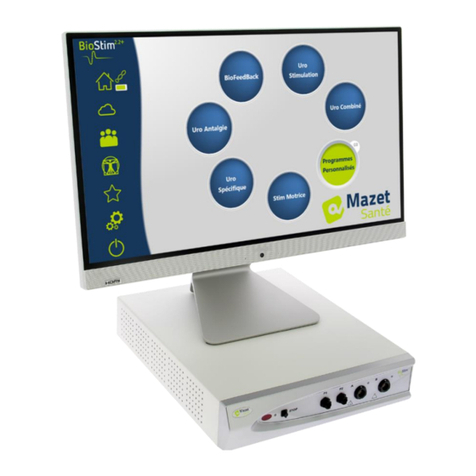
Mazet Sante Biostim 2.2+ User manual

Page 1 on 42 2022/09/27
MEG010XN102-A11 (ENG)
User Manual
Electrotherapy device
BioStim 2.2+
BioStim 2.1 / 2.1+
BioStim 2.0 / 2.0+
BioStim 1.0

Page 2 on 42 2022/09/27
MEG010XN102-A11 (ENG)
Instructions for use
&
Technical description
Please read these instructions carefully before using your new
device!
This manual is an integral part of the device and must be kept
until it is destroyed.
This equipment has been designed and manufactured for
therapeutic use.
The device is intended to be used only by physiotherapy
professionals and qualified midwives.
If you have a problem or do not understand this manual, please
contact your distributor (see stamp on the last page) or contact
Électronique du Mazet at :
Tel: (33) 4 71 65 02 16 - Fax: (33) 4 71 65 06 55
Please return the warranty certificate within 15 days of installation or
receipt.

Page 3 on 42 2022/09/27
MEG010XN102-A11 (ENG)
1Presentation of the device
The Biostim is an electrotherapy device that helps physiotherapists and midwives in perineal
rehabilitation.
The computerised technology used in the BioStim device makes it very easy to use and
navigate through the menus.
The programmes, predefined in the device, allow most perineal rehabilitation treatments to be
carried out in the urogynaecological and anorectal fields.
The main programmes available are
•Urogynaecological biofeedback, EMG or Pressure
•Urogynaecological stimulation
•Combined urogynaecological programmes, which combine biofeedback and stimulation
•Analgesia for urogynaecology
•Stimulation and anorectal biofeedback programmes
The device also allows individual follow-up of each patient, by memorising the sessions carried
out and their results, as well as by adding any comments or links to follow-up forms.

Page 4 on 42 2022/09/27
MEG010XN102-A11 (ENG)
Table of contents
1Presentation of the device......................................................................................................................3
2Description and technical information...................................................................................................5
2.1 Symbols used ..................................................................................................................................6
2.2 Technical specifications..................................................................................................................7
2.3 Nameplate label.............................................................................................................................10
2.4 Warnings.......................................................................................................................................11
2.5 Risks residual................................................................................................................................12
2.6 Confidentiality of patient data.......................................................................................................12
2.7 Cybersecurity................................................................................................................................13
3Installation of the appliance.................................................................................................................14
3.1 General positioning of the installation..........................................................................................14
3.2 Connection of accessories.............................................................................................................14
4Software commissioning .....................................................................................................................17
4.1 Configuration................................................................................................................................17
4.2 Software requirements ..................................................................................................................17
4.3 Installation.....................................................................................................................................17
4.4 Start-up..........................................................................................................................................18
4.5 Checking the connection...............................................................................................................18
4.6 In case of problems .......................................................................................................................19
4.7 Switching off the device ...............................................................................................................19
5User's manual.......................................................................................................................................20
5.1 Home page ....................................................................................................................................20
5.2 Programme selection and customisation page..............................................................................20
5.3 Programs specific to the + version................................................................................................21
5.4 Launching a programme ...............................................................................................................23
5.5 Favourite Programmes..................................................................................................................29
5.6 Anatomical Plates .........................................................................................................................29
5.7 Select a patient..............................................................................................................................29
5.8 Patient File ....................................................................................................................................30
5.9 Biostim Cloud...............................................................................................................................32
5.10 Configuration page....................................................................................................................32
6Clinical Guide......................................................................................................................................35
6.1 Target population..........................................................................................................................35
6.2 Expected clinical benefits .............................................................................................................35
6.3 Major contraindications ................................................................................................................35
6.4 Side effects....................................................................................................................................35
7Maintenance, servicing........................................................................................................................35
7.1 Housing and accessories ...............................................................................................................36
7.2 Sterilization :.................................................................................................................................36
8Malfunction..........................................................................................................................................36
9After-sales service and warranty .........................................................................................................38
10 Disposal ...............................................................................................................................................38
11 Transport and storage ..........................................................................................................................39
12 CE declaration .....................................................................................................................................39
13 Manufacturer........................................................................................................................................39
14 EMC compliance table ........................................................................................................................40

Page 5 on 42 2022/09/27
MEG010XN102-A11 (ENG)
2Description and technical information
- This user and maintenance manual is published to facilitate the handling of your BioStim from
the initial reception phase, through commissioning, to the successive stages of use and
maintenance.
If you have any difficulty in understanding this manual, contact the manufacturer, Électronique
du Mazet, your dealer or distributor.
- This document must be kept in a safe place, protected from atmospheric agents, where it
cannot be damaged.
- This document guarantees that the devices and their documentation are technically up-to-date
at the time of marketing. However, we reserve the right to make changes to the device and its
documentation without any obligation to update these documents.
- In the case of transfer of the device to a third party, it is obligatory to inform Électronique du
Mazet of the details of the new owner of the device. It is imperative to provide the new owner
with all documents, accessories and packaging relating to the appliance.
- Only personnel who have been informed of the contents of this document may use the
equipment. Failure to comply with any of the instructions contained in this document will
release Électronique du Mazet and its authorised distributors from the consequences of
accidents or damage to personnel or third parties (including patients).

Page 6 on 42 2022/09/27
MEG010XN102-A11 (ENG)
2.1
Symbols used
Warning: this logo draws your attention to a specific point
Operating instructions: This logo informs you that the operating
instructions must be read for safe use of the appliance
Type BF applied part: applied part in contact with the patient.
Recycling: This appliance should be disposed of at an appropriate
collection and recycling facility. Consult the manufacturer.
Protective earth
Fuse
Caution: Switching the appliance off and on
Alternating current
Serial number
Manufacturer
Date of manufacture
Product reference
Unique identifier
Medical device

Page 7 on 42 2022/09/27
MEG010XN102-A11 (ENG)
2.2
Technical specifications
2.2.1 General characteristics
•Operating temperature: 15°C to 40°C.
•Storage temperature: -20°C to 70°C.
•Operating relative humidity: 30% to 75%.
•Operating altitude: < 2000 metres
2.2.2 Technical characteristics of the device
•Case dimensions: 33.7 x 28 x 6.7 cm
•Case weight: 3.1 Kg
•Housing colour: white
•Power supply: 110-230VAC - 50-60Hz
•Power consumption: 55VA max
•Fuses: 2x size 5x20mm - T1.25AH-250V
•Class I electrical equipment
•Medical Class IIa equipment.
•Applied part type BF
•Liquid protection type IPX0.
•Communication with the PC: Optically isolated USB.
•Power on indication by a green light on the front panel.
•Possibility to stop the stimulation by an emergency stop bulb.
•1 or 2 Electro channels. Each channel has the following features:
•Current generator :
-Output currents of each generator adjustable from 0 to 100mA (+/-10%).
-Under a load impedance of 1kΩ(or more), at max current, the voltage is limited to
100V -20%/+10% (peak value).
-Under a load impedance of less than 1kΩ, the voltage level is limited according to the
impedance (10volts for 100Ω, 50volts for 500Ω)
-If the impedance is too high (above 10 kΩ), the current can be cut off: unstuck
electrode function
The rectangular shaped signals are biphasic (symmetrical pulses with zero average), the
pulse width is adjustable from 50µs to 10ms, the frequency is adjustable from 1Hz to
5kHz.
The generators are electrically independent (no current flows between the 2 electrodes of
the 2 generators).
Indication of the activation status of the output by a yellow LED.
•Biofeedback activity measurement: Full scale sensitivity: 2mV (peak-to-peak)
•0, 1 or 2 channel Biofeedback pressure
sensitivity range: 400 mBar

Page 8 on 42 2022/09/27
MEG010XN102-A11 (ENG)
2.2.3 Different versions of the device
The functionality of the different versions of the device is as follows:
Number of
Electro
channels
Number of
pressure
channels
Biostim 1.0
1
0
Biostim 2.0
2
0
Biostim 2.1
2
1
Biostim 2.2
2
2
Each version (except version 1.0) may have additional optional software features (version +).
These functions are described in section 7.3.
2.2.4 Accessories
This device is delivered with the following accessories as standard:
- MEG010EN601 Biostim electrode lead
- MEG010EN603 Biostim emergency stop bulb
- MEG010EN605 Blue Biostim pressure kit (optional)
- MEG010EN606 Red Biostim pressure kit (optional)
- EM6055KP504 IR REMOTE CONTROL (optional)
- 2m USB cable
- USB CLE (PC software / USB drivers)
- POWER CABLE
2.2.5 Applied parts
The applied parts, type BF, are vaginal probes, rectal probes or electrodes. They are not
supplied with the device.
List of products compatible with the device :
- Dura-Stick Plus Stimulation Electrodes (DJO Global) CE 0473
- Vaginal probe Saint-Cloud Classic (DJO Global) or Optima 3 (Sugar)
- Perifit or Fizimed CE probe.
- RectoMax rectal or Aerolys vaginal pressure probe
- Blueback (Blueback SAS)
- BioMoov (Electronique du Mazet)
The use of products not recommended by the manufacturer does not engage his responsibility
Make sure that the hygiene conditions recommended by the manufacturer of the
applied part are observed.
The user must pay particular attention and adapt the size of the electrodes to the
area to be treated

Page 9 on 42 2022/09/27
MEG010XN102-A11 (ENG)
Montée Plateau Descente Repos
2.2.6 Form of the currents
Two-phase rectangular pulses
The current is symmetrical biphasic with zero mean: the positive and negative pulses are of the
same amplitude and duration
The waveform is constant current and does not depend on the value of the load.
The pulse width is adjustable from 15µs to 10ms, the frequency is adjustable from 1Hz to
5kHz.
LF modulation (1Hz to 500 Hz) of the signal is possible.
The device complies with standard 60601-2-10: Medical electrical equipment: special
requirements for basic safety and essential performance of nerve and muscle stimulators. In
particular, this standard limits the delivered intensities as well as the powers per pulse.
Envelope generation :
The pulse signal is included in an envelope allowing a progressive application and cut-off of the
current
Peak amplitude (mA)
Pulse width (µs)
Signal period = 1 / Frequency (in Hz)

Page 10 on 42 2022/09/27
MEG010XN102-A11 (ENG)
2.3
Nameplate label
The information and characteristics are given on the back of each appliance on a label
Label for "Biostim 2.2+" : Label for "Biostim 2.1 / 2.1+".
Biostim 2.0" label Biostim 1.0" label
or "Biostim 2.0+":

Page 11 on 42 2022/09/27
MEG010XN102-A11 (ENG)
2.4
Warnings
CAUTION: Install the appliance on a flat, stable surface. Do not block any
ventilation openings (no objects closer than 4cm).
CAUTION: Power strips must not be placed on the floor. No other electrical
appliance or power strip should be connected to the power strip.
CAUTION: The appliance must be connected to an outlet with a grounding terminal
(Class I electrical appliance)
CAUTION: The unit must be positioned so that the mains cable is freely accessible
in case of emergency.
CAUTION: In case of emergency, disconnect the mains cable directly from the unit.
CAUTION: No modifications to the device are permitted. It is strictly forbidden to
open the housing of the device.
CAUTION: This equipment complies with applicable electromagnetic compatibility
standards. If you experience interference or other problems with another device,
contact Électronique du Mazet or the distributor for advice on how to avoid or
minimize the problem.
CAUTION: Operation in close proximity (e.g., 1 m) to shortwave or microwave
therapy EM equipment may cause instabilities in the output power of the
STIMULATOR.
CAUTION: The patient connected to the device must not be connected to other
equipment (monitoring or diagnostic equipment) during treatment. This may cause
interference with the ancillary equipment.
Simultaneous connection of a PATIENT to a high frequency surgical EM DEVICE may
cause burns at the contact points of the STIMULATOR electrodes, and the
STIMULATOR may eventually be damaged.
CAUTION: The appliance must be used with the accessories supplied by the
manufacturer.
CAUTION: If the PATIENT is equipped with an implanted electronic device (e.g.
pacemaker), the use of the device in pacing mode is IMPERATIVELY subject to prior
medical AUTHORISATION.
CAUTION: Applying electrodes between the chest and upper back (heart path), on
either side of the head, directly over the eyes, mouth, front of the neck (especially
the carotid sinus), may increase the risk of cardiac fibrillation.

Page 12 on 42 2022/09/27
MEG010XN102-A11 (ENG)
CAUTION: Under certain conditions, the effective value of the stimulation pulses
may exceed 10 mA and 10 V. Please follow the information in this manual carefully.
CAUTION: The user must pay particular attention and adapt the size of the
electrodes to the area to be treated.
ATTENTION:
It is important to check the size of the electrodes used.
The current density must be less than 2mA rms/cm².
CAUTION: The output signals of the device are biphasic symmetrical with zero
average and do not include a DC component. Any unpleasant sensation (irritation,
overheating) at low intensities could mean a defect in the equipment.
Do not use the device without the advice of the MANUFACTURER.
CAUTION: The device must not be accessible to the patient.
It should not be placed in contact with the patient.
CAUTION: If the computer used is not approved as a medical device, the computer
must not be located in a space accessible to the patient
2.5
Risks residual
To avoid the risk of burns or tetanization, be sure to disconnect the cables in the event of a
power failure or malfunction of the control PC.
Old or poor quality application parts can impair the quality of contact with the patient and cause
discomfort. Make sure you change them regularly.
Microbes or viruses can be transmitted from one patient to another via the applied parts. Make
sure that the hygiene conditions recommended by the manufacturer of the applied part are
observed.
If water enters the unit, it may not function properly. In this case, unplug the unit and
disconnect the cables. In any case, avoid the presence of water in the vicinity of the device.
2.6
Confidentiality of patient data
The device collects data from the computer to which it is connected. No data is stored in the
device.
It is the responsibility of the practitioner to apply and comply with the European Parliament's
General Data Protection Regulation 2016/679.
When returning to the Service Department, if the computer is returned with the device, the
practitioner must delete the patient data so that it is not disclosed. The practitioner has the
option of making a backup copy of this data by saving it to an external media before deleting it.

Page 13 on 42 2022/09/27
MEG010XN102-A11 (ENG)
2.7
Cybersecurity
As the device and its software Biostim are computerised systems integrated into larger
information systems, certain rules and good practices must be put in place to ensure the safety
of patients and users.
Électronique du Mazet does not supply or have control over the operating environment of its
products, it is therefore the responsibility of the practitioner to ensure that the following
recommendations are respected.
2.7.1 Good practices for IT security
•Keep your software up to date, including the operating system (Windows or MacOs)
•Use operating system accounts to prioritise access.
•Use strong passwords to access accounts
•Lock the computer when not in use
•Back up the Biostim database regularly
•Check the authenticity of the third-party software you install
•Use antivirus and firewall software
•Check regularly in the Cloud menu for updates
2.7.2 Technical information
•The Biostim software is a Java program
•The software configurations and the database are saved in the biostimdata folder of the
user folder (e.g. C:\Users\romain\biostimdata).
•The software uses port 61976 of the local loop (localhost / 127.0.0.1) to check that there
are not several instances of the software running at the same time.
•The software uses a proprietary USB driver to communicate with the device
2.7.3 Network communications
•The device does not require a network connection to operate
•If the user agrees (by checking the BiostimCloud option), data can be sent regularly to
the Electronique du Mazet servers
oAll these data are anonymised
oThey are only collected for statistical purposes, or to facilitate remote assistance
•The device can also communicate with the Electronique du Mazet servers, to find out if
updates are available, and if so, to update.
•All exchanges use a secure protocol (https)

Page 14 on 42 2022/09/27
MEG010XN102-A11 (ENG)
3Installation of the appliance
Open the carton, remove the accessories and the appliance.
Check the contents of the box against the packing list included with the documentation.
If the appliance was stored in a cold place and there was a risk of condensation, leave the
appliance to stand for at least 4 hours at room temperature, about 20°C.
Install the unit on a stand at working height.
3.1
General positioning of the installation
Place the Biostim on a table outside the patient's environment.
Place the PC on the same table and connect them via USB to the back of the unit
Connect the power cord to the back of the unit
The practitioner positions himself between the patient and the device
The patient lies on a massage table, or sits on a chair next to the practitioner
3.2
Connection of accessories
Connect the emergency stop bulb to the front panel.
Connect the pacing lead(s) to channel(s) A (and B) according to your application.
Operation
indicator
Emergency stop
valve
Remote
control
receiver
Tracks A and B
Stimulation and
Biofeedback
Channel connection
Pressure
Stimulation operation
indicators

Page 15 on 42 2022/09/27
MEG010XN102-A11 (ENG)
To use the pressure channels, connect the pressure kit to the pressure channels.
Place the electrodes or probe
on the muscle you wish to
work with, using the red and
black connectors
To do BFB, place the
3ème electrode (yellow
tip) on a bony part
(useless for
stimulation)

Page 16 on 42 2022/09/27
MEG010XN102-A11 (ENG)
A single balloon catheter (vaginal or anal) is then connected directly behind the tap to the P1
line.
For a double balloon anal probe, rectoMax type, connect the large balloon to the P1 channel
(blue kit), and the small balloon to the P2 channel (red kit)
On a Biostim 2.1 (or 2.1+), which has only one pressure channel, connect only the small
balloon to channel P1 of the device.

Page 17 on 42 2022/09/27
MEG010XN102-A11 (ENG)
4Software commissioning
4.1
Configuration
The device connects to a computer with at least the following characteristics:
-Windows 8, 10 or 11, or MacOS
-Intel Core i3
-4 GB RAM
-Recommended resolution: at least 1366*768
-To use an accessory (Blueback, BioMoov, Emy or Perifit), it is necessary to have a PC
running Windows 10 or 11 equipped with a BlueTooth card
4.2
Software requirements
The following software must be installed on the computer:
-Java 8 version 64 bits ( https://www.java.com/fr/download/ )
-FTDI Driver (installation by CDM21228_Setup.exe delivered with the software)
-Foxit PDF Reader
If not already present on the computer, the installation files are available on the USB stick in
the "drivers" directory.
4.3
Installation
Install the program on the desktop by double clicking on the installation utility (or
installation.cmd) at the root of the key.
This creates a BiostimData directory on the desktop (which will contain all patient data), as well
as a Biostim shortcut (or Biostim.exe).

Page 18 on 42 2022/09/27
MEG010XN102-A11 (ENG)
4.4
Start-up
Turn the on/off switch on the back of the unit to ON "1".
Check that the green power indicator light on the front of the unit is on.
Run the Biostim program on the PC
4.5
Checking the connection
Check that the connection is established: green home button.
The red home button indicates a communication problem between the PC and the device. In
this case, check the following points:
•The module is powered up, the green light on the front panel is on.
•The USB cable is properly connected to the device and the PC.
•The FTDI driver is correctly installed (CDM21228_Setup.exe )
The orange home button indicates a problem with the emergency stop bulb:
•Check that the emergency stop valve is connected
•If the emergency stop has been activated, the BioStim must be restarted (on/off switch at
the back of the device)

Page 19 on 42 2022/09/27
MEG010XN102-A11 (ENG)
4.6
In case of problems
Go to the "About your Biostim" page (via the configuration menu)
This page gives information about the problem and also allows you to report problems or
suggestions by e-mail.
4.7
Switching off the device
Disconnect the patient from the applied parts beforehand.
Exit the Biostim program on the PC (symbol )
Turn the on/off switch on the back of the unit to OFF "O".

Page 20 on 42 2022/09/27
MEG010XN102-A11 (ENG)
5User's manual
5.1
Home page
On launch, the software opens to the home page, which provides access to all the device's
features.
From any page of the application, pressing the home button will take you back to this page.
It is possible to rename a category by right-clicking on the desired category.
5.2
Programme selection and customisation page
Clicking on a programme category opens the programme selection page.
This page displays a list of all programmes in a category.
The button of the selected programme is highlighted and its description is displayed on the
right side of the page. This description contains :
•The name of the programme
•The duration of the programme
•A brief description
In the case of a stimulation programme, the current parameters are also included
In the case of a biofeedback programme, this includes
•the biofeedback profile
•the choice of animation
•the possibility to choose to display also the channels that will be used (1 or 2)
Home button
Green: OK
Red: no connection
Select a patient
Anatomical Plates
Favourite Programmes
Configuration
Exit
Links to the
programmes, sorted
by category
Quick launch
button
Selection of
favourite
programmes
Creating a user
program
Total duration of
the programme
Settings for a
stimulation
programme
Resetting the
settings
Connecting a BT accessory
Search for updates
Give your opinion on
the software
This manual suits for next models
3
Table of contents
Other Mazet Sante Medical Equipment manuals
Popular Medical Equipment manuals by other brands

HYPERICE
HYPERICE Normatec 3 Let's get started

Stryker
Stryker 1550 Operation manual

Weinmann
Weinmann VENTIlogic LS Instructions for use

NeoMedLight
NeoMedLight BiliCocoon Instructions for use

Basic American
Basic American ZENITH Series Instructions for use

Ethicon Endo-Surgery
Ethicon Endo-Surgery ENSEAL G2 manual