GF Health Products, Inc. - www.grahamfield.com Zenith 5000 Service Manual 999-0856-190C - DEC. 2013
4
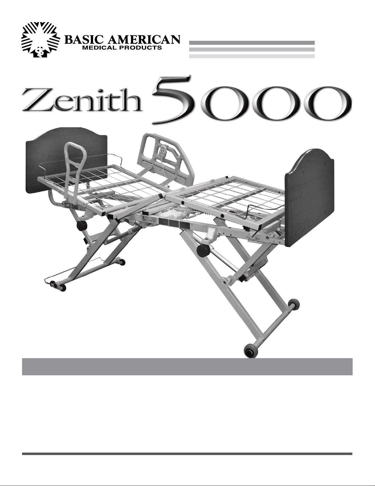
ZENITH SERIES
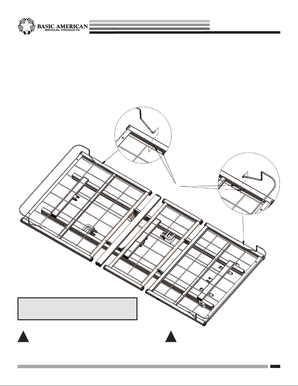
This product is a variable height, adjustable mattress
platform, which will provide comfort and convenience
for residents/patients and caregivers in long term
care settings.
The MAXIMUM SAFE WORKING LOAD for the
Zenith 5000 Bed with weight evenly distributed,
including bedding, resident/patient, support surface,
and all accessories, is 500 lbs.
NEVER operate the bed if a Power Cord or Plug is
damaged or not working properly. Contact qualified
Service Personnel for examination and repair. Always
unplug the Power Cord when performing any mainte-
nance on the bed.
DO NOT open assemblies such as the Actuators, Hand
Control, or Control Box. If unauthorized personnel
perform work on these components, the manufacturer’s
warranty becomes void.
DO NOT use unauthorized parts, accessories, or
adaptors other than those specified/authorized by
GF Health Products, Inc.
When operating the HI/LO, Knee, or Back Functions
of the bed, ALWAYS ensure that the confined individual
is positioned properly within the confines of the bed.
DO NOT let any extremities protrude over the side or
between the bed rails when performing these functions.
DO NOT lower the bed when objects are beneath it.
Failure to inspect under the bed can result in damage
to property or personal injury.
The bed’s Pendant Cord MUST BE ROUTED AND
SECURED PROPERLY to ensure it does not become
entangled and eventually severed during use. Also
make sure all electrical cords DO NOT get tangled
around the bed, side rails, or legs during transport or
normal operation of the bed.
When using nasal-type or masked-type administering
equipment, all oxygen or air tubing MUST BE ROUTED
AND SECURED PROPERLY to ensure that the tubing
does not become entangled and eventually severed
during the normal operation of the bed.
Keep all moving parts free of obstructions (i.e. blankets/
sheets, heating blankets/pads, wiring, etc.).
Beds manufactured by Basic American Medical Products
are designed for use within an institutional healthcare
environment (i.e. assisted living, skilled nursing, tran-
sitional care, rehabilitational care, etc.).
DO NOT use the assist devices as push handles for moving
the bed. Assist devices can be deformed or broken if
excessive side pressure is exerted. Assist devices are not
meant for patients considered as high risks for entrapment
(i.e. patients with pre-existing conditions such as
confusion, restlessness, lack of muscle control, altered
mental status, either organic or medicinal, or a combi-
nation thereof). Additional safety measures should be
considered for such high-risk patients.
NEVER permit more than one (1) person on/in the bed
at any time.
Body weight should be evenly distributed over the
sleeping surface of the bed. DO NOT allow the patient
to lay, sit, or lean in such a way that their entire body
weight is placed only on the raised head or foot sections
of the bed. This especially applies when repositioning
or transferring a patient in or out of the bed. Increased
risk may occur when the patient’s size and/or weight are
inappropriate for the bed’s dimensions or weight capacity.
Risk of entanglement or injury may occur if the mattress
used with mattress retainers does not fill the entire width
between stops or which compresses to less than 1.50
inches under user’s weight.
Mattress must be properly sized to fit the mattress support
platform and must remain centered on the support platform
relative to State and Federal guidelines. Recommended
minimum dimensions of mattress is 35 inches wide and
6 inches deep. Length should match the mattress support
platform. Use of an improperly fitted mattress could
result in injury or death.
IMPORTANT: Powered air mattress surfaces may pose
a risk of entrapment. Prior to use, ensure the therapeutic
benefits outweigh the risk of entrapment.
The bed is intended for use, storage, and transport within
a temperature range of -40˚C to +60˚C. It has a water-
resistance rating of IPX6 and IS NOT to be power-
washed or submersed.
!
!
!
!
!
!
!
!
!
!
!
!
!
!
!
!
!
!
IMPORTANT SAFETY AND WARNING INFORMATION