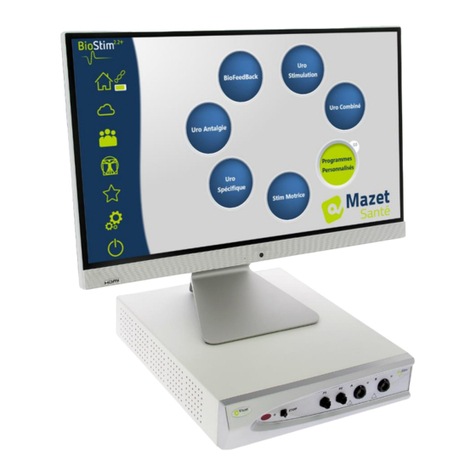
Mazet Sante Biostim 2.2 User manual

Page 1 of 40 12/04/2022
MEG010XN102-A10
User Manual
Electrotherapy Device
Biostim 2.2 / 2.2 +
BioStim 2.1 / 2.1+
BioStim 2.0 / 2.0 +
Biostim 1.0

Page 2 of 40 12/04/2022
MEG010XN102-A10
Instructions for Use
&
Technical Description
Please read this entire manual carefully before using
your new device!
This manual is an integral part of the device and must
be kept until it is destroyed.
This device was designed and manufactured for
therapeutic use.
Only physiotherapy professionals and midwifes with
proper training are authorised to use this device.
In the event of a breakdown, or if you have questions that are not
answered in this manual, please contact your distributor (see stamp on
last page) or Électronique du Mazet at:
Tel.: (+33) (0)4 71 65 02 16 - Fax: (+33) (0)4 71 65 06 55
Please complete the warranty certificate within the 15 days following
installation or reception.

Page 3 of 40 12/04/2022
MEG010XN102-A10
1. Device Presentation
The Biostim is an electrotherapy device that physiotherapists and midwives employ in perineal
re-education.
Biostim’s computerized technology and user-friendly menus make it very easy to use.
The device's pre-set programmes allow you to perform most perineal re-education treatments,
and treatments in the urogynaecological and anorectal fields.
The main pre-set programmes are:
•Urogynaecological biofeedback, EMG or Pressure
•Urogynaecological stimulation
•Urogynaecological programmes that combine biofeedback and stimulation
•Analgesia for use in urogynaecology
•Programmes for anorectal stimulation and biofeedback
The device also allows you to track each patient individually by recording the sessions carried out
and their results, letting you add comments, and providing links to tracking forms.

Page 4 of 40 12/04/2022
MEG010XN102-A10
Table of Contents
1. Device Presentation .............................................................................................. 3
2. Description and Technical Information ................................................................... 5
2.1 Symbols Used................................................................................................. 6
2.2 Technical Specifications................................................................................... 7
2.3 Nameplate Label........................................................................................... 10
3. Warnings............................................................................................................ 11
4. Potential Risks .................................................................................................... 13
5. Device Installation .............................................................................................. 13
5.1 General position of the installation................................................................. 13
5.2 Connection of the accessories........................................................................ 14
6. Commissioning the Software................................................................................ 16
6.1 Configuration................................................................................................ 16
6.2 Required pieces of software .......................................................................... 16
6.3 Installation................................................................................................... 16
6.4 Start-up ....................................................................................................... 16
6.5 Check of the connection................................................................................ 17
In case of problem................................................................................................. 18
6.6 Switch off your device................................................................................... 18
7. User Manual ....................................................................................................... 19
7.1 Home Page .................................................................................................. 19
7.2 Program Selection and Customisation Page .................................................... 19
7.3 Specific programs to the + version ................................................................ 20
7.4 Launching a Programme ............................................................................... 21
7.5 Favourite Programmes .................................................................................. 27
7.6 Anatomical Charts......................................................................................... 27
7.7 Select a Patient ............................................................................................ 27
7.8 Patient Records ............................................................................................ 29
7.9 Biostim Cloud ............................................................................................... 31
7.10 Configuration Page ....................................................................................... 31
8. Clinical Guide...................................................................................................... 33
8.1 Target Population ......................................................................................... 33
8.2 Expected Performance .................................................................................. 33
8.3 Major Contraindications................................................................................. 33
8.4 Side Effects .................................................................................................. 34
9. Maintenance, Servicing........................................................................................ 34
9.1 Housing and Accessories ............................................................................... 34
9.2 Sterilization .................................................................................................. 34
10. Malfunction ..................................................................................................... 34
11. After-sales Service and Warranty ...................................................................... 36
12. Scrapping........................................................................................................ 36
13. Transportation and Storage .............................................................................. 37
14. EC Declaration of Conformity............................................................................ 37
15. Manufacturer................................................................................................... 37
16. EMC Scorecard .........................................................Erreur ! Signet non défini.

Page 5 of 40 12/04/2022
MEG010XN102-A10
2. Description and Technical Information
- This manual was written to facilitate the use and maintenance of your Biostim device, from
reception, to commissioning, to the successive stages of use, to maintenance.
If you have questions that are not answered in this manual, please contact the manufacturer,
Électronique du Mazet, or your dealer or distributor.
- This document must be kept in a safe place, protected from the elements, where it will not be
damaged.
- This document ensures that the devices and their documentation are up-to-date technically at
the time of sale. However, we reserve the right to make changes to the device and its
documentation, without obligation to update the present documents.
- In the event that the device is transferred to a third part, you must provide Électronique du
Mazet with the contact details of the device's new owner. It is imperative that you provide the
new owner with all of the device's documents, accessories, and packaging.
- Only personnel who have read the present document are authorised to use this device. Non-
compliance with any of the instructions contained in this document exempts Électronique du
Mazet and its authorized distributors from the consequences of accidents or injury to personnel
or third parts (for example, patients).

Page 6 of 40 12/04/2022
MEG010XN102-A10
2.1 Symbols Used
Warning: This symbol draws your attention to a specific point.
Operating Instructions: This symbol informs you that the operating instructions
must be read in order to use the device safely.
Applied Part, Type B: Applied part that comes in contact with the patient and can
be earthed.
Recycling: This device must be disposed of at an appropriate recovery and recycling
facility. Contact the manufacturer.
Protective Earth
Fuse
Warning: Device Stop / Start
Alternating current
Serial number
Manufacturer
Date of manufacture
Country of manufacture
Product reference

Page 7 of 40 12/04/2022
MEG010XN102-A10
2.2 Technical Specifications
2.2.1 General Characteristics
•Operating temperature: 0°C to 40°C.
•Storage temperature: -40°C to 70°C.
•Operating relative humidity: 30% to 75%.
•Operating altitude: < 2000 metres
2.2.2 Technical Specifications of the Device
•Dimensions of housing: 33.7 x 28 x 6.7 cm
•Weight of housing: 3.1 kg
•Housing colour: white
•Electrical power supply: 110-230 VAC –50-60 Hz
•Absorbed power: 40VA max (230VAC)
•Fuses: 2x size 5x20mm - T1.6AH-250V
•Class I electrical device
•Class IIa medical device
•Type BF Applied Part
•Liquid Ingress Protection Rating: IPX0
•Communication with computer: Optically isolated USB
•Green "ON" indicator light on front panel.
•It is possible to connect a handheld emergency stop that stops stimulation.
•2 stimulation tracks (A and B)
•Current generator:
- The output currents for each generator are adjustable from 0 to 100 mA (+/-10%)
- Under a load impedance of 1kΩ (or more), at the max. current, the tension is limited
to 100V +10%-20% (peak value)
- Under a load impedance inferior of 1kΩ, the tension level is limited according to the
impedance (10 Volts for 100Ω, 50 Volts for 500Ω)
- In the case of a too high impedance (above 10kΩ), the current can be cut of: function
electrode removed
Rectangular signals are biphasic (mean-zero symmetric impulsions), the impulsion width is
adjustable from 15µs à 10ms, the frequency is adjustable from 1Hz to 5kHz.
The two generators are electrically independent, no current passes between the two
electrodes of the two generators.
Yellow LED indicates the output's activation state
•2 biofeedback tracks (A and B).
→Full-scale sensitivity: 2mVcc
•0, 1 or 2 Biofeedback pressure track
→Sensibility range: 400mBar

Page 8 of 40 12/04/2022
MEG010XN102-A10
2.2.3 Biostim different versions
The functionalities of the different versions of the Biostim are the following:
Number of EMG
tracks
Number of
pressure tracks
Biostim 1.0
1
0
Biostim 2.0
2
0
Biostim 2.1
2
1
Biostim 2.2
2
2
Each version (except the version 1.0) can have the optional functionalities of the software (+
version). Those functions are described in the section 7.3.
To activate the + version, enter the activation key in the debug page (click on the monkey
wrench in the configuration page).
2.2.4 Accessories
The standard version of this device comes with the following accessories:
- MEG010EN601 cable for A and B tracks Biostim
- MEG010EN603 Handheld emergency stop Biostim
- MEG010EN605 Blue pressure kit Biostim (option)
- MEG010EN606 Red pressure kit Biostim (option)
- EM6055KP504 Infrared remote control (option)
- USB2-102B USB cable 2m blue or grey
- USB KEY 2.0 1 Go (PC Software / Drivers USB)
- Power cord
- User manual
2.2.5 Applied Parts
Applied parts include vaginal probes, rectal probes, and electrodes. They are not supplied with
the device.
The following products are compatible with the device:
- Dura-Stick® Plus Self-Adhesive Electrodes for stimulation (DJO Global) CE 0473
- Saint-Cloud Classic vaginal probe (DJO Global) CE 0473
- PINK Perifit probe (Perifit)
- Emy probe (Fizimed)
The use of products not recommended by the manufacturer exempts the manufacturer from
liability.
Make sure to respect the hygiene conditions recommended by the applied parts
manufacturer.
The user must be careful and adapt the size of the electrodes to the zone to treat.

Page 9 of 40 12/04/2022
MEG010XN102-A10
Rise Plateau Descent Rest
2.2.6 The currents form
Rectangular biphasic impulsions
The current is mean-zero biphasic symmetric:
- the positive and negative impulsions have the same width and time
Width of impulsion (µs)
Peak amplitude (mA)
Period of the signal = 1 (Frequency in Hz)
(Amplitude values assured for an impedance span from 200Ω à 2kΩ)
The form of the wave is a constant current and it does not depend on the value of the load.
The width of the impulsion is adjustable from 15µs to 10ms, the frequency is adjustable from
1Hz to 5kHz.
The BF modulation (1Hz to 500 Hz) of the signal is possible.
The current IRMS (in mA)= I peak (in mA) x 2 x the width of impulsion (in s) x frequency (in Hz)
Generation of the envelopes:
The impulse signal is included in an envelope that make an application and a progressive stop of the
current.
Frequency of the impulsions
Peak amplitude maximum
≤ 400Hz
50mA
> 400Hz to ≤ 1500Hz
80mA
> 1500Hz
100mA

Page 10 of 40 12/04/2022
MEG010XN102-A10
2.3 Nameplate Label
The nameplate label on the back of each device provides information and characteristics.
Label of the “Biostim 2.2” or “Biostim 2.2+”:
Label of the “Biostim 2.1” or “Biostim 2.1+”:
Label of the “Biostim 2.0” or Label of the “Biostim 1.0”
“Biostim 2.0+”:

Page 11 of 40 12/04/2022
MEG010XN102-A10
3. Warnings
WARNING: Install the device on a flat and stable surface. Do not obstruct the
ventilation openings (no objects within 4 cm).
WARNING: The multi-socket power strips must not be laid on the ground. No other
electrical device, nor another power strip, may be connected to the device's power
strip.
WARNING: The device must be plugged into a socket with an earth terminal (Class I
electrical device).
WARNING: The device must be positioned in such a way as to ensure that the power
cable remains accessible in the event of an emergency.
WARNING: In the event of an emergency, unplug the power cable directly from the
device.
WARNING: No modification of the device is authorised. Opening the device's housing
is expressly prohibited.
WARNING: This device complies with applicable electromagnetic compatibility
standards. If you notice that your device malfunctions in the presence of another
device, due to interference or otherwise, contact Électronique du Mazet or your
distributor for advice on how to avoid or minimize potential problems.
WARNING: Using the device with a close proximity (ex: 1m) from an EM DEVICE of
short-waves or micro-waves can cause instabilities of the STIMULATOR output power.
WARNING: The patient using the device must not be using other devices (monitoring
or diagnosis equipment) during the treatment. Those devices could be perturbated.
The simultaneous connection of a PATIENT to an EM DEVICE of high-frequency surgery
can cause burns at the contact points of the electrodes connected to the STIMULATOR,
and the STIMULATOR can be damaged.
WARNING: This device must be used with the accessories supplied by the
manufacturer.
WARNING: If the PATIENT has an electronic implanted equipment (ex: a cardiac
pacemaker), using the stimulation mode of the device must OBLIGATORY be subjected
to a medical AUTHORIZATION before.
WARNING: Using electrodes between the thorax and the upper back (ride of the
heart), on both sides of the head, directly on the eyes, on the mouth, on the neck
(particularly the carotid sinus), can increase the risk of cardiac fibrillation.

Page 12 of 40 12/04/2022
MEG010XN102-A10
WARNING: In some conditions, the efficient value of the impulsions of
stimulation can exceed 10mA and 10V. Please scrupulously respect the
information given in this manual.
WARNING: The user must lend a particular attention and adapt the size of
the electrodes to the zone to treat.
WARNING: It is important to verify the size of the electrodes. The relative
gravity of the current must be inferior to 2mA rms/cm².
WARNING: The output signals of the device are mean-zero biphasic
symmetric and do not have continuous component. Every unpleasant sensation
(irritation, heating), from the lower intensities can mean that the device is
defective. Do not use the device without the opinion of the MANUFACTURER.
WARNING: This device must not be accessible to the patient. It must not be
placed in contact with the patient.
WARNING: If the computer used is not approved as a medical device, the
electrotherapy device must under no circumstances be located in a place that is
accessible to the patient.
WARNING: The circular connector put on the back side of the device is dedicated to
the diagnosis and the maintenance. It must not be connected to a power supply or to
another device not recommended by the manufacturer.

Page 13 of 40 12/04/2022
MEG010XN102-A10
4. Potential Risks
In the event of a power failure, or if the control computer malfunctions, be sure to disconnect
the cables in order to avoid the risk of burning or tetanisation.
Applied parts that are too old or of poor quality can affect the quality of the contact with the
patient and cause discomfort. Be sure to replace them regularly.
Microbes and/or viruses can be transmitted from one patient to another via the applied parts. Be
sure to follow the instructions for proper hygiene conditions recommended by the manufacturer
of the applied part.
If water gets into the device, it could malfunction. If water gets into the device, disconnect the
device and the cables. In any case, avoid having water in close proximity to the device.
5. Device Installation
Open the cardboard packaging, remove the accessories and the device.
Check the contents of the box by looking at the packing list included with the documentation.
If the device was stored in a cold environment and there was a risk of condensation, allow the
device to rest at room temperature, approx. 20°C, for at least 4 hours.
Install the device on a support that is at working height.
5.1 General positioning of the installation
Put the Biostim on a table outside the environment of the patient.
Put the PC on the same table and connect them together with the USB cable at the back side of
the device.
Plug the power cord at the back side of the device.
The practitioner places himself between the patient and the device.
The patient is laid down on a massage table, or sat down on a chair next to the practitioner.
Remote control
receiver
Indicator of
operation
Indicator of operation
for the stimulation
A and B tracks for the
stimulation and the Biofeedback
Connection of the pressure
tracks
Handheld emergency
stop

Page 14 of 40 12/04/2022
MEG010XN102-A10
5.2 Connection of the accessories
Connect the handheld emergency stop on the front side.
Connect the cable(s) of stimulation on the track(s) A (and B) according to your use.
Put the electrodes on the
muscle we want to work on.
To do Biofeedback, put the 3rd
electrode (yellow connector) on a
bone (not necessary for the
stimulation)

Page 15 of 40 12/04/2022
MEG010XN102-A10
To use the pressure tracks, connect the pressure kit on the tracks.
Next the probe is directly connected on the back of the tap.

Page 16 of 40 12/04/2022
MEG010XN102-A10
6. Commissioning the Software
6.1 Configuration
The device will connect to a computer with at least the following minimum requirements:
- Windows 7, 8, or 10
- Intel Core i3
- 4 GB RAM
- Recommended resolution: at least 1366*768 (minimum 1280 * 720)
- To use Bluetooth accessories (Blueback, BioMoov, Emy or Perifit), it is necessary to
have a PC under Windows 10 or 11 and equipped with a Bluetooth card
6.2 Required pieces of software
The following pieces of software must be installed on the computer:
- Java 8 64 bits ( https://www.java.com/fr/download/ )
- FTDI Driver (installation by CDM21228_Setup.exe given with the software)
- Foxit PDF Reader
If they were not already installed on the computer, the installation files are available on the USB
key in the folder named « install ».
6.3 Installation
Install the programme on the desktop with a double click on the software installation.cmd (at
the root of the key).
This operation creates a folder named biostim on the desktop (which will contain all the patient
data), as well as a shortcut biostim.exe.
6.4 Start-up
Position the on/off switch on the rear of the device to ON "1".
Check that the green ON indicator light on the front of the device is lit.
Run the Biostim.exe program on the computer.

Page 17 of 40 12/04/2022
MEG010XN102-A10
6.5 Check of the connection
Check that the connection has been established: the Home button will turn green.
The red home button indicates a communication problem between the PC and the device. In this case,
check the following points:
✓The module is powered on, the green indicator light on the front of the device is lit.
✓The USB cable is properly connected to both the device and the computer.
✓The FTDI driver is correctly installed (CDM21228_Setup.exe).
The orange home button indicates a problem with the handheld emergency stop:
✓Check that the emergency handheld stop is connected
✓If the emergency stop has been used, the Biostim must be restarted (on/off
switch on the back side of the device)

Page 18 of 40 12/04/2022
MEG010XN102-A10
In case of problem
Go to the page “About your Biostim” (through the configuration page)
This page gives information on the problem. Problems can be escalated, and suggestions can be
done be email in this page.
6.6 Switch off your device
First disconnect the patient from the applied parts.
Exit the programme Biostim on the PC (symbol ).
Switch off the device using the button on the back side (put it on OFF “O”).
If the version is well activated, the button “Custom Programs” appears on the Home
page.

Page 19 of 40 12/04/2022
MEG010XN102-A10
7. User Manual
7.1 Home page
When launched, the software opens on the home page, which gives access to all the features of the
device.
From any page of the application, a press on the home button will bring you back to this page.
7.2 Program Selection and Customisation Page
Clicking on a category of programmes opens the programme selection page. This page displays
the list of all the programs in a category.
Clicking on one of the buttons will select a programme, highlight the selected button, and
display its description on the right side of the page. This description contains:
•The programme's name
•The programme's duration
•A brief description
Descriptions of stimulation programmes also feature the parameters of the applied
current.
Biofeedback programme description includes:
•the biofeedback profile
•the choice of the animation
•the option of also displaying the tracks which will be used (1 or 2).
Quick launch button
Total duration of
the programme
Selection of the
favorite programs
Creation of a user
programme
Reset parameters
Parameters for a
stimulation
program
Home button
Green: OK
Red: no connection
Select a patient
Anatomical Plates
Favorite Programs
Configuration
Exit
Links to programs,
sorted by category
Connecting a BT accessory
Search for updates
Give your opinion on
the software

Page 20 of 40 12/04/2022
MEG010XN102-A10
The programmes’ parameters can be adjusted using and buttons.
Once you have customised the programme as desired, it can be saved by clicking the
button.
Registered programmes are recognizable because their name begin with “U:”. They are at the
root of the programmes list.
7.3 Specific programs to the + version
7.3.1 Version +: Adjustable profile
Permits to define the profile’s settings and to adjust them in real time during the exercise.
1
1
2
3
5
4
2
3
4
5
Viewing the exercise
profile
Choice of the
channels to be used
for the main and
the secondary
channel. It is
possible to mix
EMG and pressure
Choice of the type
of animation to
use
Allows you to choose
whether the cursor or
the background
image moves
This manual suits for next models
4
Table of contents
Other Mazet Sante Medical Equipment manuals
Popular Medical Equipment manuals by other brands

Arden Medical
Arden Medical Urias Air Splints Instructions for use

Dräger Medical
Dräger Medical Fabius GS Rail manual

Smiths Medical
Smiths Medical SurgiVet V3404 Plus Operation manual

Itamar Medical
Itamar Medical OM2196336 Operation manual

Gymna
Gymna CRYOFLOW ICE-CT user manual

Interacoustics
Interacoustics Micromedical Orion installation instructions