Wilson Wolpert WDC-300 User manual

Manual
WDC-300
COUNTER FOR WPP-300

0. PREFACE 3
1. FRONT PANEL, REAR PANEL AND KEYS 4
1.1 Front panel 4
1.2 Rear panel 5
1.3 Keys 5
1.4 Scale interface 6
1.5 RS232 interface 6
1.6 Foot switch and edge detector 7
1.7 Printer interface 7
2. TERMINOLOGY 8
2.1 Coordinate 8
2.2 Edge/crosshair mode, auto/manual mode 8
2.3 Measurement mode 8
2.4 Saving features 8
2.5 User program 10
2.6 Inputting value 10
2.7 Coordinate skewing 10
2.8 Storing parameters when power fails 10
2.9 Measure Easy 10
2.10 Measuring /presetting/constructing graphical features 10
2.11 Showing message of graphical features 11
3. BASIC OPERATION 13
3.1 Getting started 13
3.2 Resetting display value of a certain axis 13
3.3 Finding midpoint 13
3.4 Absolute/Incremental mode conversion 14
3.5 Imperial/Metric mode conversion 14
3.6 Polar/Cartesian conversion 14
3.7 Edge/Crosshair conversion 15
3.8 Auto/Manual conversion 15
3.9 Browsing graphical features 15
3.10 Storing graphical features 15
3.11 Recalling graphical features 16
3.12 Printing operation 16
4. EXAMPLES FOR MEASUREMENT 17
4.1 Interior system setting 17
4.2 Measuring coordinate of skewing angle 18
4.3 Measuring circle 18
4.4 Measuring angle 19
5. MEASURING AND CONSTRUCTING FEATURES 21
5.1 Measuring point feature 21
5.2 Measuring line feature 22
5.3 Measuring circle feature 22
5.4 Measuring distance feature 23
5.5 Measuring angle feature 24
5.6 Measuring with Measure Easy 24
5.7 Measuring coordinate of skewing angle 25
5.8 Constructing graphical feature 25
Manual WDC-300 1
CONTENTS

6. PRESET 32
6.1 Getting started 32
6.2 Presetting the current coordinate position 32
6.3 Presetting point feature 32
6.4 Presetting line feature 33
6.5 Presetting circle feature 33
6.6 Presetting distance feature 34
6.7 Presetting angle feature 34
6.8 Presetting the coordinate skew angle's value 34
6.9 Presetting datum point 35
7. INTERIOR SYSTEM SETTING 36
7.1 Getting started 37
7.2 Clearing all temporary features 37
7.3 Clearing all permanent features 37
7.4 Clearing all user programs 37
7.5 Clearing one special user program 38
7.6 Setting up Measure easy 38
7.7 Setting up angle format to DMS 38
7.8 Setting up angle format to DD 38
7.9 Setting up backward annotation mode 39
7.10 Setting up forward annotation mode 39
7.11 Setting up the number points of measuring a point feature 39
7.12 Setting up the number points of measuring a line feature 39
7.13 Setting up the number points of measuring a circle feature 40
7.14 Setting up the count direction of one srecial axis 40
7.15 Resetting the WDC-300 all parameters 40
7.16 Setting up axes' scale resolution 41
7.17 Setting up compensation mode 41
7.18 Setting up linear compensation 42
7.19 Setting up nonlinear compensation 42
7.20 Setting up user program 43
7.21 Setting up pre-scale coefficient 43
7.22 Setting up printer port 44
7.23 Setting up RS232 format 44
7.24 Setting up use format of RS232 45
8. CREATING, EDITING AND RUNNING USER PROGRAM 46
8.1 Creating user program 46
8.2 Editing user program 48
8.3 Running user programs 49
9. CORRESPONDING 50
9.1 BCD code format 50
9.2 ASCII code format 51
9.3 PRINT format 51
*ACCESSORIES 52
A. Specification 52
2Manual WDC-300

MOUNTING AND MAINTENANCE
0.1 ENVIRONMENTAL CONDITIONS
(1) Avoid exposing WDC-300 under the Sun or high temperature environment, and
operating temperature is 0°C to 40°C.
(2) Keep far away from high voltage, large current or strong magnetic machines;
(3) Scale signal cable should be kept far away from power cable;
(4) Avoid installing in the oil, water or dust and high vibration environment;
(5) Keep away from corrosive chemical.
0.2 ATTENTION
(1) Finding something wrong with WDC-300, please contact Rational Corporation or it's
agents instead of opening WDC-300's enclosure.
(2) Never open the WDC-300's enclosure and the optical plug if the power is on
(3) Confirm WDC-300 is connected to ground
0.3 MAINTENANCE
(1) Shut off the power supply when clean WDC-300
(2) Cleansing with dry cloth or cotton;
(3) Don't clean the external shuck with toluol or aether;
(4) Cleaning screen with alcohol or neuter detergent.
0.4 WARRANTY
We guarantee maintenance WDC-300 with the factory's original warranty. You should
return the warranty card to our company. The valid warranty card must be filled with the
specific model, machine model and install data.
Manual WDC-300 3
0PREFACE

1.1 FRONT PANEL
1. Zero axis and angle
2. LED display windows: Display numerical data of X-axis, Y-axis, Z-axis and angle
3. View additional information of a feature
4. Set up system
5. Feature storage and recall
6. LCD display window Feature message or menu prompts
7. Move information of features of menus
8. Print the feature or program to RS232 printer or to centronix printer.
9. Data divide by 2.
10. NUMERIC KEY: For numerical data entry
11. COMMAND KEYS: Begin or end data entry sequences
12. Preset new points or creat new features.
13. Creat or modify program.
14. Measure points
15. Measure lines
16. Measure radius, diameter and centroid location of circle or arc
17. Measure relative distance
18. Measure angles
19. Define original point
20. Avoids length by manual alignment or fixturing
21. Toggles between polar and certesian modes
22. Toggles between inch and millimeter
23. Toggles between absolute zeropoint and an incremental datum
24. Toggles between edge and crosshair modes
25. Toggles between automatic and manual modes.
4Manual WDC-300
1. FRONT PANEL, REAR PANEL AND KEYS
12 3
8
5 6 7
9
10
11
4
12
2122
23
24
2513 14 15 16 17 18 19 20

1.2 ILLUSTRATION OF REAR PANEL
1.3 DESCRIPTION OF KEY FUNCTIONS
Key mark Key name description
1Xº Yº Qº Zero axes Set the selected axis' display value to zero
21/2 find the middle point Display value of selected axis is divided
by 2
3INC/ABS Absolute/Incremental Toggle between Incremental
conversion and Absolute Modes
4INCH/MM Metric/Imperial Toggle between imperial mode and
selection metric mode
5POL/CART Polar/Cartesian Toggle between Polar
conversion coordination and Cartesian coordination
6EDGE/+ Edge/Crosshair Toggle between Optical Edge
conversion mode and crosshair mode
7AUTO/MAN Auto/Manual Toggle between automatic mode and
conversion manual mode
8PROG User program Enter user program function
9PRESET Preset Preset X/Y axis, preset feature
10 STORE Store Store temporary feature as permanent
feature
11 RECALL Recall Recall a permanent feature as temporary
feature a0
12 PRINT Print Print current feature or WDC-300 display
content
13 SETUP Setup Setup entry
14 ENTER/YES ENTER Confirm inputted value or operation
15 CANCEL/NO CANCEL Cancel the last inputted value or operation
16 FINISH Finish Finish measure operation or other
17 QUIT Quit Give up an operation
18 0-9 Numeric Number keys
19 .Decimal point Decimal point
20 +/- +/- sign Plus or minus sign
21 Scroll up and down Browse features or function's menu
22 MORE View more Show more information
23 ORG Set datum Set datum point
24 POINT Point feature Probe point feature
25 LINE Line feature Probe line feature
26 CIRCLE Circle feature Probe circle feature
27 DIST Distance feature Probe distance feature
28 ANGLE Angle feature Probe angle feature
29 SKEW Skew Rotate the coordinate with a certain angle
Note: The shadow word indicates key in WDC-300, and so as following.
Manual WDC-300 5
Amounting trestle
Power switch
Power socket
PrinterFoot switch of
edge detector
Scale input
RS232

1.4 LINEAR SCALE PIN DESIGNATION
(1) 9 pin
Pin no. Signal Wire color
1 +5V Red
2 0V Black
3 A+ Brown
4 B+ Yello
5 ABSI Orange
6
7
8
9 FG Shield
(2) 15 pin (optional)
Pin no. Signal Wire color
1 +5V
20V
3 A+ Brown
4 B+ Yellow
5NC
6FG
7-14 NC
15 ABS+
(3) 7 pin (optional)
Pin no. Signal Wire color
10V
2NC
3 A+ Brown
4 B+ Yello
5 +5V
6 ABS+
7FG
1.5 RS232 PIN DESIGNATION
Pin no. Signal Wire color
1 GND
2 TXD
3 RXD Brown
4 NC Yellow
5NC
6-9 NC
6Manual WDC-300

1.6 FOOT SWITCH AND EDGE DETECTOR
pin designation
PIN Signal Color of cable Description
1 FT1-1 Red 1. he foot switch operate such as when you press the
ENTER key, it will be ON or OFF state.
2 FT1-2 Red
3 FT2-1 Brown 2. The foot switch operate such as the FINISH key.
4 FT2-2 Brown
5 EXT0-PLUS Yellow 3. The edge detector cause latching (the external
electric current cause isolated)
6 EXT0-RTN Orange
7 EDGE-PS Blue 4. The edge detector cause latching (TTL Level)
8 EDGE-GND Black
9NC
1.7 PRINTER PIN DESIGNATION
15 PD is the standard outlet, however, the 25 PD is optional.
(1) 15PD outlet
PIN Signal Color of cable
1 STROBE Red
2 D0 Brown
3 D1 Yellow
4 D2 Orange
5 D3 Blue
6 D4 Purple
7 D5 Gray
8 D6 White
9 D7 Green
10 ACK Pink
11 BUSY Azury
12~15 GND Black
Manual WDC-300 7

(2) 25PD outlet(optional)
PIN Signal Color of cable
1 STROBE Red
2 D0 Brown
3 D1 Yellow
4 D2 Orange
5 D3 Blue
6 D4 Purple
7 D5 Gray
8 D6 White
9 D7 Green
10 ACK Pink
11 BUSY Azury
12 GND Black
13~17 NC
18~25 GND Black
Note:
The pin designation about include that the 15 pin outlet can
Change to 25 pin outlet.
8Manual WDC-300

2.1 COORDINATE
(1) Incremental/Absolute coordinate
Absolute coordinate is the basic coordinate.
Incremental coordinate is coordinate which is relative to the absolute coordinate.
(2) Polar/Cartesian coordinate
Cartesian coordinate expresses a point with (x, y).
Polar coordinate expresses a point with (ρ, θ).
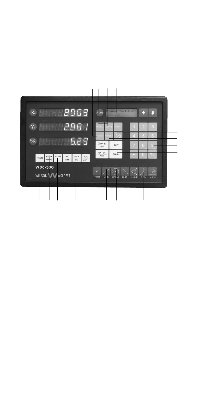
Example: " Current Position" is displayed in the message window
X window displays 1.000
Y window displays 2.125
Indicates that the current position is (1.000, 2.125) in Cartesian coordinate,
and it is (2.349, 64.799) in polar coordinate.
Note:
(1) The italics with '____'indicate that it is a terminology, the same as following.
2.2 EDGE/CROSSHAIR MODE, AUTO/MANUAL MODE
In Crosshairs mode, the display values of X window and Y window are updated
continuously, yet in Edge mode, they are update only when the Optical Edge Detector
are moving from dark area to light area or from light to dark. If WDC-300 is in the Edge
mode and AUTO mode at the same time, sample points will be probed automatically
and user needn't put the ENTER key; otherwise, the Enter key must be pressed to catch
sample point.
2.3 MEASUREMENT MODE
WDC-300 has two Measurement Modes: Forward Annotation Measurement and
Backward Annotation Measurement. The Forward Annotation Measurement means that
the number (less than 50) of sample points are preset before measuring, . In Backward
Annotation Measurement, it is not necessary for operator to setup the number of
sample points, the number of points is decided during the measuring. You can set the
measurement mode at interior setting.
2.4 SAVING FEATURES
Graphical feature is stored by two ways: temporary storing and permanent storing. The
temporary features will be lost when power is off, however the permanent features will
be kept for ever. So the permanent feature is used to save some used usually and
important features.
WDC-300 can store ten temporary features from a0 to a9 and one hundred permanent
features from 00 to 99. The current feature will be temporary feature a0 after
measurement is finished, and the last a0 will be changed into a1, and the rest
temporary features will does the same way. The last a9 will be lost. The temporary
feature can be changed into the permanent feature by store operation and the
permanent feature also can be recalled as temporary feature a0.
Manual WDC-300 9
2. TERMINOLOGY

2.5 USER PROGRAM
WDC-300 provides user program. User can create his own program, which makes
measurement very quickly and conveniently.
Adopting E2PROM, WDC-300 has a capacity of 10 user programs which No is from 0 to
9. Each user program can contain 100 steps from 0 to 99, and one user program can
invoke another user program, the invoked layers are utmost 10 layers.
2.6 INPUTTING VALUE
Press ENTER to confirm after inputting value. Press QUIT to give up value and quit. Press
the CANCEL to cancel the last inputted key, and you can also press ENTER at the
beginning to enter the preset value which is shown on the message window.
2.7 COORDINATE SKEWING
In order to improve measurement precision and make the measurement conveniently,
WDC-300 provides coordinate skew function, which help user skew work-piece.
When work-piece's shape is irregular or there is an angle between work-piece's edge
and X axis or Y axis, WDC-300 skew X-axis or Y-axis to the edge of work-piece to
improve measurement precision and the measurement convenience.
2.8 STORING PARAMETERS WHEN POWER FAILS
WDC-300 can store parameters when power fails. It can restore the failure state if the
power is supplied again.
Note:
(1) Temporary feature will be lost automatically if power failed.
(2) Linear scale cannot be moved after power fails.
2.9 MEASURE EASY
WDC-300 provides a function-Measure Easy. When the Measure Easy is open, the
system can create a feature only inputting some points. Of course, some rules should
be remember:
1. Input only one point, and then press "Finish" if you want to measure a point.
2. Input two points and then press "finish", you will get a line feature.
3. If you input three or more than three points, system would calculating that the
graphics is a circle or a line.
4. Measure Easy could not be used to measure distance feature and angle feature.
2.10 PRESETTING, MEASURING AND CONSTRUCTING FEATURES
WDC-300 provides 3 methods ---- preset/ construct/measure to obtain a new graphical
feature.
Preset: Users input value from panel, then WDC-300 gets message of feature.
Measure: WDC-300 get message of feature after it deals with the data get form
scale. .
Construct: User uses existent features to construct a new feature (including
temporary feature and permanent feature).
10 Manual WDC-300

2.11 SHOWING FEATURE'S MESSAGE
Graphical features' message can be viewed in different ways from Cartesian coordinate
and polar coordinate
1. Point feature
(1) In Cartesian coordinate, the point feature is displayed with X offset value and Y |
offset value from datum point.
Example: " a0 Point X/Y " is displayed in the message window
1.000 is displayed in the X window
1.000 is displayed in the Y window
It indicates a0 is a point, its coordinate data is (1.000, 1.000) in cartesian,
and it can be changed into (1.414, 45.000) in polar.
(2) In polar coordinate, the point feature data is displayed by the distance from the
point to the datum point and the angle between positive direction of X axis and the
line from datum point to the sampled point.
Example: " a1 Point r/a" is displayed in the message window
1.414 is displayed in the X window
45.000 is displayed in the Y window
It indicates a1 is a point feature, its coordinate is (1.414, 45.000) in polar,
and it will be changed into (1.000, 1.000) in cartesian coordinate.
2. Line feature
The line feature will be displayed with it's one point element which is nearest from
datum point and the angle between the line and positive direction of X axis.
Example: " a1 line X/Y " is displayed in the message window
1.000 is displayed in the X window
-1.000 is displayed in the Y window
It indicates a1 is a line, the cartesian coordinate of the point is (1.000, -1.000) which
is nearest from datum. It will be changed into (1.414, 315.000) in polar.
Press MORE," <… " is displayed in the message window
45.000 is displayed in the X window
It indicates the angle between this line and x axis' positive direction is 45.000°.
3. Circle feature
A circle feature consists of its central point and its radius.
Example: "00 circle X/Y" is displayed in the message window
1.000 is displayed in the X window
1.000 is displayed in the Y window
It indicates the first permanent feature is a circle, the center of the circle
(1.000, 1.000) in Cartesian coordinate, and it will be changed into (1.414, 45.000) in
Polar coordinate.
Press MORE, " r/d…" is displayed in the message window
2.000 is displayed in the X window
4.000 is displayed in the Y window
It indicates the radius of the circle is 2.000 and the diameter is 4.000.
4. Distance feature
The distance feature is the offset values of X axis and Y axis between two point
features.
Example: " 00 offset X/Y " is displayed in the message window
1.000 is displayed in the X window
1.000 is displayed in the Y window
It indicates that the first permanent feature is a distance feature, the offset value of
X is 1.000, and the offset value of Y is 1.000.
Press the MORE, " Distance " is displayed in the message window
1.414 is displayed in the X window
It indicates the distance between two points is 1.414.
Manual WDC-300 11

5. Angle feature
Angle feature is an angle between two lines.
Example: " 02 Angle <12 " is displayed in the message window
45.000 is displayed in the X window
315.000 is displayed in the Y window
It indicates the first permanent feature is an angle feature, and its value is 45°.
Press MORE, " <34…" is displayed in the message window
135.000 is displayed in the X window
225.000 is displayed in the Y window.
12 Manual WDC-300

Description:
1. Normal monitor state:
It is a state that message window display "Current Position" or "Last Edge Cross",
and it also indicates the state of showing the message of feature after operation is
finished.
3.1 GETTING STARTED
Introduction
WDC-300 will automatically enter self-test state when power is on. Pressing any key or
waiting until self-test finished, message window display " Move Near X RI…" if
nonlinear compensation mode has been selected for X-axis. Move the linear scale near
to the RI point, then press ENTER key, "Search X RI…" will be displayed in the message
window. Move the linear scale to RI point, at this time, "RI Found…" is displayed in the
message window, which indicate that the RI point of the X-axis is found. Repeat the
above steps if nonlinear compensation mode has been selected for Y-axis. WDC-300
will enter normal monitor states after the above is finished. When WDC-300 works
normally, it can recall the followings:
A. The last position when power was off;
B. ABS/ INC Mode;
C. MM/ INCH Mode;
D. CART/ POL Mode;
E. EDGE/CROSSHAIRS Mode;
F. AUTO/MANU Mode;
G. Whether WDC-300 is in skew state or not.
3.2 CLEAR (ZERO)
Function description:
When WDC-300 is in normal monitor state, user can setup the current position
as the datum point,. And the new display value will be 0.000.
Operating steps:
1. Return the normal monitor state;
2. Press X0 to reset X axis display value,
Press Y0 to reset Y axis display value,
Press Q0 to reset Z axis or Q axis' display value.
Note:
(1) User can't reset display value when WDC-300 is in other states.
(2) User can reset display value either in INC mode or ABS mode.
(3) If user reset in ABS mode, the value in INC mode is also reset; however,
if user resets in INC mode, the value of ABS mode doesn't change.
3.3 FIND MIDPOINT
Function description:
Divide the current display value by 2,then user can set datum point at the middle point
of the work-piece.
Example:
make the midpoint of work-piece to be the datum point of X-axis.
Manual WDC-300 13
3. BASIC OPERATION

Operating steps:
1. Return the normal monitor states;
2. Place the Optical Edge Detector on one edge of the work-piece, then press X0.
3. Move the Optical Edge Detector to another edge of the part, and press 1/2 ;
" Axis to Half" will be displayed in the message window.
4 Press X0 and the operation is finished.
5. Move to the point whose displayed value is 0.000,and the point is the middle of the
work-piece.
Note:
If you want to find the midpoint of Y-axis and Q-axis, press Y0 or Q0 in the step 5.
3.4 ABS/INC CONVERSION
Function description:
toggle between ABS mode and INC mode
Operating steps:
1. Return normal monitor states;
2. Press INC/ABS to change mode.
Note:
(1) You can't set up INC/ABS mode before that you return the normal monitor state.
(2) If the light above INC/ABS is on, the current coordinate is INC.
3.5 METRIC/IMPERIAL CONVERSION
Function description:
toggle between metric mode and imperial mode.
Operating steps:
1. Return normal monitor states;
2. Press INCH/MM to change mode.
Note:
(1) Only in the normal monitor state, you can change Metric / Imperial mode.
(2) The current working mode is Imperial if the light is on.
3.6 POLAR/CARTESIAN CONVERSION
Function description:
toggle between Polar mode and Cartesian. Mode.
Operating steps:
1. Press POL/CART to change mode.
2. Press POL/CART to change mode.Note: (1) Only in the normal monitor state,
you can change Polar/Cartesian mode.
Note:
(1) Only in the normal monitor state, you can change Polar/Cartesian mode.
(2) The current working mode is Polar if the light is on.
14 Manual WDC-300

3.7 EDGE/CROSSHAIRS CONVERSION
Function description:
toggle between Crosshairs mode and EDGE detect mode.
Operating steps:
1. Return to the normal monitor states;
2. Press EDGE/+ to change mode.
Note:
(1) Only in the normal monitor state you can change Edge/Crosshair mode.
(2) The current working mode is Edge if the light is on.
3.8 AUTO/MANUAL CONVERSION
Function description:
toggle between AUTO mode and Manual mode.
Operating steps:
1. Return normal monitor states;
2. Press AUTO/MANU to change mode.
Note:
(1) Only in the normal monitor state you can set auto/manual mode.
(2) The current working mode is AUTO if the light is on.
(3) When AUTO mode is selected, EDGE mode must be selected too.
If Crosshairs mode is selected, you must select MANUAL mode.
3.9 BROWSE MESSAGE OF GRAPHICAL FEATURES
Function description:
To browse message of graphical features.
Operating steps:
1. Return normal monitor states;
2. Press or to browse message of features, and message is displayed in the
message window, X window and Y window.
Note:
User can't browse message of features until you return normal monitor state.
3.10 STORE OPERATION
Function description:
Save temporary feature or permanent feature as permanent feature.
Example:
Save temporary feature a1 as the 12th permanent feature.
Operating steps:
1. Return normal monitor states;
2. Press STORE key, " Store: 00" is displayed in the message window;
3. Press 1, 2, ENTER, input the destine No of permanent feature ;
Message window will display a feature. Example: " a0 Line X/Y", and its related
message is displayed in the X window and Y window; "Select Source..." is
displayed in the message window;
4. Press or to browse the feature's message which is displayed on message
Manual WDC-300 15

window, X window and Y window.
5. When user find message of a1, Press ENTER to let a1 as source feature, then store
operation is finished.
Note:
(1) User can't save features until you return the normal monitor state.
(2) According to different actual operation, the message displayed is different in step 2
and step3.
3.11 RECALL OPERATION
Function description:
Save the permanent feature as temporary feature a0.
Example:
Recall the twelfth permanent feature to temporary feature a0.
Operating steps:
1. Return to normal monitor state;
2. Press RECALL, " Recall:00" appears in the message window;
3. Press 1 2 ENTER to input source feature No, and the content of a0 is the copy of
No12 permanent feature;
Note:
(1) User can't recall features until you return normal moratoria state.
(2) In step 2, the message is displayed differently according to actual operation
(3) The destine of recall operation is temporary feature a0.
3.12 PRINTING
Function description:
Print user program or all graphical features
Example 1:
Print all graphical features
Operating steps:
1. Return normal monitor state;
2. Press PRINT, "Print prog" is displayed in the message window;
3. Press or until "Print Feats?" is displayed in the message window;
4. Press ENTER to print.
Example 2:
Print the first user program
Operating steps:
1. Return normal monitor state;
2. Press PRINT, "Print prog" is displayed in the message window;
3. Press ENTER, then "Prog Num:" is displayed in the message window;
4. Press 1to select the first user program;
5. Press ENTER to print.
16 Manual WDC-300

Manual WDC-300 17
Description
1. Initializing system setup include setting up measure unit, selecting coordinate and
annotation mode, the points' number of forward annotation mode needs.
2. Work-piece skewing include coordinate circle and coordinate move.
3. Introduce the circle's measure and the line's measure.
4.1 INTERIOR SYSTEM SETUP
If you are going to measure, please make sure that the followings have been setup.
1. Measure unit
You can use unit of MM or INCH to measure with WDC-300. Select a kind of unit
before you begin to measure. Please refer to 3.5. The default length unit is MM.
2. ABS and INC coordinate
Please refer to 3.4.
3. POL and CART coordinate
POL and CART coordinate display graphics using different modes. The default
coordinate system is CART. Refer to 3.6 if you want to change the coordinate mode.
And you can change it anytime also. In CART system, the offset length of X and Y
map on axis is displayed. In the POL system, a point will be explained with a length
from datum point and an angle.
4. Probing method
Feature points can be probed with crosshairs or an optical edge detector.
You can use auto-find-edge mode also. The default mode is crosshairs.
(Refer to 3.7 and 3.8)
5. Forward or backward annotation
Selecting annotation by steps as forward:
(1). Press setup, enter setup mode.
(2) Press and to browse menu until "Annotation" is displayed.
(3). Press ENTER, then "Back Annotation" is displayed.
(4). Press or until "Forw Annotation" is displayed.
(5). Press ENTER, there is a "" before annotation mode, which means this mode is
selected.
(6). Press FINISH to exit. And press FINISH again to quit setup.
6. Angle unit setting up
Angle's unit has two mode: DD and DMS. The forward steps display selecting:
Note:
DMS expresses a angle with ***°**' **" . 1°= 60' , 1' = 60"
DD expresses an angle with ***.*****°
(1). Press SETUP, enter setup.
(2). Press or to browse menu until "Angle Type…" is displayed.
(3). Press ENTER, "DMS Angle" is displayed.
(4). Press or until "DD Angle" is displayed.
(5). Press ENTER then a "v"is displayed before the mode on the screen,
which means this mode is selected.
(6). Press FINISH or QUIT twice to exit setup state, then return normal
monitor state.
7. Setting up the number of points to be probed.
If the forward annotation has been selected, you should set up the number of points
to be sampled:
(1). Press SETUP to enter setup, then "Clear…" is displayed
(2). Press or to browse menu until "Annotation…" is displayed.
(3). Press ENTER then "Back Annotation" is displayed.
(4). Press or to browse menu until "Point Pts 01?" is displayed.
(5). Press ENTER and then "Value:01" is displayed.
(6). Input the number you want to probe. For example, input 3 means that
measuring a point feature needs to probe three points.
4. EXAMPLES FOR MEASUREMENT

(7). Press ENTER, system return "Point Pts 03" menu.
(8). It is same to setup the number of points to get a circle feature or a line feature.
(9). Press FINISH or QUIT twice to exit setup state, then return normal
monitor state.
4.2 SKEW ALIGNMENT
Usually, we take it for granted that the workpiece is aligned on X axis or Y axis. An
improper aligned or "mis-skewed" workpiece will result in inaccurate measurement. It is
a better choice to use skew function when user start to measure a new workpiece.
User probes 2 - 50 points on the selected edge , then WDC-300 changes the display
coordinate automatically. The selected edge become X axis or Y axis in new coordinate.
steps:
(1). Press SKEW, then "Probe Line" is displayed and the light flashed.
(2). Probe three points at an edge. The sample point would be probed automatically
in auto mode and by pressing ENTER in manual mode.
(3). Repeat the above steps to probe enough points. Press FINISH when enough
points are sampled in forward annotation mode. User need not do press
FINISH in backward annotation, then "X (or Y) Axis Skewed" is displayed , when
the light is on but not flash. WDC-300 outputs display value in new coordinate
through complex calculation.
(4) Press POINT to determine a right point on the line as datum point. Press ENTER
when you select the point. If you probe enough points (you should press FINISH
after all points are probed), the system would determine the suitable point. Then
"a0 Point X/Y" is displayed, which means coordinate value of this point is
displayed on the X screen and Y screen. Press more to get more message.
(5). Press ORG to set new datum point. The light would be on and "Select Point" is
displayed. Then the feature probed last is displayed. (If there is no graphics,
"No Feat Selected" is displayed and then quit from system). Press or to
select a point or center of a circle or vertex of an angle .
(6). Press ENTER to determine the selected feature and then the new datum point is
set.
Note:
1 If you want to exit the skew state, please keep pressing the SKEW key for about 3 second.
2 If you want to see the previous coordinate that had not been skewed, just press the
SKEW key again. And press the SKEW key again, the WDC-300 will go back to the SKEW state.
4.3 MEASURING A CIRCLE
You can probe a minimum of 3 points and a maximum of 50 points when you measure
a circle, the points is on the circle or around accordingly. And if you want to measure a
circle preciously, you should probe at least 3 points, also the points is better to distribute
uniformity on the circle. You can determine the number of points to be probed in
backward annotation. When you measure the circle in forward annotation mode, the
required number points will be displayed on LED windows. If you probe more then 3
points the system will calculate the circle with a most suitable arithmetic. The following
will show you how to measure a circle in the forward annotation mode.
18 Manual WDC-300

(1). Press CIRCLE. Then "Probe Circle" and the number of points to be probed is
displayed on LED windows. If you press CIRCLE again, the required number will
increase with 1. (If WDC-300 is in backward annotation, the number you have
probed will be displayed.)
(2). Move the cross to the first point of circle, then press ENTER, the position of the
point will be displayed on X window and Y window, and the number of points to
be probed will decrease one.
(3). Repeat the steps to probe next point until enough points have been probed.
( If WDC-300 is in backward annotation, press FINISH after enough points have
been probed. Parameters of the circle will be calculated automatically and "a0
Circle R/D" will be displayed in message window which means that the circle is
saved as temporary feature a0, and the radius is displayed in X window,
diameter in Y window .
(4). Press MORE, "a0 Circle X/Y" is displayed in message window. This position of
the center is displayed in X window and Y window. Press MORE again,
"a0 Circle +T/-T" is displayed which means that parameter +T is displayed in X
window and -T in Y window.
4.4 MEASURING AN ANGLE
WDC-300 provides two methods to measure an angle: (1) to probe three points to get
an angle; (2) to probe 2 lines to get an angle.
1. To probe three points to get an angle
The first sampled point is the vertex of the angle, and then measure the second and
third point with anticlockwise direct. It is important that that the angle can't be more
than 180°. The following is the working steps:
(1). Press ANGLE, then the light is on. Now prepare to measure an angle when
"Probe Angle" is displayed.
(2). Press POINT, then the light on ANGLE flash continuously which means that
sampling three points to get an angle. "Probe 3 Points" is displayed on the
screen.
(3). Move the cross to the vertex of the angle and press ENTER to probe the first
point. The position of this point is displayed on the X window and Y window.
"1 Pts Probed" is displayed which means that first point is probed.
(4). Repeat the step (3) to probe another two points with anticlockwise direct.
(5). Press FINISH , and the measurement is completed. WDC-300 will calculate the
angle automatic and "a0 Angle <12" is displayed in message window.
The value of the angle is displayed in X window and the value of its
supplementary angle is displayed in Y window.
(6). Press MORE to get more message.
2. To probe 2 lines to get an angle.
Manual WDC-300 19
Table of contents