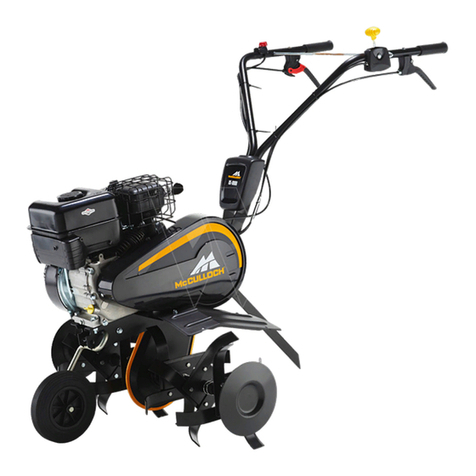
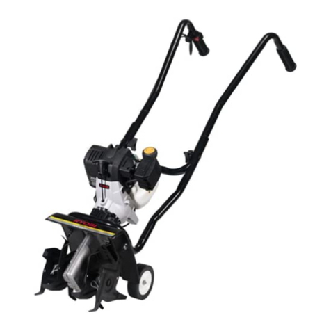
McCulloch MRT6 User manual

LtrtrULL trH
MRT6
o
0

14
36
46
55
58
I
2
3
4
5
6
7
Safety rules.
Sicherheitsvorschriften.
Règles de sécurité.
Assembly.
Zusammenbau.
Montage.
Start and operation.
Start und betrieb.
Mise en marche et conduite.
-
Maintenance.
Wartung .
Entretien.
Repair and adjustment.
Reparatur und einstellung.
Réparations et réglages.
Troubleshooting.
Störungssuche.
Recherche des pannes
Technical data.
Techinische daten-
Données techniqes.
Reglas de seguridad.
N orme antinfortunistiche.
Veiligheidsregels
Montaje"
Montaggio.
Montering. 7
Starten en rijden.
Aviamento e guida.
Arranque y cinducción
Onderhoud.
Manutenzione.
Mantenimiento.
Herstellen en afstellen.
Riparazioni e messa a punto.
Reparación y ajuste.
Búsqueda de averías.
Ricerca guasti.
Het localiseren van fouten
Technische gegerens.
Localización de averías.
Espicificaciones tecni cas.
3
We rcserue the right to make changes wlthout prior notice.
Ånderungen ohne vorherige Mitteilung sind vorbehalten.
Nous nous réservons le droit d'appoÉer des modifications sans avis préalable.

@ r. sAFETYRULEs
TRAINING
. Readthe irstructions carefully" Befamiliarwiththe conbols
and the proper use of the equipment;
. Never allow chìldren or people unfamiliar with these
instructions to use the machine, Local regulations can
restrict the age of the operator.
. Never work while people, especially children, or pets are
nearby.
. p in mind that the operator or user is responsible for
accidents or hazards occurring to other people or their
property.
PREPAIì/ATION
. Whileworking, always wearsubstantialfo ear and long
trousers. Do not operate the equipment when barefoot
or wearing open sandals.
. Thoroughly inspect the area were the equipment is to be
used and remove all obj which can bethrown by the
machine.
RNING: Petrol is highly flammable:
- store fuel in containers specifically designed for this
pur e;
- refuel outdoors only and do not smokewhile refu-
eling;
- addfuel orestartingtheengine.Neverremovethe
cap of the fuel tank or add petrol while the engine is
running or when the engine is hot;
- if petrol is spilled, do not attempt to s the engine
but move the machine awayfrom the area of spillage
and avoid creating any source of ignition until petrol
vapors have dissipated;
- replace all fuel tank and container caps securely.
. Fleplace faulty silencers.
. Beforeusing,alw visuallyinspecttoseethatthetools
are not worn or damaged. Replace worn or damaged
elements and bolts in sets to preserve balance.
OPERATION
. Do not operate the engine in a confined space where
dangerous carbon monoxide fumes can collect.
. Do notchangethe engine governorsettings or overspeed
the engine.
. Work only in daylight or in good artificial light.
. Alw be sure of your footing on slopes.
. Walk, never run.
. For wheeled rotary mach¡nes, work across the slopes,
slopes.
. Do not work on excessively steep slo
. Use o<trernecautionwhen reversing orprlling the machine
towards you.
. Do not run the engine indoors; exhaust fumes are dan-
. e engine carefully according to instructions and
with f well away from the tool(s)"
. Do not put hands or near or under rotating parts.
. Never pick up or carry a machine while the engine is
@I"SICHERHEfTS RSCHRIFTEN
SCHULUNG
. Auf keinen Fall Kindem oder Personen, die nicht mit d¡esen
sondere Kindern oder Haustieren arbeiten.
oder deren Eigentum ausges werden.
VORBERETUNG
. Bei der Arbeit immer feste
. Den Arbeitsbereich, in dem die Maschine betrieben werden
NUNG: Benln ist äußerst leicht enzündlicfr:
- ltaftstoff in besonders
rauchen.
oder heiB ist.
i-
-ssicher aufschrzuben.
um sicherzustellen, daß
BETRIEB
. Den Motor nicht in einem en n, in dem
I
betreiben.
. ,beiTageslicfrt oder guter lninstficfÞr Beleuchtung arbe-
: u"' Drehfräsen mit Rädern ""'åiJ::Itîi*",1*i.
.ne
nd
. Die FüBe und Hände nicht in die Nähe von oder unter dre-
. inen Fall anheben oder traoen solanoe

@ r. nÈcus oe sÉcun¡rÉ
FORMATION
PREPAIì.¡ATION
ENTON: Le combustible est très inflammade:
- Entre ez ie combus{ible dans des récipient spécíal
FONCTIONNEME
. Faites aüention de voûe position sur les pentes .
' e où quand
rotattves.
. Anêtez le moteur
- quand voLrs vor.rsi éloignez de la machine et avant de
@1. VEILIGHEIDSREGELS
INSTRUCTIES
ORBEREIDING
. WERKING
naar u toe trekt,
. De motor niet laten draaien binnenshub; uitlaatgassen zijn
de
len
. looit optillen of dragen terw¡jl de motor draait.

@ r. REcLAS DE sEGURTDAI
ENTRENAMIENTO
PREPARACION
ADVERTENCIA: El combustible es muy inflamable:
el motor este cal¡ente,
OPERACION
. Ande, nuca corra.
r onas.
. Nunca intente en bvantar o levante una máquina mienûas
que el motor este funcionando.
. Pare el motor:
1. NORME ANTINFORTUNISTICHE
ADDESTRAIIIENTO
. PREPARAAONE
- se del carburanteviene versato, non accendere il motore;
ir
o
e
. Sostituìre marmitte discarico d ose.
uso
ovi-
. Prestare la massìmaatterpio re i n sede di inversione di marcia
e
:;, moto.
o

@þ fnr"r symbols may appear on your machine or in the lit-
erature supplied with the product, Learn and understand
their meaning.
þ-fl Oio" Symbole finden Sie auf lhrer Maschine oder in Un-
- terlagen, die mit dem Produkt ausgehåndigt wurden" Bifte
machen Sie sich mit deren Bedeutung vertraut.
6È) C"" symboles peuvent se montrer sur votre machine ou
- dans les publications fournies avec le produit. Apprenez et
comprenez la signification des symboles.
N
@ *rg symbolen kunnen op uw machine of in de bij het
produkt geleverde documentatie aanwezig zijn. Ledr en
begrijp hum betekenis.
GÐ e"to" símbolos pueden apareÞr sobre su unidad o en la
- fiteratura proporcionada con el producto. Aprenda y com-
prenda sus significados.
@Simbolì utilizzati sull'apparato faciante o nella documenÞi-
one fornita con il prodotto. E' importante cononscerne bene
il significato.
c-
+R
F
TILLING
BODENFRÄSEN
FRAISAGE
VOORWAARTS
LABOREO
AEATURA
FRÄSNING
DYRKING
FRÆSNING
JYRSINTÄ
NEUTRAL
LEERI.AUF
POINl MORT
VRIJLOOP
NEUTRO
FOLLE
NEUTFAL
FRI
FFIGEAB
VAPA.AVAIHDE
REVEFSE
RÜCKWÄRTSGANG
]IIABCHE AFF¡ÈRE
ACHTEBUIT
REVÉS
RETROMARClA
BACK
REVEFS
BAKGEAR
PEFUUTUS
FAST
SCHNELL
RAPIDE
SNEL
RÁPIDO
VELOCE
SNABB
HURTIG
HURTIG
NOPEA
ENGINE OFF
iloroR Aus
iIOTEUF ARRÊTÉ
HOTOF UIT
HOTOR APAGADO
MOTOFE SPENTO
IHOTORN AV
IHOTORN AV
MOTOR STANDSET
MOOTIOFI POF
PAAIITA
WARNING
WARIIUNG
AVEBNSSE}IENT
WAARSCHUWNG
ATEI{CIC¡N
AWERTENZA
VARNING
ADVARSEL
ADVARSEL
vAFOTTUS
KEEP BYSTANf}EFS AWAY
ZUSCHAUEF FERNHALTEN
GAFDEZ LES SPECTATEURS
LOIN DE VOUS
OMSTAI{DERS UIT DE
BUUFT HOUDEN
GUARDESE LÉJOS DE GENTE
TENEFE LONTANI I PASSANTI
SE TILL ATT Ag(ADARE
BEFÍNNER SIG PÂ BEHORIGT
AVSTÁND
UVEDKOT,IIIENDE PEFSON ER
BøR HOLDES BORTE
HOU) TILSTEDEVÆRENDE
PÅ AFSTAND
PIDÄ OHIKULKUAT POIS
rÄperrYvrrrÄ
READ OWNERS MANUAL
BETFIEBSA NLE¡TU NG LESEN
LISEZ LE IIANUEL DU
PROPR!ETAIRE
GEB FUIKE FSHANDLEIDING
LEZEN
LEA EL MANUAL DE DTJENO
LEGGERE IL MANUALE
DELL'OPERÁTOFE
t.AS ANVANDAFHANDBO KEN
LES BFUKSANVISN!NGENE
UE S BETJENlNGSVEJLE DNIN GEN
LUE OMISTAJAN OHJEKIRJA
SLOTY
U\NGSAM
LENTE
LANGZAAT
LENTO
LENTO
ur¡os¡m
LANGSOH
LANGSOM
HIDAS
EUROPEAN IIACfIII'ERY
DIRECTIVE FOR SAFETY
EU ROPA ISCH E VEROR D}IUNG
FUR MA SCHI{ E1.}SICHERHEIT
DIRECTIVE POUB LA SECUBITE
DE MACHINE EUBOPEEN
V EILIGH EIDSR IC HTLUN V OOR
EUROPESE HACHINES
DIHECTIVO DE TIA OUINAR IA
EUROPEO PARA I-A SEGURIT¡AD
N ORIIATIVE ANTINFORTUNISTICH E
EUROPEE PER iIACCTIINARI
EUFOPE19( STANDAFD
FöB MASKlNSAKERHET
EUFOPEISKE
IIASKINSIK KER HETSF EGLER
FORWARD
VORWAFTSGANG
MARCHE EN AVANT
VOORUIT
IUIAFCHA HACIA
DELANTE
MAFCIA
FRAMÅT
FFAMOVER
FREMÂD
ETEENPÄIN
@C€ m
FN
RRN
F
F
Ê

@1. Gearcase notch
2. Handle lock
3. Handle (high position)
4. Shift lever
5. Handle (low position)
6. Handle lock lever
@ t. Getriebegehäuse-Aussparung
2. Handgriffsperre
3. Handgriff (obere Stellung)
4. Schalthebel
5. Handgriff (untere Stellung)
6. Hangriffsperrenhebel
Figwe 1
Abb. 1
1
2. Assembly 2.Zusalnmenbau
2. Montage 2. Montaje
2. ilontagg¡o 2. Montering
n
@ hstatt handte
a. lnsert one handle lock (with teeth facing outward) in
gearcase notch (fig. 1). Apply grease on smooth side of
in gearcase notch. Be careful not to stretch or kink
cables.
bly.Tighten
e. Place washer on threaded end of handle lock lever.
f. lnsert handle lock lever through handle e and gear
case (fig. 3-inset).
S. With handleassemblyin lowest ition, securelytighten
handle lock lever by rotating clockwise.
@Montage des Handgrifü
a. Eine Handgriffsperre (mit den Zähnen nach außen) in die
Aussparung des Getriebegenhäuses einpassen (Abb. 1 ).
Die glatte Seite der Handgriffsperre mit Fett schmieren.
Auf diese ise wird die Sperre in der Aussparung ge-
halten, bis der Griff angebracht worden ist.
b.
heddert werden.
c. Den Handgriff nach unten schwenken. Den hinteren Bol-
zen (abb. 3 ausschnitt) mit dem Bolzenkopf auf die linke
Seite der Bodenfräse gerichtet, zuerst anbringen. Den
senken. Die Bolzen so f iehen, daß die Handgrifie
beim Bewegen as Widerstand leisten.
schnitt).
e
Figwe 2
Abb.2
hândles_l
-Åu14
f

2
@
@r.
2.
3.
4.
5.
6.
7.
8.
ô
10.
.t 1.
12.
1. Shift rod
2. Hairpin clip
3. Shift lever indicator
4. Handle assembly
5. Carriage bolt and locknut
6. Handle base
7. Slot
8. Greasecase
9. Handle lock
10. Washer
1 1- Handle lock lever
12. Pivot bolt
@
@
ïre pressure
Reduce tire pressure to 20 PSI ff ires were overinflated for
shipping purposes). lf tire pressures are not equal, tiller will
pull to one side.
Oonnect sh¡ft rod
a. lnsert end of shift rod into hole of shift lever indicator-
b. lnsert hairpin clip through hole of shift rod to secure.
Anschluß der Schaltstange
a. Das Ende der Schaltstange in das Loch der
Schalthebelanzeige einseÞen.
b. Den Haarnadelsplint durch das Loch in der Schaltstange
frihren, um diese zu sichern.
Reifendruck
Reifenluftdruckauf ca. 1,4 bar absenken (Die Reifen werden
ñirTransportzwecke auf rlbermäßig hohen Druck aufgepumS).
Wenn die Reifendnicke nicht gleichmäßig sind, zieht die
Bodenfräse nach einer Seite.
lnset
Ausschn¡tt
Schaltstange
Haarnadelklemme
Schalthebelanzeiger
Handgrilfmontagesatz
Wagenbolzen und l(ontermutter
Handgriffplatte
Schlitz
Getriebegehäuse
Handgriffsperre
Unterlegscheibe
Handg riffs perren hebel
Gelenkbolzen
Figure 3
Abb 33
1
I
I
/l7L
0
11

2
@r2.
3.
4.
5.
6.
Encoche du carter de la e de vitesses
Couvercle du guidon
Guidon (positlon haute)
Levier de changement de vitesses
Guidon (position se)
Levier de blocage du guidon
@ ntage du guiclon
b.
Veillez a ne pas tirer ou embrouiller les càbles.
c.
encart).
e. Placez la rondelle sur la partie filetée du levier de blocage
du guidon.
cart).
Serrez le levier de blocage du guidon en letournant dans
le sens des aiguilles d'une montre.
@ Handvat monteren
a. Monteer de eerste hendelvergrendeling (met de tanden
naar buiten wijzend) in de sleuf in de schakelkast (fig.
b. Neem de hendeleenheid, en breng de is in de "up"-
c. Draai de hendeleenheid naar beneden- Monteer eerst
de achtersteslotschr (fig. 3 - inzet) met de schroefkop
aan de linkerkant van de cultivator. Monteer de voorste
zwenkbout. Laatdehendeleenheidzakken. Sch de
schroeven vast zodat de hendel bij het bewegen enige
weerstand biedt.
d. Monteer de tweede hendelvergrendeling (met de tanden
naar binnen wijzend) in de sleuf in de basis van de hendel
(fig. 3 - inzet).
e. Monteer de sluitring op het getapte uiteinde van de hen-
@r2.
3.
4.
5.
6.
Schakelkastsleuf
Hendelvergrendeling
Hendel (hoge positie)
Schakelhendel
Hendel (lage positie)
Hendelvergrendelingarm
Figure 1
Figwr 1
Figwe 2
Figuur 2
handles I
1
3/4
/.^ -/
nf n

2
@ t. Barre d'embrayage
2. Pince en épingle à cheveux
3. Assemblage du manche
4- Boulon à tête bombée et collet carré et contreécrou
5. Boulon de véhiclue et écrou de blocage
6. Base du guidon
7. Fente
8. Garter de la boîte de vitesses
9. Gouvercle du guidon
10. Rondelle
11" Levier de blocage du guidon
12. Boulon à pivot
@ r. schaketstang
2. Splitpen
3" Schakelhendelindicator
4" Hendeleenheid
5. Slotschroef en borgmoer
6. Hendelbasis
7. Sleuf
8- Schakelkast
9. Hendelvergrendeling
10. Sluitring
1 1 . Hendelvergrendeling hefuoom
12. Zwenkbout
Figre 3
Figrur 3
Press¡on des pneus
Abaissez la pression des pneus à 1.4 bar (les pneus sont
surgonflés pour le transport). Si la pression des pneus n'est
pas la même, la fraiseuse tirera vers un côté ou l'autre.
schakelstang monteÞn
a. Steek het einde van de schakelstang in het gat van de
schakelhendelindicator.
b. Steekde haarspeldklem door hetgatvan deschakelstang
om hem vast te zetten.
Bandendruk
Verminder de bandendruktot 1 .4 bar (de banden waren te hard
opgepomptvoor het transport)- Alle banden moeen dezelfde
bandendruk hebben, anders dan staat de cultivator scheef.
t$ontage de la barre d'embrayage
a. lnsérez l'extrémité de la tige de changement de vitesse
dans le trou de I'indicateur de levier de changement de
vitesse.
b. lnsérez le collier en épingle à cheveux à travers le trou
de la tige de changement de vitesse pour la fixer.
Encart
lnzet
1t
@
@
3
I
I
ß
o

2
@r.
2.
3.
4.
5.
6.
@r2.
3.
4.
6.
Muesca de caja de engranajes
Bloqueo del manillar
Manillar {posició alta)
Palanca de cambio
Manillar (posición baja)
Palanca de bioqueo de manillar
Tacca
Fermo del manubrio
M anubrio (posizione superiore)
Leva del cambio
Manubrio (posizione inïeriore)
Leva di fermo del manubrio.
@Instalación del manillar
a. lntroduzca un bloqueo del manillar (con los dientes hacia
afuera) en la muesca de la caja de engranajes (fiS. 1).
Aplique grasa al lado liso del bloqueo del manillar. Esto
ayudará a mantener el bloqueo en su sitio hasta que se
baje el manillar a su posición correcta.
b. Agarreel conjunto del manilla¡ muevala base del manillar
a la posición "alta' como muestra la figura 2. Asegúrese
de que el bloqueo del manillar queda en la muesca de
la caja de engranajes. Tenga cuidado de no estirar ni
retorcer los cables.
c" Gire el conjunto del mango hacia abajo. lntroduzca el
tornillo decarruaje posterior (fig.3 - detalle) primero, con
la cabeza del tornillo en el lado izquierdo de la cultivora.
Baje el manillar completo. lnserte el tornillo articulado
anterior. Apriete los tornillos, de forma que el manillar
se mueva con cierta resistencia,
d. I nlrodwca el segundo Hoqueo del manillar (con los dientes
hacia adentro) en la ranura de la base del manillar (fig.
3 - detalle).
e. Goloque la arandela en el extremo roscado de la palanca
de bioqueo del manillar.
f. lntroduzca la palanca de bloqueo del manillar a traves
de la base del manillar y la cala de engranajes (fig. 3
- detalle).
S. Con el manillarcompletoer su posiciónmás baja, apriete
firmemente la palanca de bloqueo girando en sentido
horario.
@ Montaggio del manubrio
a. Montare uno dei fermi (con i denti rivolti verso l'esterno)
nella tacca (fig. 1). lngrassare il lato sottile del fermo,
per tenerlo fermo a posto fino a quando il manubrio non
è alloggiato nella sua posizione definitiva.
b. Afferrare il manubrio, sollevando la base nella posizione
"upu come da figura 2. Assicurarsi che ìl fermo rimanga
a posto nella tacca. Non scchiacciare o tirare i cavi.
c Ruotareil manubrioversoilbasso. lnfilareprimailbullone
posteriore (fig. 3 inserto), con la testa sul lato Sinistro.
inserire il bullone snodato anteriore. Del motocoltivatore.
Abbassare il manubrio. Stringere il bullone in modo che
il manubrio si muova con una certa resistenza.
d. Montare il seondofermo del manubrio (con identi rivolti
verso l'interno) nella scanalatura alla base del manubrio
(fig. 3 inserto).
e. lnfilare larondella sull'estremità filetatta della leva del
fermo del manubrio.
f. lnf lare la ls¡adel fermo del manubrio attraverso la bæe del
Figura 1
Figure 1
Figua 2
Figure 2
handles 1
1
q4
r¡

2
@
@
1.
2.
3.
4.
5.
6.
7.
8.
9.
10.
11.
12.
1.
2.
3.
4.
5.
6.
7.
8.
9.
10.
11.
12.
Barra de cambio
Chaveta hendida
lndicador de palanca de cambio
Manillar completo
Tornillo de carruaje y tuerca de seguridad
E]¡ase de man¡llar
Ranura
caja de engranajes
Bloqueo de manillar
Arandela
Palanca de bloqueo de manillar
Tornillo articulado
Asta del cambio
Graffa a U
Selettore di marcia
Manubrio
Dado e bullone di fermo
Base del manubrio
Fessura
Scatola
Fermo del manubrio
Rondella
Leva del fermo
Bullone snodato
@ Montage de la bane d'embrayage
a. lnserte el extremo de la varilla de cambio en el agujero
del indicador de la palanca de cambio.
b. lnserte la abrazadera de horquilla a través del agujero
de la varilla de cambio para asegurarla.
Presión de neumáticoseum
ala
igua
tllontaggio dell'asta del cambio
a. lnserire I'estremità dell'asta del cambio nel foro
dell'indicatore della leva del cambio.
b. lnserire ilfermaglioiad U attmverso ilforo dell'a$adel
cambio per fissare.
Pressione dei pneumaticl
Ridurre la pressione a 1,4 bar (Le gomme sono a maggior
pressione per motivi di transporto). Se le ruote non hanno la
stessa pressione, il motocoltivatore tire da una parte.
Figura 3
Figure 3 3IÞtalle
lnseno I
e
10
'l

2
@r.
2,
3.
4.
5.
6.
7.
8.
9.
@
@r
@
Handle Bar
Throttle control
Shift lever
Drive control lever
Drive control release
Tine shield
Engine
Wheel
Model plate
1. Handgriff
2- Gashebel
3. Schalthebel
4. Antriebshebel
5- Entriegelung Antriebshebel
5. ZnkenschuÞ
7. Motor
8. Räder
9. Typenschild
1
4
Guidon
2. Accélérateur
3. Levier de changement de vitesse
4. Levier de commande de
I'enlraînement
5. Levier de dégagement de
l'entraînement
6. Protection des dents
7. Moteur
8. Roue
9. Palqued'identification
1. Hendel
2- Gashendel
3. Schakelhendel
4. Rijhendel
5. Rijhendelontgrendeling
6. Tandbeschermplaat
7. Motor
8. Wiel
9. Modelplaatje
@ t. Guía
2- Mando de aceleración
3. Palanca de cambio
4. Palancadecontrol delatransmisión
5. Desbloqueo de control de la trans-
mlston
6. Gubierta protectora de dientes
7. Motor
L Rueda
9. Chapa de modelo
@r"
2.
3.
4.
5.
6.
7.
8.
9.
Manubrio
Gomando del gas
Leva del cambio
Leva del comando di avanzamento
Sblocco del comando di avanza-
mento
Disco salvapiante
Motore
Route
Traghetta di indentifi cazione
7
5
I

3. Start and Operation 3. Start und Betrieb
3. Mise en marche et conduite 3. Starten en rijden
3. Aviamento e guida 3. Aranque y cinducción
@ t. oit tevet
2. Oilfiller plug
3. Fuel tank cap
@
@
NOTEI
Before operating your tillerfor thefirst time, study this section
and the "1. Safety instructions*.
Gheck englne oil level
a. With engine level, remove engine oil filler plug (fig- 4)
b. Engine oil should be to point of almost overflowing (fig
4). Engine oil capacity is about 1 'l/4 pints (20 ounces)
NOTE!
Be very careful not to allow dirt to enter the Engine when
checking oradding oil orfuel. Use clean 30or 10W-30 grade
oil and store in approved, clean covered containers. (Do
not use pressurized starting lluid, as severe internal engine
damage may occur due to loss of lubrication.)
Fill fuel tank
To fill fuel tank (fig. 5), use fresh, clean regular unleaded
automotive gasoline. Capacity is about 2.5 quarts.
HINITEIS!
Vor der ersten lnbetriebnahme der Bodenfråse sind die fol-
genden Punkte und "1. Sicherheitsvorschriften".
Ölstano im Motor Kontrollleren
a. Bei niedrigem Motorölstand Öleinfrlllschraube herauss-
chrauben (Abb 4).
b. Das Motoröl solte am Einfùllstutzen fast ûberlauTen (Abb.
4). Die Motorölmenge beträgt ca" 0,5 1.
HINWEIS!
Beim Kontrollieren oder aulfùllen des Mororöls, ist darauf
zu achten, daß kein SchmuÞ in den Motor gelangt. Es ist
sauberes 30 oder 10W-30 Motoröl zu ven¡renden und in
geeigneten, sauberen Kanistern zu venøahren. (Keine unter
ùu ck steh ende Startf lüss i g keit venruenden, da m ang elh afte
Schmierung schwere Motorschäden verursachen kann).
@1. Olstand
2, öleinfrlllschraube
3. Tankdeckel
Figre 4
Abb.4
Figure 5
Abb.5
\
2
1

3
@ t. Niveau d'huile
2. Bouchon de remplissage d'huile
3. Bouchon du réservoir d'essence
@ t. otiepeil
2. Olievuldop
3. Dop benzinetank
Figue 4
Figrur 4
Figue 5
Figur 5
@ neunnouer
Avant de conduire votre fraiseuse pour la première fois,
étudiez le présent chapitre et les n 1 . Cosignes de sécurité".
Vérifiez le niveau d'huile du moteur
a. Enlevez le bouchon de remplissage d'huile avec la jauge
d'huile (fig.4).
b. L'huile du moteur doit presque déborder (fig. a). La
capacité d'huile du moteur est d'environ 0.5 litres.
REIIARQUE!
Veillez bien à ne pas laisser entrer de saletés dans le mo-
teur lorsque vous vérifiez ou complétez le niveau d'huile
Remplbsage du réseiloir d'essence
Pourremplir le réservoird'essence (frg. 5) utilisezde I'essence
neuve, propre et ordinaire sans plomb pour automobiles. La
capacité du réservoir est d'environ 3 litres-
@N.B.!
Lees de volgende instructies goed door evenals de "'l^
Veiligheidsvoorschrlften", voor u de cultivator voor het eerst
gebruikt.
Controleer het motoroliepeil
a. Verwijder de vuldop voor de motorolie (fig. 4)
b. De motorolie moet bijna overlopen (fi9. 4)" De hoeveelheid
bedraagt ongeveer 0,6 liter.
I
2
1
N.B.!
*
Wees erg voorzichtigzodat ergeenvuil in de motorkomtwan-
-^^-.. L^¡ -t:--^:t ^^-t--t-^J -¡..--*-^--.- ^l:- ^¡L---l^¡-¡

3
@ f . Niveldeaceite
2. Tapón de llenado de aceite
3. Tapón de depósito de gasolina
1. Livello dell'olio
2- Tappo dell'olio
3. Tappo serbatoio carburante
Figura 4
Figure 4
@ r.rorx
Antes de utilizar su cultivadora por primeravez, estudie esta
sección y las "1. lnstrucciones de seguridad".
Control del nivel de aceite del motor
a. Con el motor en posición nivelada, quite el tapón de
llenado de aceite del motor (fiS. 4).
b. El aceite del motor deberá llegar a tal nivel que casi
rebose (fiS. 4). La capacidad de aceite del motor es de
aproximadamente 0.6 1.
NOTA!
Tenga mucho cuidado para que no entre suciedad en el
motor al controlar o rellenar aceite o combustible. Utilice
aceite limpio de calidad 30 ó 10W-30 y guarde en depósitos
y con tapa- (No utilic-e liquido de arranque
rÍa causar serios daños internos al motor
e lubricación).
Llene el depósito de gasollna
Para llenar el depósito, (fig.5) utilice gasolinaparaautomóvìles
limpia, regular y sin plomo. La capacidad es de aproxima-
damente 3litros.
@ norer
I
Prima dì usare il motocoltivatore
accuratamente le istruzioni e "-1. per la prima volta leggere
Disposizioni di sicurezza".
2
1
5
5
figura
Figure
Controllare il livello dell'olio
a- Togliere il tappo del serbatoio dell'olio (fig. 4)
b. L'olio deve essere quasi sul punto di fuoriuscire (fig. 4)
Volume di olio nel motore circa 0,6 litri.
NOTA!
Evitare I'ingresso di impurità nel motore attraverso il tappo
di rifornimento. Usare olio nuovo 30 o 10W-30 contenuto in
recipienti puliti e adeguati" (Non impiegare fluido per awia-

3
@r.
2.
3.
4.
5.
6.
7.
8.
9.
'10.
Starter handle
Choke lever
Spark plug wire
Shift lever indicator
Drive control lever "disengaged' position
Drive control lever "engaged' position
Drive control release "unlocked" position
Drive control release ulockedn position
Throttle control
Handle grip
Figue 6
Figwe 7
4
Stading the engine
a. Reconnect spark plug wire and cover (lig. 6).
b. Move shift lever indicatorto "N" (neutral) position (fiS. 4.
c. Place throttle control (fig. 8) in "FAST' position.
d. Place choke lever in "CHOKE" position (fig. 6).
e. Grasp starter handle (fig. 6) with one hand and grasp
handle bar with other hand. Pull rope out slowly until
engine reaches start of compression cycle (rope will pull
slightly harder at this point).
f. Pull ropewith a rapid, continous, full arm stroke. Keep a
firm grip on the starter handle and let rope rewind slowly.
Do not let starter handle snap back against starter.
S. Repeat steps (e.) and (f.) until engine starts. When engine
starts. Place choke lever on engine halfway between
"CHOKE' and "RUN'' position (fig. 6) and then move to
"RUN" position as engine warms up.
h. Movethrottle control (fig. 8) halfway between "FAST" and
"STOP" position for a few minutes to warm up.
WARNING!
Keep drive control lever in "disengaged" position when start-
ing the engine (fig. 8).
A
NOTE!
ln order to idle smoothly, a new engine may require 3 to 5
minutes runnig time above slow idle speed. ldle speed has
been adjusted to be correct after this break-in period.
Tine operation
a. Move throttle control to desired speed.
b. Tine movement begins when drive control lever is in
"engagedu position (fiS. 8).
ATYARNING!
Always release drive control lever before moving shift lever
into another positìon.
l:l Figure I

3
@r.
2.
3.
4.
5.
6-
7.
8.
9.
10.
Starthandgriff
Chokehebel
Zûndkerzenkabel und Keeenstecker
Schalthebelanzeiger
Antriebshebel " ausgekuppelt"
Antriebshebel'eingekuppelt"
Antriebshebel in "entriegelter' Stellung
Antriebshebel in "verriegelter" Stellung
Gashebel
Handgriff
Abb. 6
Motorstart
a. Zündkerzenkabel und Kerzenstecker (Abb. 6) lösen.
b. Schalthebel auf oNn (Neutralstellung) einstellen (Abb. 4.
c. Gashebel (Abb.8) "FAST" (schnell) einstellen.
d. Chokehebel auf "CHOKE" stellen (Abb, 6)
e. Mit der einen Hand den Starthandgriff (Abb. 5) und mit
der anderen Hand die Lenkstange greifen. Das Seil
langsam herausziehen, bis sich der Motor am Anfang
des Verdichtungstaktes befindet (das Seil läßt sich an
diesem Punkt etwas schwerer ziehen).
f. ung
das
griff
S. Punkte (e.) und (f.) wiederholen, bis der Motor startet.
Wenn der Motor startet, ist der Chokehebel in der Mitte
zwischen "CHOKE" und "RUN" einzustellen und nach
Erwärmung des Motorsganzauf "RUN" zu stellen (Abb.6).
h. Gashebel (Abb. 8) fûr einige Minrlten in der Mittezwischen
"FAST* (schnell) und USTOP" (stop) einstellen, um den
Motor zu enruärmen.
WARNUNG]
Beim Starten des Motors muss der Antriebshebel immer auf
Position "ausgekuppelt" gestellt sein (Abb. 8).
HINWEIS!
3A
2Ein neuer Motor benötigt bei niedriger Drehzahl ca. 35 Mi-
nuten, bis der Motor im Leerlauf gleichmäßig läuft. Die Leer-
laufdrehzahl ist nach dieser Einlaufperiode richtig eingestellt.
ãnkenbetrieb
a. Gashebel auf die gewrjnschte Geschwìndi gkiet einstellen,
b. Um die Bodenfråse in Bewegung zu setzen, zunächst
den Antriebshebel entriegeln und dann den Hebel in
Stellung "eingekuppelto drücken (Abb. 8).
/ L // r,l
WARNUNG!
Den Antriebshebel immerauskuppeln, bewrSie den Schallhe-
bel in eineandere Stellung bewegen. Wird der Antriebshebel
losgelassen, wird der Antrieb ausgekuppelt.
Abb.7
4
A
Abb.8

3
@ t. Poignée du démarreu
2. Manette du starter
3. Gåble et couvercle de la bougie
4. lndicateur du levier de vitesses
5. Levier de commande de I'entraînement en position *
débraYée '
6. Levier de commande de I'entraînement en position *
embraYée '
7. Levier de commande de I'entraînement en posit¡on *
relâchée "
L Levier de commande de l'entraînement en position *
bloquée.
9. Accélérateur
10. Price du guidon
Démarrage du rnoteur
a. Replacez le cåble de la bougie et son couvercle (fig. 6).
b. Placez l'indicateur du levier de changement de vitesses
à "N'' (position neutre) (fiS. Ð.
c. Placez la commande d'accélération (fì9. 8) à la position
rapide'FAST".
d. Placez la manette du starter en position de starter
'CHOKE" (fig.8).
e. main
ment
le de
ment
f. Tirez la corde d'un mouvement rapide complet et continu
du bras. Gardez la poignée du démarreur bien en main
et laissez la corde s'enrouler lentemnt. Ne laissez pas
la poignée du démarreur se plaquer sur le demarreur.
S. ce que le moteur
manette du starter
et"RUN" pendant
h. à rni-course entre rapide
ant quelques minutes pour
ATTENTIONI
Maintenez le levier de commande de I'entraînement en
tion " relàchee o lors du démarrage du moteur (fiS 8). Posr
A
Figure 6
Figure 7
NOTA!
Pour tourner sans à-coups, un moteur neuf a besoin de 3 à
5 minutes de marche en plus du ralenti. Le ralenti est réglé
pour ôtre correct après cette période de mise en régime.
Mouvement des dents
a. Placez l'accélérateur à la vitesse désirée.
b. Pourlancer appuyezsurle
levier de dé serrez le levier
de comman ition " bloquée
' (fis. 8)'
¿[ arrewnrr
Relåchez toujours I
avant de déplacer
une autre position.
de I'entraînement a
L

3
@r
2.
3.
+.
5.
6.
7.
8.
9.
10.
Starthendel
Chokehendel
Bougiedraad en kap
Schakelhendel indicator
Uitg eschakelde' stand rijhendel
1 ngeschakelde" stand rijhendel
!ntgrendelde" stand rijhendel
Vergrendelde" stand rij hendel
Gashendel
Handgreep
Figuur 6
Figuur 7
tÞ rnotor starten
a. Verbind de bougiekabel en kap (fig. 6).
b. Zet de versnellingshendel in de "N" -positie (neutraal)
(fig.7).
c. Zet de gashendel (fig. 8) in "FAST" -positie (snel).
d. Zet de chokehendel in 'CHOKE" -positie (fiS. 5).
e. Grilp de starthendel (fig. 6) met één hand vast en grijp
de stuurhendel met de andere hand. Trek langzaam aan
het touwtot de motor het begin van de compressiecyclus
bereikt (het touw trekt iets harder).
f. Trek met één armbeweging vlug en gelijkmatig aan het
touw. Hou de starthendel goed vast en laat het touw
langzaam terug oprollen. Laat de starthendel niet ter-
ugspringen tegen de starter.
S. Herhaal (e.) en (f.)totdemotorstart. Zet
op de motor, tussen "CHOKE' en oRUNo de chokehendel
motor start, en zet de hendel daarna in(fig. 6) zodra de
"RUN" -positie
wannser de motor warmloopt"
h. Zet de gashendel (fig. 8) gegurende een paar minuten
tussen "FAST" (snel) en "STOP" (stop) om optewarmen.
¿[ wnnnscHuwrnc!
Houd de rijhendel in de "uitgeschakelde' stand bij het starten
van de motor (fig. 8).
N.B.!
Een nieuwe motor kan 3 tot 5 minuten nodig hebben voor hij
het juiste stationair toerental bereikt.
Tanden starten
a. Zet de gashendel op de gewenste snelheid.
b. Druk de rijhendelvergrendeling naar beneden om de
tandbeweging te starten en zet de rilhendel in de "inge-
schakelde" stand (fig. 8).
¿[ wannscHuìrvrNc!
3
Altiþ de rijhendel ontgrendelen alvorens de schakelhendel in
een andere standte zetten. Hetontgrendelen van de rijhendel
schakelt de rijhendelvergrendeling uit"
^Flguur I
Other manuals for MRT6
3
Table of contents
Other McCulloch Tiller manuals

McCulloch
McCulloch MFT85 210R User manual

McCulloch
McCulloch MRT6 User manual

McCulloch
McCulloch 433691 User manual

McCulloch
McCulloch MRT850 User manual

McCulloch
McCulloch MFT5060RB User manual

McCulloch
McCulloch MFT55 200R User manual

McCulloch
McCulloch MFT85 900R User manual

McCulloch
McCulloch MRT6 User manual

McCulloch
McCulloch MFT85 160R User manual

McCulloch
McCulloch 532 43 21-09 User manual