McFarlane FINALIZER 6000 Series Guide

OPERATION AND
PARTS MANUAL
Read and understand the manual. This manual provides
information and procedures to safely operate and maintain
the Finalizer 6000.
Learn more at www.mcfarlaneag.com
FINALIZER™ 6000 SERIES
Secondary Tillage
PART NUMBER: 15487 — Serial Number 23543 - higher
1Finalizer 6000 Series Mcfarlaneag.com 888-627-8569

Table of Contents
Introduction 3
Contact Information 3
Safety 3
General 3
Safety Alert Symbols 4
Safety Icons Nomenclature 5
General Operating Safety 6
Towing Safety 6
Operation Safety 6
Assembly Safety 6
Maintenance Safety 6
Component Nomenclature 7
Component Locations 7
Specications 8
Hydraulic Requirements 8
Horsepower Range 8
Sweep Depths 8
Tongue Weight 8
Overall Weight (GVWR) 8
Transport Width 8
Transport Height 8
Working Tillage Width (Cut Width) 8
Field Capacity (acre/hr @ 6-9 mph) 8
Towing Speed 8
Display of Hazard and Info Signs 9
Towing 11
General Safety 11
Safety Chain 12
Bystanders 12
Towing and Maximum Towing Speed 12
Highway and Transport Operations 12
Pre-towing Checklist 13
Safety 14
Prior to Connecting Unit 14
Tow Chain 14
Connecting to the Tractor 15
Operation 18
Safety 18
Initial Setup 18
Machine Leveling 19
Leveling Wing Frames 20
Sweep Depth Adjustment 20
Disk Depth Adjustment 20
Conditioning Option Adjustment 21
Harrow and Rolling Basket Adjustment 22
Preparing for Transport 24
Maintenance 25
Safety 25
Tire and Lug Torque Specications 26
Bolt Torque Chart 26
Maintenance Schedule 27
Maintenance Procedures 29
Axle Assembly Wear Sleeves 30
Lubrication Locations Drawing 31
Hydraulic Component Safety 32
Tire Safety 32
Storage 33
Safety 33
Power wash the unit prior to storage 33
Placing Into Storage (Disk Coatings) 33
Warranty 33
Limited Warranty Statement 33
Serial Number Location 33
Troubleshooting 34
Parts Section 35
Ordering Parts 35
Dealer Contact Information 35
Decals 35
Parts Drawings 36
2Finalizer 6000 Series Mcfarlaneag.com 888-627-8569

Introduction
The 6000 Series Finalizer from McFarlane Mfg. features
wavy, serrated Cobra disk blades, loosens the top one to
ve inches of the soil yet leaves the seedbed rm. This
ensures accurate seed depth at planting, resulting in even
emergence and better yields. Smoothing uneven ground
and removing small weeds are done quickly at the 6-8mph
operating speeds.
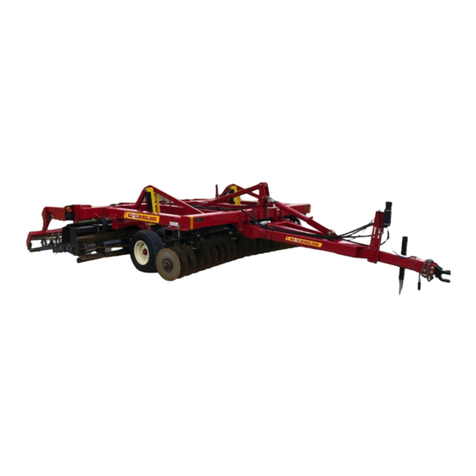
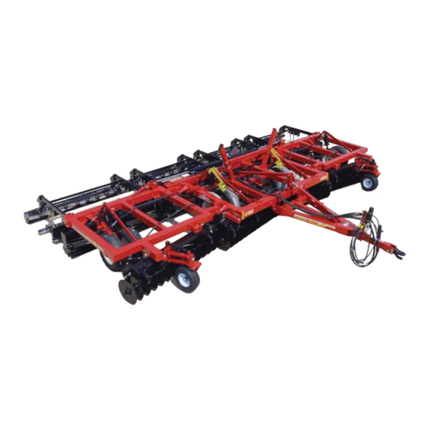
The Finalizer is available in a 24’, 29’ and 32’ folding
frames. The horsepower required to pull the Finalizer is
approximately 8-9 hp per foot of width.
Contact Information
If you have questions not answered in this manual, require
additional copies, or the manual is damaged, please
contact your local dealer or:
McFarlane Mfg. Co., Inc.
1330 Dallas Street
P.O. Box 100
Sauk City, WI 53583
Phone: (608) 643-3322
Toll Free: (888) 627-8569
Fax: (608) 643-3976
E-mail: [email protected]
Web: www.mcfarlaneag.com
Safety
General
Safety of the operator and bystanders is one of the main
concerns in designing and developing a new piece of
equipment. Designers and manufacturers build in as
many safety features as possible. However, every year
many accidents occur which could have been avoided by
a few seconds of thought and a more careful approach to
handling the equipment.
Most work related accidents are caused by failure to
observe basic safety rules or precautions. An accident
can often be avoided by recognizing potentially hazardous
situations before an accident occurs. As you assemble,
operate, tow, or maintain the Finalizer (unit), you must
be alert to potential hazards. You should also have
the necessary training, skills, and tools to perform any
assembly or maintenance procedures.
Improper operation and maintenance of this unit could
result in a dangerous situation that could cause injury or
death.
WARNING
Do not use or tow the unit until you read and
understand the information contained in this
manual.
Safety precautions and warnings are provided in
this manual and on the unit. If these hazard
warnings are not heeded, bodily injury or death
could occur to you or to other persons.
McFarlane cannot anticipate every possible circumstance
that might involve a potential hazard. The warnings in this
manual and on the product are, therefore, not all-inclusive.
If a method of operation not specically recommended by
us is used, you must satisfy yourself that it is safe for you
and for others. You should also ensure that the unit will not
be damaged or be made unsafe by the methods that you
choose.
The information, specications, and illustrations in this
manual are based on the information that was available at
the time this material was written and can change at any
time.
3Finalizer 6000 Series Mcfarlaneag.com 888-627-8569

Safety Alert Symbols
This is the safety alert symbol. It is used to alert
you to potential personal injury hazards. Obey all
safety messages that follow this symbol to avoid
possible injury or death.
This manual contains DANGERS, SAFETY
INSTRUCTIONS, CAUTIONS, IMPORTANT NOTICES,
and NOTES which must be followed to prevent the
possibility of improper service, damage to the equipment,
personal injury, or death. The following key words call the
readers attention to potential hazards.
Hazards are identied by the “Safety Alert Symbol” and
followed by a signal word such as “DANGER”, “WARNING”,
or “CAUTION”.
DANGER
Indicates an imminently hazardous situation which, if
not avoided, will result in death or serious injury. This
signal word is limited to the most extreme situations.
WARNING
Indicates a potentially hazardous situation which, if not
avoided, could result in death or serious injury.
CAUTION
Indicates a potentially hazardous situation which, if not
avoided, may result in minor or moderate injury.
NOTICE
Indicates that equipment or property damage can result if
instructions are not followed.
SAFETY
INSTRUCTIONS
Safety instructions (or equivalent) signs indicate
specicsafety-relatedinstructionsorprocedures.
NOTE: Contains additional information important to a
procedure.
4Finalizer 6000 Series Mcfarlaneag.com 888-627-8569

Safety Icons Nomenclature
This manual and the equipment
has numerous safety icons. These
safety icons provide important
operating instructions which alert
you to potential personal injury
hazards.
Personal Protection/Important
Information
Read the manual
Maintenance procedure
Crush hazard
Eye protection
Hand protection
Head protection
Hearing protection
Inspect equipment
OEM
OEM
OEM parts only
Place in neutral
Protective shoes
Remove key
N
I
NG
AR
Damaged hazard label
Set parking brake
Slow vehicle placard
STOP
Stop engine
Support stand usage
Use proper tools
Visually inspect
Prohibited Actions
Do not alter or modify
Do not leave out tools
Do not weld
No alcohol
No children
No drugs
No open flame
No passengers
No riders
No smoking
Hazard Avoidance
Block wheels
Crushing hazard (body)
Crush hazard (foot)
Crush hazard (rolling over)
Defective or broken part
Entanglement hazard
Explosive separation hazard
Falling hazard
Fire hazard
High-pressure fluid hazard
Hose damage
Hot surface
Maintain safe distance
Overturn hazard
Pinch point hazard
Pressure alert / check
pressure
Projectile hazard
Safety alert symbol
Sharp object hazard
Slipping injury
Tripping injury
0
Zero pressure
5Finalizer 6000 Series Mcfarlaneag.com 888-627-8569

General Operating Safety
WARNING
Read And Understand Manual
To prevent personal injury or even death, be sure
you read and understand all of the instructions in
this manual and other related OEM equipment
manuals! This equipment is dangerous to children and
persons unfamiliar with its operation. The operator
should be a responsible adult familiar with farm
machinery and trained in this equipment’s operations.
Do not allow persons to operate or assemble this unit
until they have read this manual and have developed a
thorough understanding of the safety precautions and
how it works.
Thisunitwasdesignedforaspecicapplication;DO
NOT modify or use this unit for any application other
than which it was designed.
Units operated improperly or by untrained personnel
can be dangerous!
N
I
NG
AR Hazard And Information Signs
Replaceanymissingorhard-to-readdecals.
Decal placement and part numbers can be found
in the Nomenclature section of this manual.
Damaged Parts Hazard
Do not use this unit if it is in need of repair. If
you believe the unit has a defect which could
cause damage, injury, or death, you should
immediately stop using the unit.
Fall Hazard
Do not use the unit as a work platform. Do
not stand on top of the unit at any time. Do
not ride on the unit or allow others to ride on it.
Entanglement Hazard
Donotwearloosettingclothingwhichmay
become entangled in moving parts.
STOP
Crush Hazard (Rolling Over)
When disconnecting the unit or leaving the
operator’s seat:
1. Stop the tractor or towing vehicle.
2. Shutotheengineandremovetheignitionkey.
3. Set the brakes.
4. Make sure wheel cylinder transport locks are
attached.
5. Relievehydraulicuidpressure.
6. If parking the unit, make sure jack stand is
lowered and retaining pin is installed.
Injury Hazard
Do not permit children to play on or around the
stored unit.
WARNING
Impaired Operator Hazard
Do not attempt to operate this unit under
theinuenceofdrugsoralcohol.Review
the safety instructions with all users annually.
Personal Protection Equipment
When working around or operating this unit, wear
appropriate personal protective equipment. This list
includes but is not limited to:
• A hard hat
• Protective shoes with slip resistant soles
• Protective goggles, glasses, or face shield
• Heavy gloves and protective clothing
Safe Distance
Keep all bystanders, especially children, away
from the unit while in operation.
SAFETY
INSTRUCTIONS
To prevent injury, use a tractor equipped with a
Roll Over Protective System (ROPS).
Visually Inspect
Visually inspect the unit for any loose bolts,
worn parts, or cracked welds, and make
necessary repairs before using the unit.
Towing Safety
For towing safety information, refer to the Towing section.
Operation Safety
For operating safety information, refer to the Operation
section.
Assembly Safety
For assembly safety information, refer to the separate
Assembly manual.
Maintenance Safety
For maintenance safety information, refer to the
Maintenance section.
6Finalizer 6000 Series Mcfarlaneag.com 888-627-8569
Component Nomenclature
Component Locations
1
2
3
4
The Finalizer is comprised of four components: (1)
Cobra disk gangs, (2) shanks with Talon™sweep, (3)
Conditioning option (Conditioning Reel or Spur-Till) and
(4) Finishing conguration (3-bar harrow with single rolling
basket or 5-bar harrow).
7Finalizer 6000 Series Mcfarlaneag.com 888-627-8569
Specications(sameforallconditioningoptionsandnishingcongurations)
Hydraulic Requirements
This unit operates with hydraulic pressures of 2500 to 3000
psi (170 to 205 bars).
Horsepower Range
FN-6024-ST3RB — 240 to 330
FN-6029-ST3RB — 280 to 400
FN-6032-ST3RB — 320 to 445
Tillage Depths
Sweep depth up to 5” (12.7 cm)
Tongue Weight
Tongue weight of the unit is approximately 700 lbs. (318 kgs)
Overall Weight (GVWR)
FN-6024-ST3RB — 17,140
FN-6029-ST3RB — 19,757
FN-6032-ST3RB — 20,864
Transport Width
FN-6024-ST3RB — 15’4”
FN-6029-ST3RB — 15’4”
FN-6032-ST3RB — 15’4”
Transport Height
FN-6024-ST3RB — 9’11”
FN-6029-ST3RB — 12’3”
FN-6032-ST3RB — 13’6”
Working Tillage Width (Cut Width)
FN-6024-ST3RB — 24’3”
FN-6029-ST3RB — 28’9”
FN-6032-ST3RB — 31’9”
FieldCapacity(acre/hr@6-8mph)
FN-6024-ST3RB — 15-20
FN-6029-ST3RB — 18-24
FN-6032-ST3RB — 20-26
Towing Speed
Towing speeds should not exceed 20 mph (32 kph)
Field operating speeds should be 6-8 mph (9-13 kph).
8Finalizer 6000 Series Mcfarlaneag.com 888-627-8569
Instructions for Display of Hazard and
Informational Signs
• It is the responsibility of the customer to know the
lighting and marking requirements of the local highway
authorities and to install and maintain the equipment
to provide compliance with the regulations. Add extra
lights when transporting at night or during periods of
limited visibility.
• Keep safety signs clean and legible at all times.
Replace safety signs that are missing or have become
illegible.
• Do not paint over, remove, or deface any safety signs
or warning decals on your equipment. Observe all
safety signs and practice the instructions on them.
• Replacement parts that display a safety sign should
display the same sign.
• Make sure the hazard warning labels or other
information decals are legible and attached to the unit
before use.
• Safety signs are available from your Distributor, Dealer
Parts Department, or the factory.
NOTICE
Tractor must be in
constant flow mode.
Do not exceed 250 PSI
during field operation.
14671
1 Turn = 1/2”
Deeper
9Finalizer 6000 Series Mcfarlaneag.com 888-627-8569
1 Turn = 1/2”
Deeper
WARNING
Cancer and Reproductive Harm
www.P65Warnings.ca.gov
14039
14051
DC-306
DC-231
NOTICE
Tractor must be in
constant flow mode.
Do not exceed 250 PSI
during field operation.
14671
Assembly
Refer to the separate Finalizer Assembly manual for
complete assembly instructions.
15461
14050
10Finalizer 6000 Series Mcfarlaneag.com 888-627-8569
NOTICE
Tractor must be in
constant flow mode.
Do not exceed 250 PSI
during field operation.
14671
Assembly
Refer to the separate Finalizer Assembly manual for
complete assembly instructions.
Towing
General Safety
SAFETY
INSTRUCTIONS
Towing the Finalizer requires care! Both the unit
and tow vehicle must be in good working
condition. Securely attach to towing unit. Use a
high strength, appropriately sized hitch pin with a
mechanical retainer and attach safety chain.
Make sure the hitch and coupling on the towing
vehicle are rated equal to, or greater than, the
unit’s “gross vehicle weight rating” (GVWR).
Refertothespecicationsection.
Make sure the safety chain is securely fastened
to the tow vehicle.
Checkthetiresfortreadwear,inationpressure,
and overall condition.
Inspect the hitch and coupling for wear or
damage. DO NOT tow the unit using a defective
hitch or coupling!
Make sure directional, brake, and running lights
are connected and working properly.
Make sure the lug nuts holding the wheels are
tight(torquetospecications)andthatnoneare
missing.
When towing the unit on the highway, make sure
the “Slow Moving Vehicle” placard is clearly
visible.
Do not allow anyone to stand between the tongue
or hitch and the towing vehicle when backing up
to the equipment.
Make sure that the area is clear of children,
animals, and other obstacles before using.
15438
14571
11Finalizer 6000 Series Mcfarlaneag.com 888-627-8569
Safety Chain
SAFETY
INSTRUCTIONS
• If the unit will be transported on a public highway, the
safety chain must be attached to the tow vehicle.
• Always follow state and local regulations
regarding a safety chain when towing farm
equipment on a public highway.
• Be sure to check with local law enforcement
agencies for any local regulations or restrictions.
• Do not use any device other than the safety chain that
was supplied with the unit. Only a safety chain (not an
elastic or nylon/plastic tow strap) should be used to
retain the connection between the tow vehicle and the
unit in the event of separation of the primary attaching
system.
Bystanders
SAFETY
INSTRUCTIONS
• Beware of physical surroundings and especially
bystanders, particularly children, before moving
the unit! This is particularly important with higher
noise levels and quiet cabs, as you may not
hear people shouting.
• NO PASSENGERS ALLOWED - Do not
carry passengers anywhere on or in the
tractor, except as required for operation.
• Do not allow anyone to ride on the unit while it
is moving.
Towing and Maximum Towing Speed
SAFETY
INSTRUCTIONS
• Operate the towing vehicle from the operator’s seat
only.
• Do not exceed a towing speed of more than 20 mph
(32KPH) on a public roadway.
• Remember, tires supplied by the manufacturer
are designed to operate LESS THAN 20 mph. Do
not exceed or tire failure may occur.
Highway and Transport Operations
SAFETY
INSTRUCTIONS
• Make sure the wheel cylinder transport locks are
installed, the wing lock pins are in place, and the jack
stand is in its storage position before transporting the
unit.
SAFETY
INSTRUCTIONS
• Never use independent braking with unit in tow as loss
of control and/or upset of unit may result.
• Always drive at a safe speed relative to local conditions
and ensure that your speed is low enough for an
emergency stop to be safe and secure. Keep speed to
a minimum.
• Reduce speed prior to turns to avoid the risk of
overturning.
• Avoid sudden uphill turns on steep slopes.
• Always keep the tractor or towing vehicle in gear to
provide engine braking when going downhill. Do not
coast.
• Use approved accessory lighting or ags and
necessary warning devices to protect operators of
other vehicles on the highway during daylight and
nighttime transport. Various safety lights and devices
are available from your dealer.
• The use of ashing amber lights is acceptable in most
localities. However, some localities prohibit their use.
Local laws should be checked for all highway lighting
and marking requirements.
• When driving the tractor and equipment on the road or
highway, use ashing amber warning lights and a slow
moving vehicle (SMV) identication emblem.
• Be a safe and courteous driver. Always yield to
oncoming trac in all situations, including narrow
bridges, intersections, etc. Plan your route to avoid
heavy trac.
• Be observant of bridge loading ratings. Do not cross
bridges rated lower than the gross weight at which you
are operating.
• Watch for obstructions overhead and to the side while
transporting.
• Always operate equipment in a position to provide
maximum visibility at all times. Make allowances for
increased length and weight of the equipment when
making turns, stopping, etc.
12Finalizer 6000 Series Mcfarlaneag.com 888-627-8569
Pre-towingChecklist
1. Before towing, make sure the maintenance on the
tractor and the unit are current. This is very important
because towing puts additional stress on the tow
vehicle.
2. Check and correct the tire pressures on the tow
vehicle and the unit. Refer to the Tire and Lug Torque
specication chart in the manual.
3. Make sure the hitch, coupler, and any other equipment
that connects the unit and the tow vehicle are properly
secured and adjusted. Always inspect the hitch and
tongue for cracks when hooking up.
WARNING
Substandard Parts Hazard
If towing the unit with a draw bar, use only an
OEMcertied,hardeneddrawbarpinwitha
retainer clip. Do not use homemade pins, bolts, or any
other type of retaining device. Always install the
retainer clip, making sure the hitch and unit are
securely fastened to the tow vehicle.
Using a pin not intended for this type of towing, can
result in unexpected separation of the unit from the
tow vehicle resulting in equipment damage and
personal injury.
4. Verify the appropriate Category 3 or Category 4 hitch is
securely installed.
WARNING
Unexpected Separation Hazard
If the safety chains do not have a current
certicationtag,donotusetheunituntil
properlycertiedchainsareinstalled.Substandard
safety chains could allow the unit to separate from the
tow vehicle resulting in equipment damage and
personal injury.
5. Attach the safety chain from the unit to the tow vehicle.
The safety chain should be long enough for tight turns.
Don’t allow the chain to drag on the pavement because
it will wear the chain links causing an unsafe condition.
6. Make sure the electrical wiring harness for the running
lights and taillights is properly connected and not
touching the road, but loose enough to make turns
without disconnecting or damaging the wires.
7. Have an observer conrm all running lights, brake lights,
turn signals, and hazard lights are working on both the
tow vehicle and the unit.
8. Verify the brakes on the tow vehicle are operating
correctly.
9. Make sure transport locks are securely in place around
the cylinder rods.
10. Make sure the jack stand is raised and locked in the
storage position.
11. Make sure the wing lock pins are in place.
12. Check mirrors of the tow vehicle to make sure you have
good visibility.
13. Check routes and restrictions on bridges and tunnels.
13Finalizer 6000 Series Mcfarlaneag.com 888-627-8569

Safety
SAFETY
INSTRUCTIONS
Make sure that anyone who will be operating the unit or
working on or around the unit reads and understands
all the operating, maintenance, and safety information
in the operator’s manual and other related OEM
equipment manuals before using or towing the unit.
Prior to Connecting Unit
Make sure the unit is resting on the ground or the
transport locks are securely installed over the wheel
cylinder rods before attaching the unit to the tractor.
SAFETY
INSTRUCTIONS
If the unit is not resting on the ground, make
surewheelchocksaresecurelyttedonboth
sides of each wheel.
WARNING
Crush Hazard
The tongue weight of the unit is
approximately700lbs.(318kgs.).Use
care when lifting or attaching the unit to the tractor.
Never place any part of your body under the tongue or
hitch assembly.
Hydraulic Pressure
This unit operates with hydraulic pressures of
2500 to 3000 psi (170 to 205 bars).
High-Pressure Fluids
1. Check or tighten all connections BEFORE
pressurizing system.
0
2. Release all pressure before removing hoses
and/or valves by:
a. Stopping engine.
b. Holdinghydrauliccontrolleversinoator
neutral position.
3. DO NOT use your bare hand to check for
potential leaks. Always use a board or
cardboard when checking for a leak.
Escapinghydraulicuidunderpressure,evena
pinhole size leak, can penetrate body tissue, causing
seriousinjuryandpossibledeath.Ifuidisinjected
into your skin, it must be treated immediately by a
doctor familiar with this type of injury.
Tow Chain
A certied tow chain is supplied with each unit. This chain
must be attached to the tractor during towing or operation
of the unit.
SAFETY
INSTRUCTIONS
Inspect the chain annually for wear or damage.
OEM
OEM
Do not replace the chain with anything other
thananOEMcertiedreplacement.
14Finalizer 6000 Series Mcfarlaneag.com 888-627-8569

Connecting to the Tractor
1. Raise the jack stand and connect the tongue to the
tractor. The tongue weight of the unit is approximately
700 lbs. (318 kgs).
Note: If a drawbar pin is used, it should be an OEM
certied pin and retainer clip. On category 3 pintle
hitches use a 1-1/2” (38 mm) pin. On category 3
clevis hitch use a 1-1/4” (32 mm) pin. On category 4
articulating ball pintle hitch use a 2” (51 mm) pin.
WARNING
Unexpected Separation Hazard
If towing the unit with a drawbar, use only a
certied,hardeneddrawbarpinwitharetainer
clip. Do not use homemade pins, bolts, or any other
type of retaining device. Always install the retainer clip,
making sure the hitch and unit are securely fastened to
the tow vehicle.
Using a pin not intended for this type of towing can
result in unexpected separation of the unit from the
tow vehicle, resulting in equipment damage and
personal injury.
2. Connect the hitch of the unit to the tractor. Attach the
tow chain to the tractor’s draw bar cage.
Note: When connected, make sure the retaining plate
securely locks the chain link in place.
3. Remove the jack stand and place it in its storage
position inside the frame, as shown.
15Finalizer 6000 Series Mcfarlaneag.com 888-627-8569

1. Remove the hydraulic hoses from their storage position.
2. Connect the hydraulic hoses to the tractor.
Note: The most commonly used function of the unit is the
“main lift” cylinders, which raises and lowers the
wheels. Connect the hydraulic hoses for this function
into the port (control lever) used most commonly.
3. Disconnect the electrical connection for the rear lights
from the storage socket.
a. Rotate the plug.
16Finalizer 6000 Series Mcfarlaneag.com 888-627-8569

17Finalizer 6000 Series Mcfarlaneag.com 888-627-8569
b. Push the plug upward and slightly rotate it again to
release it from the socket.
c. Pull the plug downward.
d. Connect the plug into the tractor’s electrical socket.
1. Make sure all the hydraulic cylinders are functioning
properly.
2. Make sure the amber and red indicator lights are
working properly.
3. Move the unit to the desired location and position it for
operation following the towing recommendation provided
in this manual and/or any other local, State, or Federal
regulations that may apply.

18Finalizer 6000 Series Mcfarlaneag.com 888-627-8569
Operation
Safety
WARNING
To prevent serious injury or death, follow these safety
instructions
Entanglement Hazard
Keep hands and clothing clear of moving parts.
Crush Hazard (Rolling Over)
Do not clean, lubricate, or make adjustments
while the unit is moving.
STOP
Crush Hazard (Rolling Over)
When making adjustments to the
unit or leaving the operator’s seat:
1. Stop the tractor.
2. Shutotheengineandremovetheignitionkey.
3. Set the brakes.
Overturn Hazard
Pick the levelest possible route when
transportingacrosselds.Avoidtheedgesof
ditches or gullies and steep hillsides.
Safe Distance
Keep all bystanders, pets, and livestock clear of
the work area, particularly when raising or
lowering the unit.
SAFETY
INSTRUCTIONS
Periodically clear the unit of brush, twigs, or
other materials to prevent buildup of dry,
combustible materials.
NOTICE
DO NOT turn while the unit is in the ground.
DO NOT operate the unit in frozen ground.
Initial Setup
The McFarlane Finalizer is a tool that is designed to
handle a wide variety of eld conditions. It has many
adjustments that can be made to change the performance
of each component on the unit as well as its overall
performance. Achieving the best results over the widest
range of circumstances can be accomplished by making
adjustments to match the eld conditions.
Note: It is important to make one adjustment at a time in
order to see the results of each change. If several
adjustments are made at the same time, the
operation of the machine can change dramatically,
creating confusion and frustration.
WARNING
Pinch Point Hazard
Donotplacehandsorngersbetweenmoving
and/or stationary parts. The weight of the unit
will easily cause serious bodily injury.
Sharp Object Hazard
Do not place any part of your body under the
disk gang during the adjustment process.
Severe injury will occur if a person contacts
or falls under the disk gang.
1. If equipped with wings, remove the wing fold lock pins
and bridge pin and store them on the wing lock bracket.

19Finalizer 6000 Series Mcfarlaneag.com 888-627-8569
2. If necessary, raise the unit and release the transport
locks from both wheel cylinders.
a. Remove the retainer clip.
b. Place the locks in their storage location on the wing
side lock bracket and fasten with the retaining clip.
Storage
Location
Lock
3. Move the unit to a level and smooth area.
4. Raise the disk gangs and conditioning option
(Conditioning Reel or Spur-Till) to their maximum height.
5. Lower the unit until the sweeps are just touching the
ground.
Machine Leveling
Raise the locking mechanism from the turnbuckle.
Use the wrench (stored behind the hitch) to make the
adjustment.
Note: As viewed from the front of the unit, turning the
turnbuckle counterclockwise will raise the hitch end
and lower the back end.
a. Check the frame for levelness by verifying that all
sweeps are contacting the ground.
b. Once the unit is level from front to back, place the
locking mechanism over the turnbuckle.

20Finalizer 6000 Series Mcfarlaneag.com 888-627-8569
Leveling Wing Frames
Level the wing frames. This prevents the sweeps from
gouging and/or ridging. It also ensures a consistent
operating depth across the width of the unit.
a. Loosen jam nut and turn the adjusting nuts to
raise or lower the wings. Repeat on other wing.
b. Run the unit in the ground a short distance and
check the wing levelness and repeat adjustment if
necessary.
1. Lower the unit into the ground and pull forward,
stopping to check that all sweep are tilling to the
same depth by brushing away the loosened soil.
WARNING
STOP P
Beforeleavingthetractor,shutotheengine,setthe
parking brake, and remove the ignition key.
Raise
Lower
Sweep Depth Adjustment
1. Adjust the depth of the sweeps using the single point
depth stop at the front of the unit.
a. Lower the sweeps to the desired depth.
b. Turn the stop crank (depth control) to fully depress
the pin on the hydraulic stop valve.
c. Pull the unit through the eld and stop the unit
without raising it.
d. Check the depth of the sweeps and adjust the stop
crank accordingly.
e. If the sweeps need to be reset, turn the stop crank
accordingly; two full turns of the crank equals 1 inch
of depth adjustment.
1 Turn = 1/2”
Deeper
Note: Since the wheels position the height of the entire
frame of the unit, the depth setting of the other
components also needs to be checked and possibly
readjusted any time the sweep depth is changed.
Disk Depth Adjustment
1. Pull the unit through the eld with the sweeps in the
ground and then lower the disk gangs until they start
tilling the soil, approximately 3” deep. The disks are
primarily for slicing residue and weeds. In uneven,
tilled soil, it may be necessary to run the disk gangs
deeper to improve soil leveling. In hard ground, run the
disks more shallow to prevent the front sweeps from
being lifted out of the ground.
WARNING
STOP P
Beforeleavingthetractor,shutotheengine,setthe
parking brakes, and remove the ignition key.
Table of contents
Other McFarlane Farm Equipment manuals

McFarlane
McFarlane QUADRA-TILL 200 Series Guide

McFarlane
McFarlane RD-4000 Series Troubleshooting guide

McFarlane
McFarlane Universal Tillage COBRA 4200 Series Guide

McFarlane
McFarlane HDL-1000 Series Installation and maintenance instructions

McFarlane
McFarlane Reel Disk 4100 Series Guide

McFarlane
McFarlane HDL-100-8 Series Manual

McFarlane
McFarlane INCITE 5100 Series User manual

McFarlane
McFarlane HDL-1100 Series Installation and maintenance instructions