What is Z-Wave?
Z-Wave is the international wireless protocol for communication in the Smart Home. This
device is suited for use in the region mentioned in the Quickstart section.
Z-Wave ensures a reliable communication by
reconfirming every message (two-way
comm nication) and every mains powered
node can act as a repeater for other nodes
(meshed network) in case the receiver is not
in direct wireless range of the transmitter.
This device and every other certified Z-Wave
device can be sed together with any other
certified Z-Wave device regardless of brand
and origin as long as both are suited for the same frequency range.
If a device supports sec re comm nication it will communicate with other devices secure as
long as this device provides the same or a higher level of security. Otherwise it will
automatically turn into a lower level of security to maintain backward compatibility.
For more information about Z-Wave technology, devices, white papers etc. please refer to
www.z-wave.info.
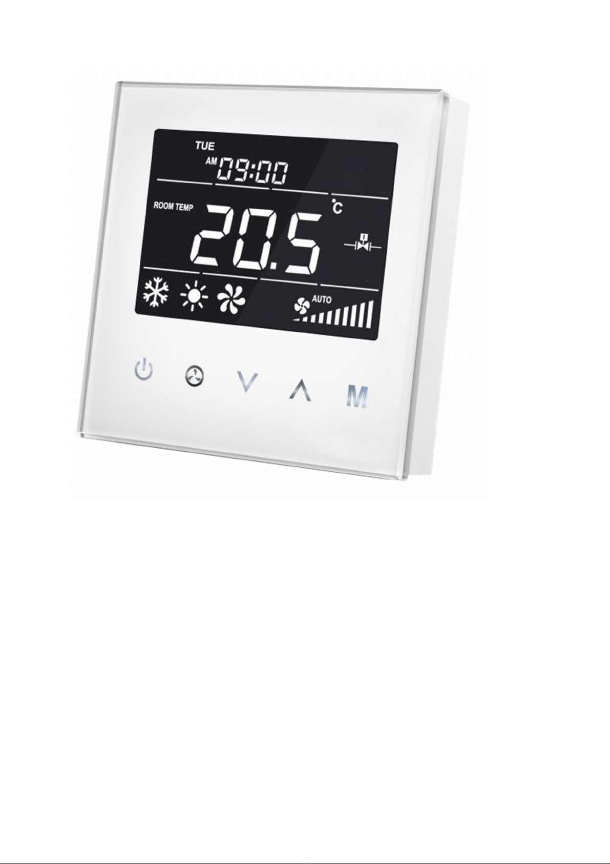
Prod ct Description
MCOHome Fan Coil Thermostat is a Z-Wave enabled device for indoor temperature control.
It is mainly applied to a 2-pipe Fan coil system. It can read room temperature and local time,
and automatically control fan speed based on the temperature difference. The device is of high
reliability and practicability. This product can be included and operated in any Z-Wave
network with other Z-Wave certified devices from any other manufacturers.
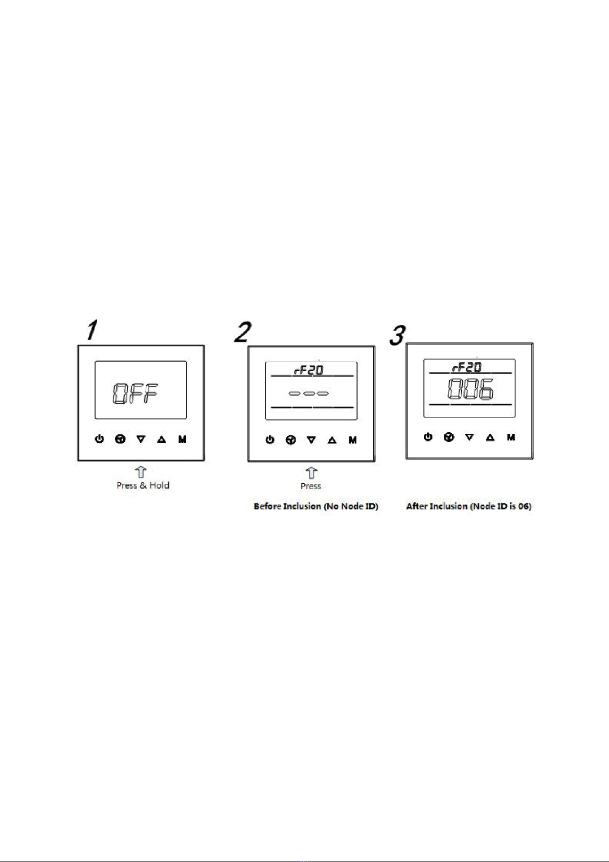
Prepare for Installation / Reset
Please read the user manual before installing the product.
In order to include (add) a Z-Wave device to a network it m st be in factory defa lt state.
Please make sure to reset the device into factory default. ou can do this by performing an
Exclusion operation as described below in the manual. Every Z-Wave controller is able to
perform this operation however it is recommended to use the primary controller of the
previous network to make sure the very device is excluded properly from this network.
Safety Warning for Mains Powered Devices
ATTENTION: only authorized technicians under consideration of the country-specific
installation guidelines/norms may do works with mains power. Prior to the assembly of the
product, the voltage network has to be switched off and ensured against re-switching.
Installation
Location: