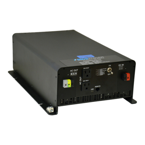
MDS Power FC500-400 User manual

CONTENTS
Source Control Document
Wiring Diagram
Terminations
Outline Drawing
Photograph
Instructions Operation and Troubleshooting
Safety Considerations
Maintenance & Service

®
p
p
p
J
i
°
r

Wiring Diagram
FC1000-400

TERMINATIONS
FC1000-400
Input

OUTLINE DRAWING
FC1000-400
Drawn by
BZ/ys Date
June 29, 2022
Updated by
TS Drawing Number
ODR 30U5 A100A
Approved by
TS

PHOTOGRAPHS
FC1000-400

FC1000-400
INSTALLATION OPERATION AND TROUBLESHOOTING
1. Inspect unit for visible transit damage. Should there be any cause for concern, please contact
factory before returning unit. No returns will be accepted without a Return Authorization
2. Check that the power supply input matches to the applicable input source.
3. Connect input and output according to the labels on the unit.
4. Verify that the proper wire gauge is used to minimize the line loss. (Guidelines for wire size
applications are included.)
5. The output voltages and current limits are factory set according to the specifications. Should it
be necessary to re-adjust any of these parameters, please consult with Engineering
6. This unit is fan cooled. Ensure that minimum 4” space left at the intake and exhaust openings.
SAFETY CONSIDERATIONS
1. The unit has hazardous voltages at any part of the power supply circuitry also on the terminal
blocks. Therefore the unit can be operated by qualified and instructed personnel only. Avoid
touching any component or parts inside the unit. Wait a minimum of 30 seconds after
removing the input power before doing any operation on the power supply.
2. The chassis of the unit is connected internally to the GND terminal. One ground terminal is
provided on the terminal block.(Terminal #3) and the M5 bolt on the chassis. It is sufficient to
wire up one of these terminals only.
3. Use the proper screw sizes for mounting.
4. This unit is electronically protected. If the system doesn’t work properly, we recommend that
the operator do not replace any of the internal fuses on the power modules or attempt repair.
Return the power supply for servicing.
5. Repairs should only be performed by qualified service personnel.

RECOMMENDED WIRE SIZES
The following values are to be used for guidelines only. For longer wire lengths, larger gauge may be
needed to minimize line losses.
100 to 150Amps
0
53
150 to 300Amps
000
85

MAINTENANCE
Preventative maintenance on this product is minimal. Under normal circumstances, the only
maintenance required is a regular visual inspection of the unit to check for any signs of dust, dirt,
corrosion or other damage.
Electronic systems that are used in harsh environments should be inspected more frequently as well as
cleaned if dusty, or dirty. Accumulated dust may block airflow and impede cooling which can cause
overheating of the unit. These units should also be checked thoroughly for any loose hardware or
damaged wiring caused by excessive shock and vibration.
.
WARRANTY AND SERVICE
1. Standard warranty is for 2 years subject to application within good Engineering practice.
Contamination related failures and shipping cost excluded
2. Should servicing be required please contact service manager for return authorization.
MDS Power Inc.
© Copyright 2022
Specifications subject to change
mdspower.com
800.931.4919
514.369.4919
This manual suits for next models
3
Other MDS Power Inverter manuals
Popular Inverter manuals by other brands

Porta Source
Porta Source IG800W Operator's manual

Ingersoll-Rand
Ingersoll-Rand Nirvana 5.5 troubleshooting guide

Mitsubishi Electric
Mitsubishi Electric 800 Series instruction manual

Westerbeke
Westerbeke 5.5 BCD-614 specification

GE
GE HOME NERATOR 7000 WATT Operator's manual

Daikin
Daikin FTXG-C Technical data