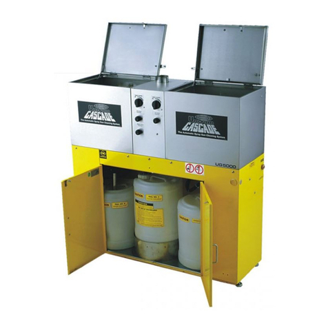
MDT CASTLE 2415-UW User manual

SERVICE
MANUAL
M
X
2
Castle
2415-UW
Ultrasonic
Cleaner
MDT
BIOLOGIC
COMPANY
1777
East
Henrietta
Road
PO
Box
23077
Rochester,
New
York
14692-3077
USA
)
MDT
Technology
for
Life
350593
Rev,
A

SERVICE
MANUAL
350593
Rev.
A
(3/14/96)
New
Release
Related
Publications:
Owner
&
Operators
Manual
350490
Parts
Catalog
350594
DESCRIPTION
OF
SYMBOLS
&
NOTES
IN
MANUAL
The
following
symbols
with
related
notes
appear
in
this
manual.
“Warning”
notes
alert
the
user
to
the
possibility
of
personal
injury.
“Caution”
notes
alert
the
user
to
the
possibility
of
damage
to
the
equipment.
“Notes”
alert
the
user
to
pertinent
facts
and
conditions.
NOTE
>
NOTE
This
manual
contains
proprietary
information
of
MDT
Corporation.
It
shall
>
not
be
reproduced
in
whole
or
in
part
without
the
written
permission
of
MDT.
®MDT
and
Castle
are
tegistered
trademarks.
Copyright
©
1996
by
MDT
Corporation
ii
350593

Table
of
Contents
1.
General
Information
Service
Features...
-<
nen
nens
1-2
Safety
Features
............
e
1-2
Technical
Data.
.
ee
1-3
Electrical
.........................,..,....,
1-3
Services
0.0008.
1-3
Weight.............
6.8.8
1-3
Ultrasonics
.
2. 2.
ee
1-3
Dimensions
.
....................,..,........
1-3
Ultrasonics
System
......................
이 이
이이
이의
14
Generators
1G,
2G
..................,,,...,....
1-4
Transducers.................
κ
εκ
ο
εν
κ
εν
νε
κ
νο
1-4
Timer1TMR
し
し し
ーー
14
Tank/lid
Components
........................
.....
1-4
Неее
еее
еее
1-4
tidGasket..................................
1-4
Work
Tray
Platform
............................
1-4
WokTraV
し
ーー
1-5
Motor
....................,.,........,....
1-5
Torque
Limiter.
..................,.....,.....
1-5
Brake
.............
reen
1-5
DiveAMmM
................
1-5
WaterDetergert
FlPot
し
し
ο
τον
1-5
OverlowPot
...............................
1-5
Drain
Screen/Drain
............................
1-5
LowLevelSensorPot
し
し
κ ον ον
νυν
1-5
HighLevelSensorPot
..........................
1-5
Control
Components
.
.
2.
. 2
2 2
2
rene
1~6
Controi
Panel
Cover.
....................,.....,
1-6
Power
1PB
....................,.......,...
1-6
Sop2PB
...............
1-6
Lid
3PB
......................,....,,.,...
1-6
Degas
6PB
.......................,.........
1-6
Fil4PB
0...
ee
ee
1-6
Ὀταίη
ΘΡΒ
es
1-7
Timer
ITMR
し
し
22
2222
이
이 이
이
이 이
이 키
이
워
이의
의
이의
이
이이
이
이
의 의
1-7
Alarm
еее
еее
1-7
Toe
SwitchTSW
ο
νο
ο
νε
νο
νε
ο
εκ
ενω
ενος
εν ων
ους
1-7
Reference—Push
Buttons
.
................,....,,
1-7
350593

Table
of
Contents
(cont'd)
Cabinet
Components
..........,......,............
1-8
Daor..............,......,...............
1-8
DoorinterlockSwitchDRSW.......................
1-8
Sonic
Generators
1G,2G
............,.,...........
1-8
Water
Supply
Shutoff
.
................,.........
1-8
DetergeniFlowVave...........................
1-8
Detergent
Supply
TUDE
..........................
1-8
Detergent
Supply
.
............,......,........
1-8
2.
Theory
of
Operation
Introduction
...............,...................
2-1
O&ONotes
..................
2-1
Ultrasonic
Cleaning
. . .
2
2.
2.
2 2
2
이이
이 이
이이
이이
이이
이 이 이 이 이
이이,
,
2-1
O&ONotes
.
2.
.
2 2
ee
2-1
Ultrasonic
Sequences
. .
ener
rvee
2-2
Main
Components
.
.........,.,.............,....
2-3
Motorized
Lid
and
Platform
..........................
2-4
O&O
Notes
.............,.....,.,...........
2-4
Operation
.........................
ee
2-44
MainComponents.............................
2-4
Drain.
ee
2-5
Sequence
.
ο
νε
κ
ων
κ
ων
ενω
ων
νο
νο
κι
2-5
Main
Components.
2.
2 . 2
ns
2-5
ーー
2-5
Seguence
.................
2-5
Main
Components
........,......,............
2-5
Level
&
Temperature
Control
.........................
2-6
Level
Control
.
.....................,.........
2-6
Temperature
Control
...............,........,..
2-7
Control
System
...............................,
2-8
MainComponents.............................
2-8
3.
Service
Data
..........................
3-1
4.
Troubleshooting
Troubleshooting
Chart.
.............,..........,...
4~1
Conditionat
Instructions
............................
44
Emergency
Stop
.............................
4-4
Manualiy
OpeningaClosedlid......................
44
iv
350593

Table
of
Contents
(cont'd)
5.
Adjustments
and
Calibration
interiock
Bypass
(Power
with
Door
Open)
..................
5-1
Detergent
FowRate
.............................
5-2
DetergeniFlowVave...........................
5-2
Detergent
Flow
Rate
..........,.................
5-2
Setting
the
DetergentFilowRate
.....................
5-2
Aluminum
Foil
Test
. .
............................
5-4
Inspect
and
Test
the
Transducers
.
.....................
54
Fili
and
Heating
Test
.
.............,...,...........
5-6
Timer
eree
5-8
Summary
..
ee
5-8
Setting
the
Timer
(Programming)
.
................,...
5-8
Setting
the
Run
Time
...........................
5-8
Programming
Mode
.
.........................,..
5-8
Setting
the
Range.
............................
5-9
Setting
the
Direction
.
...................,..,.,,
5-9
Setting
the
Timer
Mode
.
.........................
5-10
άν
νο
νε
νε νε
νε
εν νε
νε
νε εν εν
νε
κ
εν εν
ο
εν
νε
νυν
5-11
Lid
Position
.
.........,..,...................
5-11
Adjust
the
Drive
Arm
...........................
5-12
Adjust
the
Limit
Switches
.
ee
5—13
Adjust
the
Torque
Limiter
.
εν
εν
ον
5-14
Motor
enken
ek
een
5-15
Lubrigation
.......,..,............,.........
5-15
Cleaning
.................................
5-15
Brake
e
eee
ere
5-17
Description
.
..............................,
5-17
Maintenance
...............................
5-17
Level
Probes
LLC1,
LLC2.
..........................
5-18
Test
the
Level
Probes
..........................
5-19
6.
Repair
Replace
the
Lid
Gasket
.
...........................
6—1
Manualiy
Openinga€llosedlid.........................
6-2
Removing
the
Control
PaneiCover......................
6-3
Fuses
........
00000
6-4
Controi
Fuses
.
.............................,
6-4
Generator
Fuses
.
.....,......................,
6-4
Фепегаюг5
„еее
еее
инь
6-5
Removethe
ChassIS
. .
2.
2
2
еее
ен
6-5
SolenoildValves................................
6-5
Repair
Parts
for
Solenoids
........................
6-5
Repiace
the
Injector
.
.............................
6-6
350593

Table
of
Contents
(cont'd)
Brake
..............................,......
6-7
Operation
.
............,...................
6-7
Friction
Disc
Replacement
........................
6-7
Solenoid
Replacement
..........................
6-8
Brake
Replacement
.
.
................,.........
6-8
Torque
Selection
.
............................
6-8
Brake
installation
.............................
6-8
Torque
Limiter.
...............,.................
6-9
Thermai
Switches
1TAS,
2TAS
........................
611
Replace
Thermal
Switch
.........................
6-11
Limit
Switches.
............
e
6-11
Heater
HTR
еее
еее
неее»
6-12
Replace
Heater
.
................,.............
6-12
Recommended
Spare
Parts
.....................
+...
6-14
Index
................,,...4444444
444
に
1
Vi
350593

Figure
1-1.
Figure
1-2.
Figure
1-3.
Figure
1-4.
Figure
2-1.
Figure
2-2.
Figure
3—1.
Figure
3-2.
Figure
3-3.
Figure
3-4.
Figure
3-5.
Figure
3-6.
Figure
4-1.
Figure
5-1.
Figure
5-2.
Figure
5-3.
Figure
5-4.
Figure
5-5.
Figure
5-6.
Figure
5-7.
Figure
5-8.
Figure
5-9.
List
of
Figures
2415—UW
UltrasonicCleaner..................
TanklLidComponents
......................
Control
Components
.
.......,...,............
Cabinet
Components
.
.....................
Level
Control
—
Filling
.
.
....................
Level
Control
—
Draining
.
<<
이 이 의 이
의의
Component
Locations
......................
Piping
Components
.......................
Piping
Schematic
........................
Electrical
Schematic
.
......................
Stop
2PB
Positions
.
......................
interlockBypass
....................
vo.
DetergentFlowVave
......................
Detergent
Flow
Percentages...................
Bypass
the
Thermal
Switches
..................
Transducers
and
Thermal
Switches
...............
LCD
Display
&
Controls
.....................
Time
Ranges
.
..........................
Time
Direction
.
.........................
Time
Modes
.....,..........,..,..,.......
Figure
5-10.
Motor
and
Lid
Components
.
...,.....,.....,....
Figure
5-11.
Adjust
the
Drive
Arm
......................
Figure
5—12.
AdjustthelLimit
Switch
.....................
Figure
5-13.
Torguelimiter
.........................
Figure
5-14.
Brake
Wear
Adjustment
....................
Figure
5-15.
Control
Box,
Level
Probes
and
Level
Probe
Control
Board
Figure
6-1.
Figure
6-2.
Figure
6-3.
Figure
6-4.
Figure
6-5.
Figure
6-6.
Figure
6-7.
Figure
6-8.
Figure
6-9.
Manually
Opening
a
Closed
Lid
.................
Remove
Control
Panel
Cover
..................
Generator
Fuses
.
.....,...,..,..,.........
Removing
a
Generator
Chassis
.................
Replace
the
Injector
.
......................
Brake
Components
.
.
............,..,......
Brake
Operator
Asssembly
.
..................
Torque
Limiter
.
.........................
Replace Thermal
Switch
.
,...................
Figure
6-10.
Remove
the
Heat
Shields
...................
Figure
6-11.
Remove
the
Heater
Strip
....................
6-11
6-12
6-13
350593
vii

NOTES
viii
350593

2415-UW
ULTRASONIC
CLEANER
1.
General
information
GENERAL
INFORMATION
The
Castle
2415~-UW
Ultrasonic
Cleaner
cleans
surgi-
cal
instruments
and
similar
hospital
hardware,
using
ultrasonic
energy
in
a
heated
water-detergent
solution.
It
uses
a
motorized
lid
and
work
platform
to
load
and
unload
goods,
fills
the
cleaning
tank
with
hot
water
and
detergent,
controis
the
solution
level,
heats
and
main-
tains
the
solution
temperature,
agitates
the
solution
with
ultrasonic
energy,
times
the
wash
cycle,
and
drains
the
tank
when
required.
To
run
a
cycle,
the
operator
first
sets
the
timer.
He
then
sets
an
instrument
tray
on
the
work
tray
platform.
He
presses
a
button
to
close
the
lid.
The
lid
closes
and
lowers
the
tray
into
the
liquid.
The
cycle
activates
automatically.
When
the
cycle
is
complete,
the
work
tray
platform
automatically
lifts
the
tray
out
of
the
tank
to
where
it
can
easily
be
removed
to
a
rinsing
station.
NOTE
>
While
sonic
cleaning
effectively
cleans
and
polishes
instruments
in
a
way
unmatched
by
other
methods,
it
does
not
replace
the
sterilization
process.
Instruments
cleaned
in
the
ultrasonic
cleaner
still
need
to
be
rinsed
and
sterilized
before
being
put
back
into
use.
This
manual
contains
the
necessary
instructions
for
maintaining,
testing,
adjusting,
and
repairing
the
Castle
2415-UW
Ultrasonic
Cleaner.
For
optimum
perform-
ance
and
unit
life
MDT
recommends
that
only
fully
authorized
personnel
service
your
equipment.
Refer
to
the
warranty.
Unauthorized
repairs
will
void
the
warranty.
Only
a
fully
authorized
service
person
should
attempt
to
service
this
product.
The
circuits
present
high
level
voltage.
improper
testing
or
repair
procedures
could
result
in
injury
to
the
service
per-
son
and
damage
to
the
product.
35059388
FIGURE
1-1.
2415—UW
ULTRASONIC
CLEANER
350593
1-1

241
5-UW
ULTRASONIC
CLEANER
1.
General
information
SERVICE
FEATURES
serviceable
from
the
front
front-access
to
toe
switch,
control
panel
fuses,
and
main
power
box
detergent
flow
control
is
front-accessible
liquid
level
probes,
heater,
thermostats
are
front-ac-
cessible
removable,
hinged
front
access
door
lift-off
side
panels
interlock
bypass
plug-in
relays
in
control
box
modular
sonic
generators
hinged
work
tray
platform
for
access
to
tank
and
strainer
SAFETY
FEATURES
STOP
button
Stops
lid
motion
when
actuated.
Restart
must
be
with
the
LID
button,
not
the
toe
switch.
Motor
Torque
Stops
lid
motion
if
something
is
Limiter
caught
in
the
lid.
Alarm
Sounds
whenever
the
lid
is
moving.
Front
Door
Power
shuts
off
when
front
door
Interlock
is
opened
or
removed,
Fully
extended,
the
front
door
switch
bypasses
this
interlock
for
troubleshooting
and
repair
with
the
door
open.
Tank
&
lid
Insulated
and
sound
dampened.
350593

2415-UW
ULTRASONIC
CLEANER
1.
General
Information
TECHNICAL
DATA
ELECTRICAL
Domestic
120
VAC
23
amps
60
Hz
3-wire
ground
single
phase
Wattage
2760
watts
Output
power,
1000
watts
transducers
Heater
1000
watts
SERVICES
Hot
Water
V2"
IPS
(12.7
mm)
Drain
40-60
psi
(276-414
kPa)
100-140ºF
(38-60°C)
1W"IPS
(31.8
mm)
WEIGHT
-475
lb.
(216
kg)
ULTRASONICS
piezoelectric
transducers
24
Sonic
generators
2 x
500
watt
Ultrasonic
operating
freq.
40
kHz
DIMENSIONS
Unit
30"
L x
30"
W
x
40"
H
(762
x762
x
1016
mm)
Counter
height
36"
(914mm)
Tank
24"
Lx
18"Wx10"D
(610
x
457
x
254
mm)
Cham.
volume
Tank
capacity
Max.
tray
size
Max.
load
Heater
2.5
cu.
ft.
(0.07
cu.
m.)
12
gallons
at
7°
liquid
depth
(45.4
L
at
178mm
depth)
21"Lx13"Wx4"D
(533
x
330
x
102
mm)
20
lb.
(9.1
kg)
1000
watts.
Maintains
tank
solution
at
100-120°
F
(38-49°
С)
350593
1-3

2415~-UW
ULTRASONIC
CLEANER
1.
General
Information
ULTRASONICS
SYSTEM
NOTE
>
Reference
abbreviations
such
as
1G
for
Generator
1G
are
used
in
the
Wiring
Diagram
and
the
Electrical
Schematic
(see
Chapter
3,
Service
Data).
The
ultrasonics
system
for
the
2415-UW
includes
the
sonic
generators,
the
transducers,
the
isolation
trans-
former,
and
the
timer
(see
Figure
3-5,
Wiring
Diagram).
GENERATORS
1G,
2G
Produce
the
proper
frequency
and voltage
required
to
drive
the
transducers.
TRANSDUCERS
Generate
ultrasonic
vibration
using
the
piezoelectric
effect.
TIMER
1TMR
Allows
the
user
to
enter
the
cycle
time;
counts
down
and
displays
the
time
remaining
in
the
cycle.
HIGH
LEVEL
一
ー
ト
ーッ
ント
SENSOR
PORT
TANK/LID
COMPONENTS
LID
Closes
and
opens
automatically
when
LID
or
the
toe
switch
is
pressed.
When
closing,
it
lowers
the
attached
work
tray
platform
into
the
tank.
When
opening,
it
raises
the
piatform
out
of
the
tank.
LID
GASKET
Provides
a
lid-to-tank
seal
when
the
lid
is
in
the
closed
position.
WORK
TRAY
PLATFORM
Supports
the
work
tray
for
ultrasonic
processing.
The
forward
half
of
the
platform
swings
up
out
of
the
way
for
cleaning
the
tank.
WATER-
DETERGENT
M
FILL
PORT
A
OVERFLOW
>
25
PORT
LOW
LEVEL
JM
SENSOR
PORT
FIGURE
1-2.
TANK/LID
COMPONENTS
350593

2415-UW
ULTRASONIC
CLEANER
1.
General
Information
WORK
TRAY
Holds
the
instruments
to
be
processed.
MOTOR
Electric
gearmotor
rotates
the
cam
plate
that
opens
and
closes
the
lid
via
a
drive
arm
(see
Figure
5-10).
The
cam
plate
also
activates
limit
switches
1LS
and
2LS.
TORQUE
LIMITER
A
safety
device
that
disengages
the
motor
from
the
cam
plate
if
resistance
increases
to
a
set
level.
it
prevents
injury
to
the
operator
if
something
is
caught
between
the
lid
and
the
tank.
Keep
fingers
away
from
a
closing
lid.
Though
equipped
with
a
safety
stop,
it
may
bruise
a
trapped
finger.
BRAKE
The
brake
engages
and
holds
the
motor
shaft
in
position
when
it
is in
the
POWER
OFF
condition
(lid
open
or
lid
closed).
It
automatically
releases
when
power
is
applied
(lid
in
motion).
DRIVE
ARM
Connects
the
cam
plate
on
the
motor
to
the
lid
to
enable
automatic
opening
and
closing.
WATER-DETERGENT
FILL
PORT
Point
where
the
water-detergent
liquid
solution
enters
the
tank
when
FILL
is
pressed.
OVERFLOW
PORT
Channels
any
excessive
level
of
liquid
out
of
the
tank
to
the
drain.
DRAIN
SCREEN/DRAIN
Empties
the
washer
tank
after
DRAIN
is
pressed.
There
is
a
pre-set
time
delay
of
1.8
seconds
in
time-delay
relay
1TDR
before
the
drain
opens.
The
drain
screen
pre-
vents
large
soil
particles
or
other
foreign
matter
from
entering
the
drain.
Pressing
DRAIN
again
resets
the
time
NOTE
>
delay. This
will
prevent
the
drain
from
opening
for
another
1.8
seconds.
LOW
LEVEL
SENSOR
PORT
Houses
the
low
level
liquid
sensor
2LLC.
The
sensor
activates
the
heaters
that
maintain
the
temperature
of
the
tank
solution.
HIGH
LEVEL
SENSOR
PORT
Houses
the
high
level liquid
sensor
1LLC.
The
sensor
activates
the
water
supply
shutoff
when
the
level
of
the
tank
solution
fill
reaches
634-7
inches.
350593

2415-UW
ULTRASONIC
CLEANER
1.
General
information
CONTROL
COMPONENTS
Names
of
components
in
CAPITAL
NOTE
>
LETTERS
are
their
actual
labels.
CONTROL
PANEL
COVER
Magnetically
latched
plastic
shield.
Slides
down
for
access
to
control
panel.
POWER
1PB
Activates
the
controls.
Yellow
indicator
lights
when
the
button
is
engaged.
STOP
2PB
Deactivates
all
functions
except
POWER.
This
button
is
actuated
when
in
its
extended
position.
For
normal
operation
of
controls,
the
button
must
remain
de-
pressed,
(See
also:
Cabinet
Components:
Door
Interlock
Switch.)
spot
LID
3PB
Activates
the
opening
and
closing
of
the
lid.
When
pressed
following
tank
FILL,
the
lid
will
close
and
the
timed
ultrasonic
cycle
will
begin.
After
the
cycle
times
out,
the
lid
will
automatically
open.
When
there
is
no
tank
FILL,
the
button
can
still
open
and
close
the
lid.
Yellow
indicator
lights
when
the
button
is
engaged.
(See
also
Toe
Switch
TSW.)
DEGAS
6PB
Activates
the
sonic
generators
for
the
removal
of
en-
trapped
air
from
the
tank
solution.
Yellow
indicator
lights
when
the
button
is
engaged.
Pressing
this
button
also
overrides
the
timer.
Pressing
the
button
again
stops
the
process.
FILL
4PB
Activates
the
fill
system.
Button
lights
until
the
tank
is
filled
to
the
proper
level
(7
inches).
STOP
2PB
FILL
4PB
TIMER
TMR
CONTROL
PANEL
COVER
(Shown
Open)
レー
POWER
IPB
||
|
|
up
ape
|
し
レー
peAsePB
1
キーー
DRAIN
5PB
SWITCH
TSW
FIGURE
1-3.
CONTROL
COMPONENTS
350593

2415-UW
ULTRASONIC
CLEANER
1.
General
information
DRAIN
5PB
Deactivates
the
heaters,
allowing
the
liquid
to
cool.
At
the
same
time,
it
starts
a
1.8-second
time
delay
before
opening
the
drain
valve.
After
the
tank
has
drained,
the
button
will
remain
actuated
(drain
open)
until
either
FILL,
STOP,
or
POWER
is
pressed.
Yellow
indicator
lights
when
the
button
is
engaged.
TIMER
1TMR
Controls
the
duration
of
the
ultrasonic
wash.
The
timer
is
automatically
activated
(along
with
the
ultrasonic
wash)
when
the
lid
closes.
The
timer
may
also be
used
manually
to
time
the
de-
gassing
process.
However,
this
process
does
not
stop
automatically
and
will
require
pressing
the
DEGAS
but-
ton.
NOTE
>
The
wash
timer
can
be
set
for
time
ranges
other
than
minutes
and
seconds.
Refer
to
Appendix
B:
Wash
Timer.
ALARM
Sounds
an
alarm
whenever
the
lid
is
in
motorized
mo-
tion.
TOE
SWITCH
TSW
Actuated
by
the
foot,
the
function
of
this
switch
is
identical
to
that
provided
by
the
LID
button
described
above.
(Exception:
If
STOP
is
used
to
halt
movement
of
the
lid,
only
LID
can
restart
movement.
The
lid
will
then
respond
to
the
toe
switch.)
REFERENCE—PUSH
BUTTONS
POWER
1PB
STOP
2PB
LID
,
3PB
FILL
4PB
DRAIN
5PB
DEGAS
6PB
350593

2415-UW
ULTRASONIC
CLEANER
1.
General
Information
CABINET
COMPONENTS
(See
Figure
1-4)
DOOR
Provides
access
to
the
service
compartment
beneath
the
tank.
Tuming
the
latch 90
degrees
clockwise
will
open
the
door.
DOOR
INTERLOCK
SWITCH
DR
SW
Deactivates
all
washer
controi
functions
and
lid
move-
ment
(including
POWER)
if
the
door
is
opened.
Pulling
the
switch
out
to
its
extended
position
will
allow
resump-
tion
of
unit
operation
with
the
door open.
WATER
SUPPLY
SHUTOFF
Provides
a
means
to
close
the
water
supply
line
manu-
ally.
The
valve
is
open
when
the
handle
is
in
line
with
the
body
of
the
valve.
Turning
the
handle
90
degrees
closes
the
valve.
DETERGENT
FLOW
VALVE
Regulates
the
flow
of
detergent
into
the
water
supply
iine.
Tuming
the
valve's
micrometer
dial
clockwise
will
decrease
the
flow.
Turning
it
counterclockwise
in-
creases
the
flow.
The
locking
collar
maintains
the
dial
setting.
*
NOTE
>
SONIC
GENERATORS
1G,
2G
The
proper
setting
of
the
valve
depends
on
various
factors:
type
of
soil,
grain
hardness
and
pressure
(PSI)
of
the
water
supply.
Refer
to
Chapter
5:
Detergent
Flow
Rate.
Provide
the
electrical
energy
necessary
for
the
creation
of
ultrasonic
frequencies.
Both
components
have
an
ON/OFF
switch
and
a
HI/LO
switch.
During
normal
operation
the
HI/LO
switch
should
be
in
the
HI
position
to
obtain
optimal
processing
power.
DETERGENT
SUPPLY
TUBE
Conveys
detergent
to
the
water
supply
line
when
the
end
of
the
tube
is
inserted
into
a
detergent
supply
container.
DOOR
INTERLOCK
SWITCH
MS
DETERGENT
SUPPLY
(Not
Shown)
DETERGENT
FLOW
VALVE
Store
the
detergent
container
in
or
near
the
cabinet
of
the
unit.
Use
the
detergent
supply
tube
provided.
Longer
supply
tubes
may
obstruct
the
flow
of
detergent.
WATER
SUPPLY
SHUTOFF
DETERGENT
SUPPLY
TUBE
350593ーP
DETERGENT
SUPPLY
(Not
shown)
DOOR
(Open)
SONIC
GENERATORS
1G,
2G
FIGURE
1-4.
CABINET
COMPONENTS
1-8
350593

2415-UW
ULTRASONIC
CLEANER
2.
Theory
of
Operation
THEORY
OF
OPERATION
INTRODUCTION
This
chapter
defines
ultrasonic
cleaning,
describes
the
sequences
of
operation
for
the
2415-UW,
and
details
the
components
in
the
unit.
Referto
Figures
3-1
through
3-6
as
required.
Described
systems
include:
e
ultrasonic
cleaning
(degas
and
wash)
e
motorized
lid
and
platform
e
drain
e fil
*
level
and
temperature
control
e
control
system
Useful
notes from
the
operator
manual
are
included
in
sections
called
O&O
Notes.
For
detailed
operating
in-
structions,
refer
to
Owner
and
Operator
Manual:
Castle®
2415-UW
Ultrasonic
Cleaner,
Manual
No.
350490.
0&0
NOTES
e
Ultrasonic
vibrations
can contribute
to
the
wear
of
some
sharp,
delicate,
or
chrome-plated
items.
Before
processing
any
item
in
the
ultrasonic
washer,
consult
the
manufacturer's
guidelines
to
determine
it's
compati-
bility
with
the
process.
After
processing,
rinse
instruments
thoroughly
to
remove
any
soil/deter-
gent
residue.
NOTES
>
*
*
When
properly
conducted,
ultra-
sonic
processing
will
render
items
CLEAN.
Its
function
is
NOT
to
steril-
ize,
or
to
eliminate
the
necessity
for
sterilization.
ULTRASONIC
CLEANING
The
ultrasonic
cleaning
system
has
three
main
parts:
Control
Panel
—
where
the
operator
starts
and
stops
the
sonic
action,
and
enters
the
length
of
the
cleaning
cycie.
Generators
—
produce
electrical
energy
to
be
converted
to
ultrasonic
energy.
Transducers
—
attached
to
the
tank,
convert
the
electrical
energy
from
the
generators
into
mechanical
energy.
This
process
agitates
the
cleaning
solution.
The
generators
create
a
voltage
that
oscillates
the
transducers,
expanding
and
contracting
them
many
thousands
of
times
per
second.
The
oscillation
of
the
transducers
induces
sound
waves
in
the
tank.
As
these
sound
waves
pass
through
the
cleaning
solution,
they
increase
and
decrease
the
pressure
of
the
cleaning
solution.
The
constant
change
in
pressure
continuously
forms
and
collapses
millions
of
microscopic
bubbles.
This
creates
the
scrubbing
action
characteristic
of
ultra-
sonic
cleaners.
The
scrubbing
action
produced
by
the
unit
occurs
even
in
places
that
are
difficult
to
clean
by
typical
methods,
yet that
action
is
also
gentie
enough
not
to
harm
the
items
in
the
load.
0&0
NOTES
While
sonic
cleaning
effectively
cleans
and
polishes
instruments
in
a
way
un-
matched
by
other
methods,
it
does
not
replace
the
sterilization
process.
Instru-
ments
cleaned
in
the
ultrasonic
cleaner
still
must
be
rinsed
and
sterilized
before
being
returned
to
use.
350593

2415-UW
ULTRASONIC
CLEANER
2.
Theory
of
Operation
ULTRASONIC
SEQUENCES
The
unit
performs
two
ultrasonic
sequences,
Degas
and
Wash.
In
Degas,
the
timer
does
not
automatically
shut
off
the
cycle
when
it
has
timed
down.
In
Wash,
the
timer
does
automatically
shut
off
the
cycle
when
it
has
timed
down.
Otherwise,
these
sequences
are
similar.
Degas
OPERATOR
ACTION
2415-UW
ACTION
Press
POWER
1PS
POWER
lights;
components
are
activated
Set
Timer
Unit
waits
Press
FILL
4PB
Detergent
and
water
added
thru
auto
fill
procedure.
When
4"
is
reached,
low
level
control
2LLC,
ultrasonic
cycle,
and
heat
auto
energized.
When
7"
is
reached,
high
level
control
is
opened
and
fill
stops.
2-second
delay
assures
that
level
is
reached
before
fill
is
stopped.
Press
DEGAS
6PB
Starts
the
cycle
and
the
timer.
Bypasses
the
timer's
shutoff
function.
Ultrasonic
cycle
will
continue
until
DEGAS
is
pressed
a
second
time.
Recommend
DEGAS
time:
4-5
minutes
Press
DEGAS
6PB
(2nd
time)
Press
DEGAS
6PB
(2nd
time)Ultrasonic
power
stops.
0&0
NOTES
Air
and
other
gases
are
normaily
dissolved
in
the
cleaning
solution.
These
dissolved
gases
can
impede
the
cleaning
|
action.
"Degassing"
removes
the
dissolved
gases
and
so
improves
the
cleaning
action.
Degas
the
solution
every
time
the
tank
is
filled
with
fresh
detergent-water
solution.
*
This
procedure
uses
DEGAS
6PB
to
start
a
degassing
cycle.
The
timer
cannot
stop
this
cycle
NOTES
>
automatically.
The
timer
counts
down
the
remaining
time
until
“OOM
00S”
is
displayed.
Degassing
continues
until
the
operator
again
presses
DEGAS
6PB.
e
Instead
of
this
procedure,
the
operator
can
degas
the
unit
by
running
a
wash
cycle
of
4
to
5
minutes
with
no
load
on
the
work
tray
platform.
When
the
wash
cycle
is
complete,
the
unit
stops
automatically,
2-2
350593

2415-UW
ULTRASONIC
CLEANER
2.
Theory
of
Operation
Wash
OPERATOR
ACTION
2415-UW
ACTION
Load
Tray
Unit
waits.
Set
Timer
Unit
waits.
Remove
the
load.
Unit
waits.
Press
toe
switch
TSW
or
LID
3PB.
Lid
closes;
alarm
sounds
when
platform
is
moving;
ultrasonics
energized
and
timed
out;
platform
raised
and
lid
auto
opens;
alarm
sounds
when
platform
is
moving.
MAIN
COMPONENTS
Generators
1G,
2G
Produce
high-voltage
electrical
energy
for
the
transducers
to
convert
into
ultrasonic
energy.
Transducers
Convert
electric
energy
from
the
generators
into
ultra-
sonic
energy,
agitating
the
bath.
Timer
1TMR
Must
be
set
for
cycle
time.
Times
down
and
turns
off
generators
when
time
is
up.
Isolation
Transformer
IT
The
isolation
transformer
electrically
isolates
the
sonic
generators
from
the
power
line
and chassis
for
safety
reasons
(it
reduces
leakage
current).
Aiso
1T
reduces
feedback
of
spurious
signals
from
the
generators
back
to
the
power
line.
350593

2415-UW
ULTRASONIC
CLEANER
2.
Theory
of
Operation
MOTORIZED
LID
AND
PLATFORM
0&0
NOTES
Keep
fingers
away
from
a
closing
lid.
Though
equipped
with
a
safety
stop,
it
may
bruise
a
trapped
finger.
«
Do
not
attempt
to
close
a
lid
manu-
ally.
To do
so
could
damage
the
mechanical
linkage
connecting
the
lid
to
the
lid
motor.
»
|
Donotpry
upa
closed
lid
that
will
not
raise.
Prying
tools
could
damage
the
lid
gasket
or
the
stainless
steel!
sur-
faces.
(See
Chapter
6,
“Manually
Opening
A
Closed
Lid.”)
e
Do
not
place
any
objects
on
top
of
the
lid
during
washer
operation.
The
lid
raises
automatically
at
the
end
of
a
wash
cycle.
OPERATION
The
operator
presses
LID
3PB
or
toe
switch
TSW
to
operate
the
lid.
If
open,
the
lid
closes.
If
closed,
the
lid
opens.
An
alarm
sounds
while
the
lid
is
in
motion.
Motor
1M
connected
to
the
lid
via
a
vertical
tie
rod
actuates
the
lid.
Brake
1B
holds
the
motor
and
lid
in
piace
while
the
motor
is
de-energized.
A
torque
limiter
prevents
a
closing
lid
from
continuing
to
close
if
a
finger
or
object
is
caught
in
the
crevice.
Limit
switch
LID
UP
2LS
stops
lid
travel
when
the
lid
is
fully
open;
LID
DOWN
1LS
stops
lid
travel
when
it
is
fully
closed.
2415-UW
Action
Lid
is
open:
lid
closes;
alarm
sounds
when
platform
moving;
Ultrasonics
energized
and
timed
out;
platform
raised
and
lid
auto
opens;
alarm
sounds
when
platform
moving
Operator
Action
Press
toe
switch
TSW
or
LID
3PB
Lid
is
closed:
platform
raised
and
lid
opens;
alarm
sounds
when
platform
moving
MAIN
COMPONENTS
(see
Figure
5-10)
Lid
3PB,
Toe
Switch
TSW
When
pressed,
and
the
lid
is
down,
starts
the
motor
to
raise
the
lid.
When
pressed,
and
the
lid
is
up,
starts
the
motor
to lower
the
lid.
Limit
Switches
1LS,
2LS
LID
DOWN
115
Closed
when
the
lid
is
down.
LID
UP
2LS
Closed
when
the
lid
is
up.
Motor
Rotates
in
one
direction
to
raise
and
lower
the
lid.
Torque
Limiter
Tension
adjuster
to
prevent
damage
to
objects
caught
between
the
lid
and
the top
of
the
unit.
Brake
Engages
when
de-energized.
Holds
the
weight
of
the
lid
when
it
is
open,
and
clamps
the
motor
shaft
when
the
lid
is
shut.
Releases
when
it
and
the
motor
are
energized
to
permit
the
motor
shaft
to
tum.
350593
Table of contents
Popular Cleaning Equipment manuals by other brands

Viper
Viper AS4335C Instructions for use

Sumake
Sumake Air Twister SA-4012MAl Air Twister SA-4012M instruction manual

Kärcher
Kärcher Presto 3 Operation and Safety Guide

HERKULES
HERKULES G100 owner's manual

Good Way
Good Way BioSpray-10C Operating and maintenance instructions

e.ziclean
e.ziclean Cyclosteam P310 manual