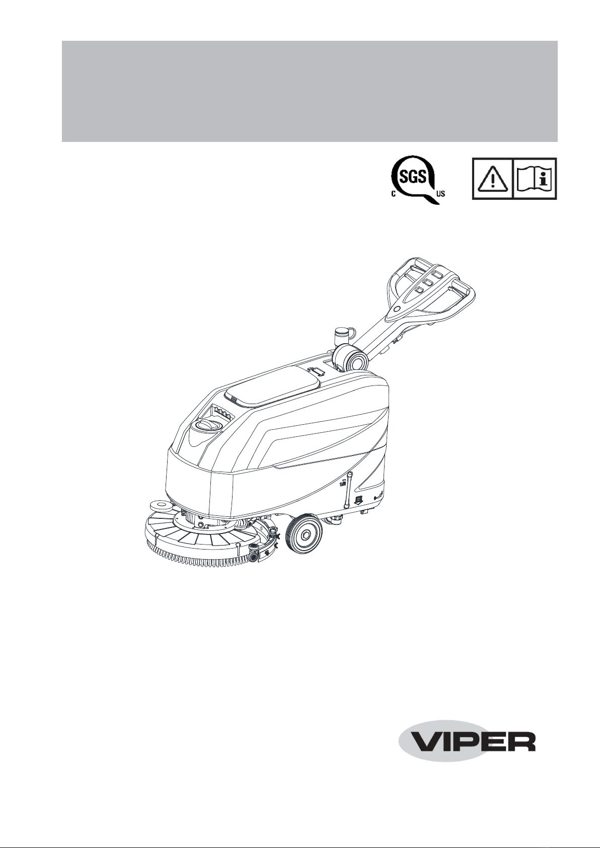
INSTRUCTION FOR USE ENGLISH
4
GENERAL SAFETY INSTRUCTION
Specific warnings and cautions to inform about potential damages to people and machine are shown below.
DANGER!
This machine must be operated by trained and authorized personnel according to guidance of the manual.
Before performing any cleaning, maintenance, repair or replacement procedure, read all the instructions carefully,
ensure to turn the machine OFF and remove the plug from receptacle.
Do not operate the machine near toxic, dangerous, flammable and/or explosive powders, liquids or vapour. This
machine is not suitable for collecting dangerous powders.
Do not wear jewelry when working near electrical components.
Do not work under the lifted machine without supporting it with safety stands.
WARNING!
This machine is intended for COMMERCIAL USE, for example in hotels, schools, hospitals, factories, shops,
offices and rental businesses.
Machines left unattended shall be secured against unintentional movement.
In order to prevent unauthorized use of the machine, the power source shall be switched off or locked, for example
by removing the key of the main switch or the ignition key.
Check the machine carefully before each use. Ensure that all the components have been well assembled before
use. Loose components may cause damage to people and properties.
Never move the machine by pulling the cable. Do not allow the cable to become damaged by a door closing, or
sharp corners. Keep the cable away from heated surfaces.
To reduce the risk of fire, electric shock, or injury, make sure machine is off before leaving.
Use or store the machine indoors in dry conditions, it is not allowed for outdoor use.
The machine storage and working temperature must be between 0 °C and +40 °C, the humidity of air must be
between 30% - 95%.
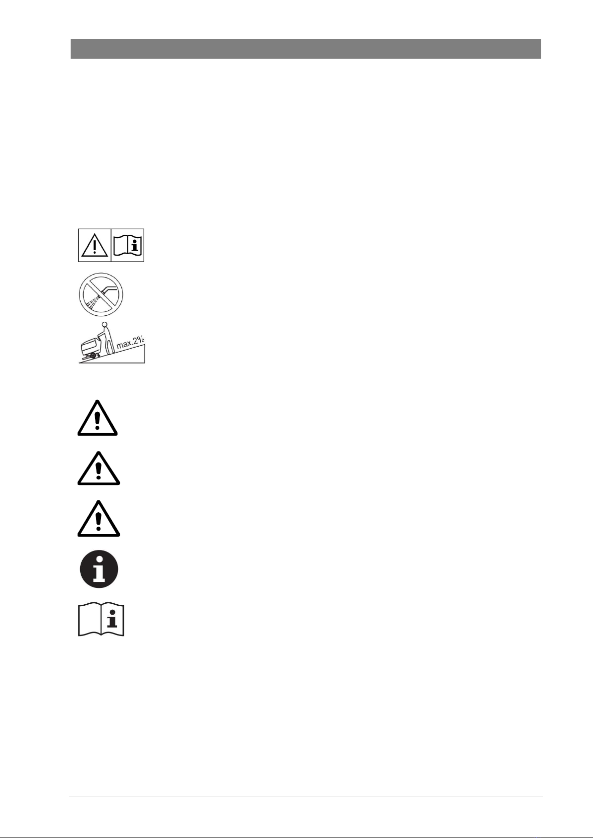
Do not use the machine on slopes with a gradient exceeding the specifications shown.
When using and handling floor cleaning detergents, follow the instructions on the labels of the detergent bottles
and wear suitable gloves and other protective devices.
Use brushes and pads supplied with the machine or defined in the manual. Using other brushes or pads could
reduce safety.
In case of machine malfunctions, ensure that these are not due to lack of maintenance. If necessary, request
assistance from the authorized personnel or from an authorized Service Center.
Take all necessary precautions to prevent hair, jewelry, and loose clothes from being caught by the machine
moving parts.
Do not use the machine in particularly dusty areas.
Do not wash the machine with direct or pressured water jets, or with corrosive substances.
Do not bump into shelves or scaffoldings, especially where there is a risk of falling objects.
Do not lean liquid containers on the machine, use the relevant can holder.
To avoid damaging the floor, do not allow the brush/pad to operate while the machine is stationary.
In case of fire, use a dry powder fire extinguisher. Do not use liquid fire extinguishers.
Do not remove or modify the machine stickers.
Do not tamper with the machine safety guards and follow the scheduled maintenance instructions closely.
Pay attention during machine transportation when temperature is below freezing point. The water in the recovery
tank and in the hoses could freeze and cause serious damage to the machine.
If spare parts need be replaced, order ORIGINAL spare parts from an Authorized Dealers or Retailers.
Return the machine to the Service Center if it doesn’t work as usual or it is in condition such as damaged, placed
outdoors, dropped into water.