30926
TABLE
OF
CONTENTS
SECTION
PAGE
1.
GENERAL
DESCRIPTION
В
о
Control
Panel
。
Center
(Storage)
Compartment
-
Control
Head
Assembly
Door
Switch
上
ユー
スー
で
ーー
ドド
<
ドド
이
이이 우우
Reversible
Door
1
上
1
上
ーー
トー
トー
トド
ドド
ドド
ーー
Shelf
Filter
(Models
5520
&
5530
Only)
..............
Adjustable
Shelves
(Models
5520
&
5525
Only)
Optional
Recorder
....1....%..........1%2...,.....
Temperature
Conversion
Chart
....
oe
Heatad
AirFIOW:
ee
see
ele
e
lale
ŞA
es
ola
e
elele
siye
emele
поме
еее
ее
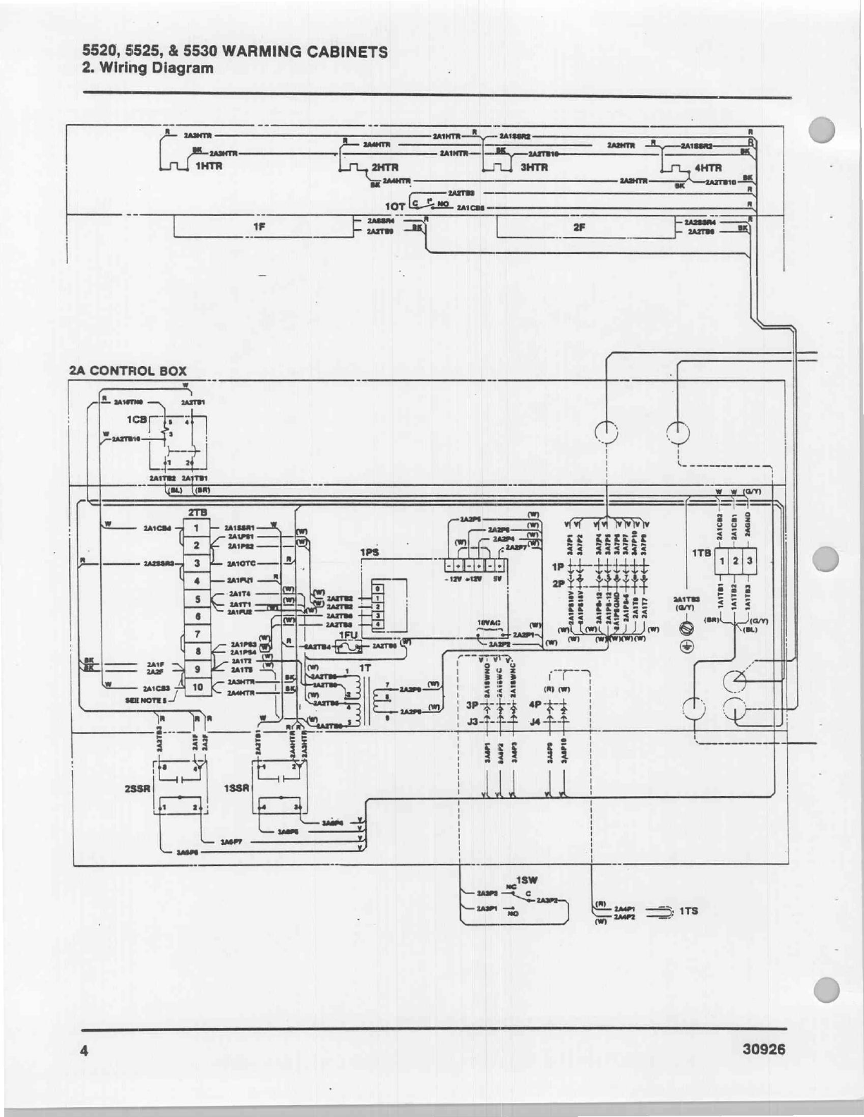
2.
WIRING
DIAGRAM
Warming
Cabinet
Wiring
Diagram
.......................................
4
3.
TROUBLE
ANALYSIS
ПОЛ
МОЕ
О
ео
αρ
ο
ος
оное
в
rea
6
Circuit
Breaker
Trips
7
Unit
Will
Not
Heat
Up
8
Jumper
Connections
on
J3
of
Printed
Circuit
Board
...............
9
UnitiNot'AtProper
Temperature
e
cen
ca
haa
er
aida
aos
eje
10
+5V
Power
Supply
Problem
.....................
11
+11.6V
or
-11.6V
Power
Supply
Problem
12
18
VAC
Power
Supply
Problem
13
24
VAC
Power
Supply
Problem
14
Yellow
Warning
Lit
............
15
We
16
Heater/Fan
Operational
Checks
17
4.
ADJUSTMENTS
&
CALIBRATION
Safety
During
Adjustments
&
Calibration
....................,............
18
Power
Supply
Voltage
Calibration
18
Temperature
Control
Calibration
19
DGOrAGiustMment
“tino
iene
nie
enni
eee
20
Recorder
Calibration
pronao
eae
sure
sie
eds
21
5.
REPAIR
Safety.
DuringRepaif
cdr
e
ian
бое
о
ие
ани
09
23
Access
to
Control
Head
Components
...........
23
Access
to
Control
Box
Components
............
23
Circuit
Breaker
Replacement
23
Fuse
Replacement
............
23
Transformer
Replacement
.....
24
Low
Voltage
Power
Supply
Replacement
........
24
EaniReplacemant:
MMM...
uen
24
Heater
Replacement
..........
24
Thermostat
Replacement
24
Door
Switch
Replacement
26
Recorder
Replacement
(Optional
Equipment)
zes
26
Printed
Circuit
Board
Replacement
...............
se
26
Relay
Meplacemente
...................:0.x».5
302
mee
22
Door
Gasket
Replacement
.......................
ss
22
Reversing'DoonSwWing.
Lu.
ο
siete
nec
eme
Mala
Kase
é
27