Meanwell A301-1K0 User manual

MEANWELL
DC/AC
POWER INVERTERS
A301/A302-1K0 = 1000 Watts
A301/A302-1K7 = 1500 Watts
A301/A302-2K5 = 2500 Watts
A301 = 12VDC in ut
A302 = 24VDC in ut
230VAC out ut
Don
'
t
disassemble
Keep
away from
moisture
Keep away from
fire & heat
Don
'
t stack
inverters
Maintain good
ventilation
2
www. rocontechnology.com.au
Phone: (03) 98306288
WARNINGS:
•
For indoor use only.
•
Do not use if the inverter is damaged.
•
Hazardous voltage inside - do not attem t to o en or re air.
•
Read all manuals and instructions before connecting or using the inverter.
•
Only connect 220/230/240V AC a liances that are in good condition.
•
For inde endent use, do not connect to the AC electricity grid.
•
Batteries require regular maintenance. Once aged, batteries should be changed by
qualified ersonal as failed batteries may cause fire or other hazards.
FEATURES:
•
12 DC or 24 DC input voltage available.
•
Peak Power Technology runs appliances with high startup current.
•
Built in safety protection against AC power overload, low and high battery voltages.
•
Heavy Duty power leads included for direct battery connection (except 2500W).
•
Approved AS/NZS power outlet sockets.
•
Twin power outlet sockets.
•
Temperature controlled automatic cooling fan.
•
ON/OFF remote control (optional).
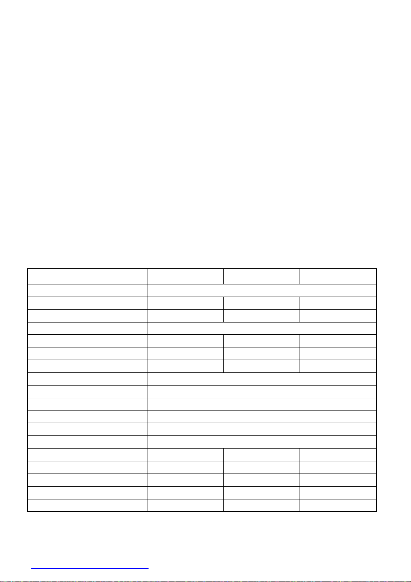
SPECIFICATIONS:
Part No. A301/A302-1K0 A301/A302-1K7 A301/A302-2K5
Input oltage 12 /24 Battery or DC source (-15% ~ +25%)
Input Current: (Max DC Amps) 110A/55A 170A/85A 250A/130A
Input Standby Current 0.4A/0.2A 0.6A/0.36A 0.9A/0.6A
Output 230 olts AC, 50Hz (Modified Sine Wave)
Continuous Output Power
(Watt)
1000W 1500W 2500W
Peak Output Power < 5-30 min
1200W (30 min) 1700W (30 min) 2700W (5 min)
Surge Output Power 2400W 3000W 5000W
Efficiency (typical) 82%/85%
Low Battery Alarm 10±0.5 /21.0±0.8
Low Battery Shutdown 9.5±0.5 /20.0±0.8
High Battery Shutdown 15.5±0.5 /30±1
Cooling Automatic temperature controlled > 40°C (NTC) fan on
Thermal Shutdown 60±5°C
Fuse Quantity & Size 5x30A/20A 10x30A/20A 12x30A/15A
Fuse Location Internal* Internal* Internal*
Connection Cables x2 1000mm long 1000mm long
Dimensions (L x W x H) 310x210x85mm 455x210x85mm 430x210x159mm
Weight 3.3kg 5.5kg 8.7kg
* Internal fuses should only be replaced by qualified personal.
3
www. rocontechnology.com.au
Phone: (03) 98306288
WHAT IS AN INVERTER?
Inverters are designed for powering household appliances from a battery or low voltage
DC source. They are electronic devices that convert battery power to AC mains power.
Inverters are compact and often lightweight making them an ideal source of portable
mains power. Thanks to their portability they are commonly used in cars, caravans,
motor homes, boats, 4WD's, utility vehicles, trucks and buses.
Using an inverter with standard household appliances is a much cheaper option than
purchasing specialized 12 or 24 appliances for times when mains power is not
available.
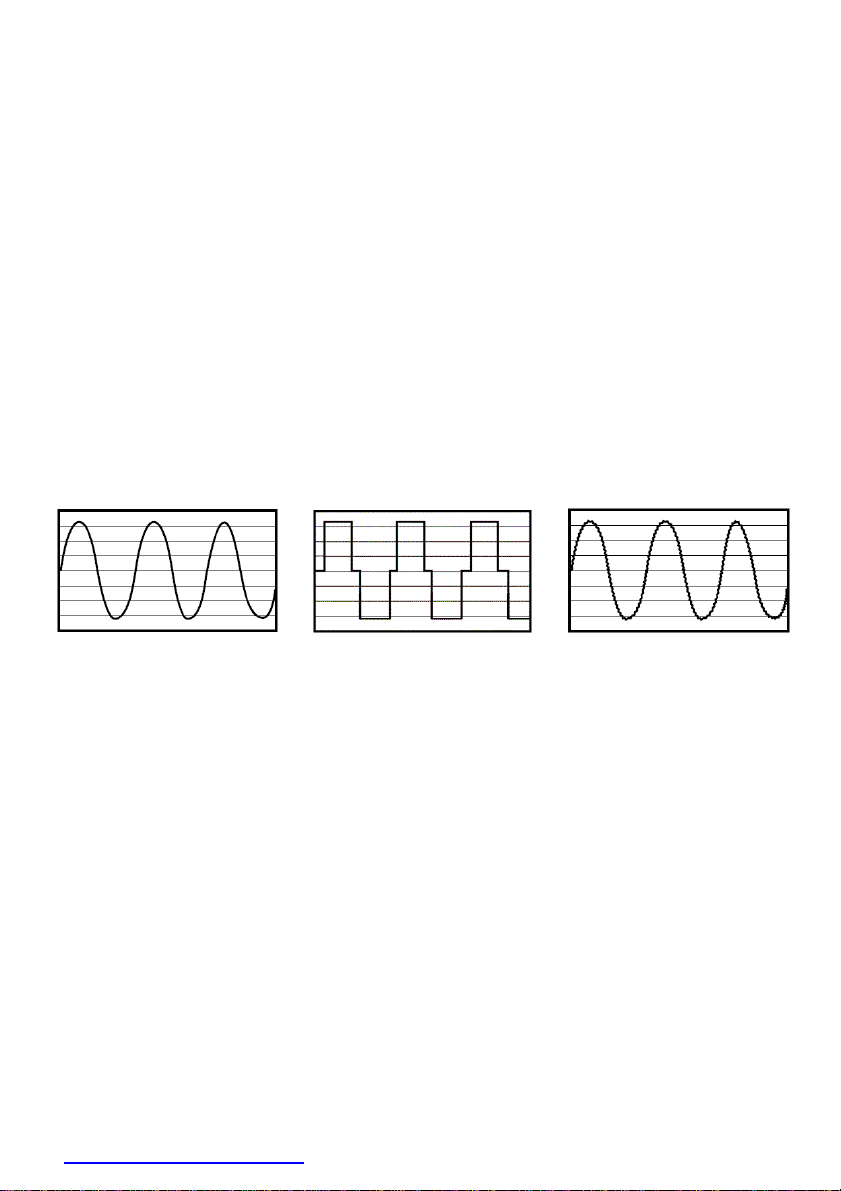
There are two different types of inverters, Modified Sine Wave (MSW) and True Sine
Wave (TSW). The difference between the two is how close the output replicates normal
mains power.
These graphs show the difference in output between mains power, MSW and TSW
inverters.
400
400
400
300
300
300
200
200
200
100
100
100
0
0
0
-100
-100
-100
-200
-200
-200
-300
-300
-300
-400
-400
-400
MAINS POWER (SINE
WAVE)
MODIFIED SINE
WAVE
TRUE SINE
WAVE
Logically it follows that the process used in a TSW inverter is more complex than a MSW
inverter and subsequently they are a lot more expensive.
In reality most electric appliances operate unaffected on a modified sine wave and hence
they are more common in applications requiring intermittent use.
True sine wave inverters are reserved for use on sensitive electrical appliances (such as
medical equipment) and in permanent or continuously operating installations.
Inverters are available with different power output levels to suit the type of appliances to
be powered. Small inverters are designed for powering one small low power electrical or
electronic appliance. Larger inverters can be used to power multiple small appliances or
one larger appliance. Typically inverters are not suitable for running appliances with very
high power requirements such as electric heaters, stoves and air conditioners. This is due
to their high current draw and the resultant battery consumption.
4
www. rocontechnology.com.au
Phone: (03) 98306288
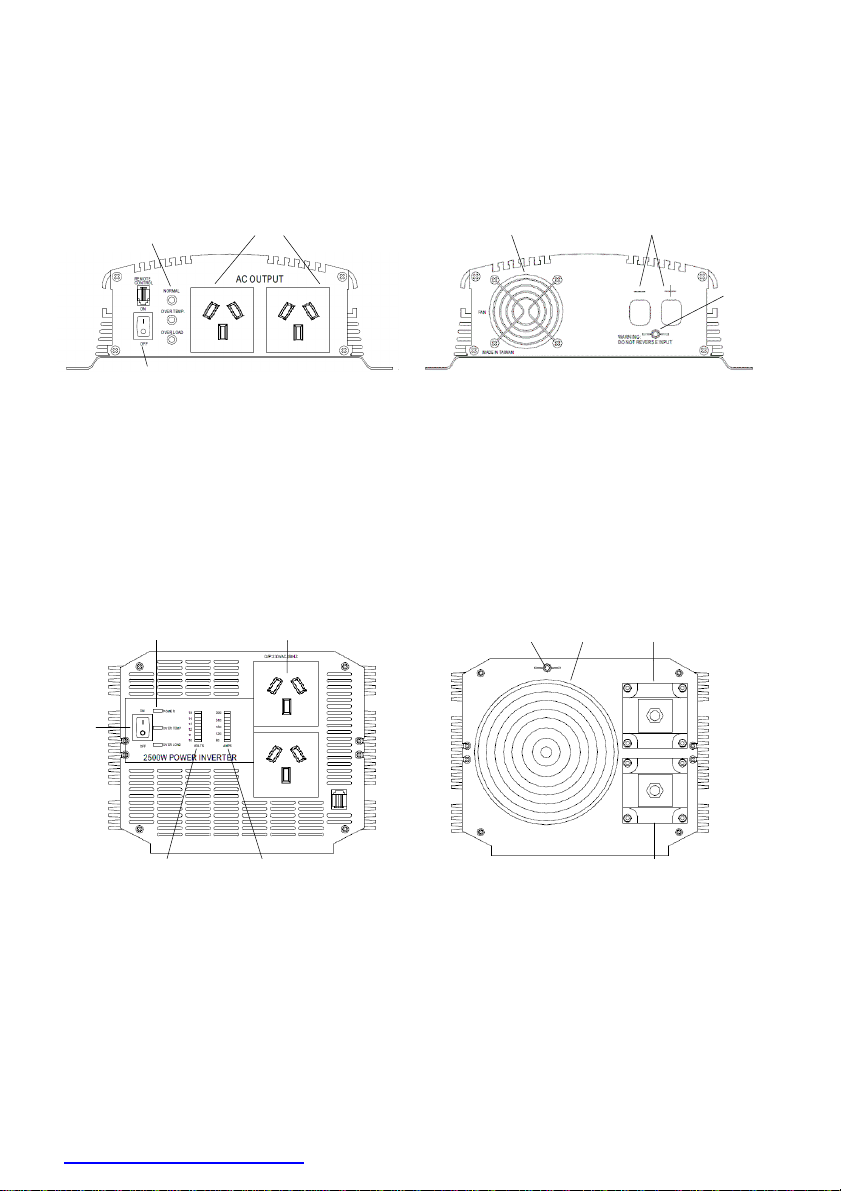
CONNECTIONS / CONTROLS & ACCESSORIES
After unpacking your inverter take a moment to check that you have the correct model
(A301 = 12 , A302 = 24 ) and all the correct accessories are included. Familiarize
yourself with the connections and the controls on the inverter.
Part No. A301/A302-1K0 & A301/A302-1K7
POWER & FAULT
LIGHTS
AC OUTPUT SOCKETS
FAN
DC CABLE ENTRY
POWER ON
SWITCH
FRONT
REAR
Supplied:
•
Operating instructions
•
Negative (Black) DC connection lead fitted with ring terminal
•
Positive (Red) DC connection lead fitted with ring terminal
Part No. A301/A302-2K5
FRONT
REAR
Supplied:
•
Operating instructions
POWER ON
SWITCH
AC
OUTPUT SOCKETS
POWER & FAULT
LIGHTS
OLTS INDICATOR
AMPS INDICATOR
-
DC TERMINAL (BLACK)
FAN
+ DC TERMINAL (RED)
CHASSIS
GROUND
CHASSIS
GROUND

5
www. rocontechnology.com.au
Phone: (03) 98306288
PLACEMENT / LOCATION / MOUNTING OF INVERTER
Caution:
•
The inverter must be mounted away from any flammable items and gas appliances.
•
Batteries should be mounted in a separate well-vented area/enclosure.
•
The inverter must always be protected from rain, water and moisture.
Meanwell inverters are designed for indoor use only. For best performance the inverter
must be used or mounted in a cool, dry, clean and well-ventilated area. For best T and
Radio reception keep the inverter as far away from T 's, radios, antenna cables and
antennas as possible.
All models are supplied with mounting flanges for use in permanent installations in
4WDs, caravans, motor homes and boats. The inverter should be mounted on a suitable
horizontal (recommended) or vertical panel, with at least 15cm clearance from the front
and rear panels of the inverter to provide good ventilation for the cooling fan.
SUITABLE POWER SOURCE:
In order to operate the inverter a suitable 12 or 24 DC power supply is required. This
can be vehicle or caravan batteries, a portable power pack or battery bank joined in
series and/or parallel to produce 12 or 24 DC. For most applications, deep cycle
batteries are recommended for best performance.
The size of the batteries used will determine how long the inverter will supply power to
an appliance and how well the inverter will perform. Most batteries are marked with
their size in Amp hours (Ah).
Because the inverter is capable of drawing high currents the inverter should only be
connected to suitable size batteries. Connection to undersized batteries could damage
the batteries and may result in the inverter shutting down within a short period due to
low battery voltage.
The amount of power drawn from the batteries is proportional to the inverter load.
Part No. A301/A302-1K0 A301/A302-1K7 A301/A302-2K5
Recommended minimum
Battery Size 80/40Ah 120/60Ah 240/120Ah
Run time with max. load
and min. battery size
20min 20min 20min
Run time for a 100W globe
and min. battery size 6 hours 8 hours 16 hours
Ideal battery size 120/60Ah to
400/200Ah
120/60Ah to
400/200Ah
400/200Ah or
higher

6
www. rocontechnology.com.au
Phone: (03) 98306288
CONNECTION TO POWER SOURCE & EARTHING
Caution:
•
ven though the inverter is powered from batteries, it still produces Dangerous
High Voltage AC power and has the potential to fatally injure if incorrectly
installed or used.
•
Before making any connections ensure the inverter is switched off and no AC
appliances are plugged into the AC output sockets.
•
Double check battery negative and positive posts before making the input
connections, a wrong connection (Reverse polarity) will cause the fuses to blow
and may damage the inverter.
•
A small spark (electrical arc) can occur when making the final battery connection;
this is most common when the inverter has not been used for a long time. This spark
is caused by the inverter's large input capacitors charging quickly. To minimize this,
make the last connection quickly and completely.
•
Do not make any connections if there are any flammable fumes present or any
volatile fuels or gases are near.
•
Batteries can be dangerous, follow all battery manufacturer's instructions and
warnings.
•
Meanwell inverters are designed FOR IND P ND NT US ONLY. The inverter cannot
be connected to household wiring whether the building is connected to the
electricity grid or not.
The 1000W and 1500W inverters can be connected to a power source on a
temporary basis with the supplied DC leads (see the section on Temporary
Connection) or all units can be hard wired for a permanent installation with suitably
sized cables and hardware for your application (see the section Hard Wired
Connection). Regardless of which connection method is used it may be
advantageous to earth the inverter case or chassis, see the section on External
Earthing for more details.
TEMPORARY CONNECTION:
•
Connect the ring terminal on the black lead to the negative DC supply or (-) battery
terminal. Do not use alligator cli leads to extend the connections!
•
Connect the ring terminal on the red lead to the positive DC supply or (+) battery
terminal.
"HARD WIRED" CONNECTION:
When mounting the inverter in a vehicle, caravan, boat, truck or home it may be
preferable to use longer DC battery cables than those supplied, so that the inverter
can be placed in a more convenient, cooler or more protected location.
If longer cables are required only use suitably insulated automotive battery cable
according to the following table:
7
www. rocontechnology.com.au
Phone: (03) 98306288
P/No. A301/A302-1K0 A301/A302-1K7 A301/A302-2K5
Up to 1.5m
2/6AWG(33/14mm²) 00/2AWG(67/33mm²) 000/0AWG(85/50mm²)
3m 0/4AWG(50/21mm²) -/0AWG(100/50mm²) Not recommended
6m 00/2AWG(67/33mm²) Not recommended Not recommended
•
It is recommended that a circuit breaker or high current fuse be placed in the DC
positive (+) line close to the batteries.
Part No. A301/A302-1K0 A301/A302-1K7 A301/A302-2K5
Fuse or Circuit
Breaker size (+)
Only
125/75AMP 250/125AMP 300/150AMP
•
It is recommended that a heavy duty battery switch with a current rating higher
than the fuse be fitted in the DC positive (+) line close to the batteries to allow the
supply to the inverter to be switched off, this can also be achieved by using a circuit
breaker which has a trip facility.
•
Positive and Negative cables should be run close together to reduce cable
inductance. The cables should also be protected from any damage.
•
Any connections should be made securely using the proper hardware. Procon
Technology recommends the use of DeOxit as a contact cleaner to improve
conductivity and protect metal. See… www.procontechnology.com.au/deoxit.htm
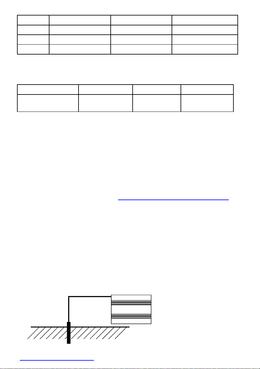
EXTERNAL EARTHING: (OPTIONAL)
Meanwell inverters have been internally bonded for safety, by connecting the AC socket/s
earth pin to the inverter case. If the inverter is used in a stationary land based application
or if the inverter is causing interference with T sets or radios it is recommended that an
external earth connection is made by one of the following methods:
•
External Earthing Stationary Applications - Connect an earth wire (preferably solid
green or green with yellow stripe) from the external earth connection (Chassis GND) on
the rear of the inverter to a metal stake or pipe that is driven into the ground at least
1.2m (or according to local electrical safety authority recommendations).

8
www. rocontechnology.com.au
Phone: (03) 98306288
•
External Earthing Mobile Applications - Connect an earth wire (preferably solid green
or green with yellow stripe) from the external earth connection (Chassis GND) on the
rear of the inverter to the chassis of the vehicle or ground wires on a boat.
CHASSIS CONNECTION
OPERATION
Caution:
•
Never connect the AC output of the inverter to normal fixed building wiring or any
wiring connected to the mains grid. Normally AC wiring contains a M N link - this
neutral to earth link can damage the inverter and compromise safety.
•
This inverter is designed for direct connection to appliances however extension
leads and power boards can be used for low wattage appliances.
PROTECTION FEATURES
Meanwell inverters include sophisticated circuitry that monitors the operation of the
inverter and turns the inverter off if a problem is detected. A fault light will illuminate
and an audible alarm may be heard if this occurs. This prevents damage to the inverter,
batteries and/or appliance being powered.
•
Low Battery - This feature will sound an alarm when the battery system powering the
inverter is low. It is recommended that the appliance is turned off, then the inverter is
turned off and the batteries recharged before switching on again.
If the appliance is allowed to continue to run, the inverter will turn off when the
batteries are very low to prevent over discharging the batteries or damaging the
inverter. This will cause a sudden disruption of power to the appliance that may cause
problems for some devices. e.g. computers that need to be shut down properly.
•
High Battery - This feature will shut down the inverter when the battery system is too
high in voltage. This prevents damage to the inverter. An over voltage condition could
occur if the wrong battery system is used or a fault occurs whilst attempting to charge
the battery when it is connected to the inverter.
•
Overload - This feature will turn the inverter off when the total load connected to the
inverter exceeds the inverter's rating (see
"
Determining suitable loads/appliances
"
).

9
www. rocontechnology.com.au
Phone: (03) 98306288
This may occur due to highly inductive loads such as any appliance with a motor
causing a sudden peak load on the inverter.
If this occurs, switch "OFF" the appliance and the inverter. After 5 seconds turn the
inverter "ON" and the inverter will provide power again. Turn the appliance "ON", if the
inverter shuts down more than 3 times, it is likely that the appliance is drawing more load
than the inverter can supply, and a larger inverter would be recommended. Note if the
load is a motor ensure that it is started under no-load conditions or try fitting a soft-
start device to the motor (or purchase an appliance with one already fitted).
•
High temperature - If the inverter has reached a high temperature, this feature will
sound an alarm and then turn the inverter off. This may occur from continuously
running high loads for long periods, due to high ambient temperatures or due to poor
ventilation. If this occurs, turn the inverter off and allow it to cool before resuming
operation. If possible reduce the load on the inverter and improve ventilation.
DETERMINING SUITABLE LOADS/APPLIANCES:
The inverter is fitted with 2 approved AS/NZS Australian socket outlets. Both sockets can
be used, as long as the combined load (Watts required to run appliance) does not exceed
the inverter's continuous rating and the load connected to one socket does not exceed
2400 Watts (10Amps). All appliances have a rating plate that shows the amount of power
(Watts) used or the current (Amps) drawn under normal conditions.
The following table shows the maximum combined AC Watts or AC Amps which can
be run by the inverter for less than 30 minutes continuous.
Part No. A301/A302-1K0 A301/A302-1K7 A301/A302-2K5
AC Combined max load (Watts)
1200W 1700W 2700W
AC Combined max load (Amps)
5A 7A 11A
Some appliances that use an electric motor or transformer may draw 2 to 6 times their
rating when first turned on. These are called inductive loads and are the most difficult for
the inverter to run. For these appliances it is often a matter of trial and error to see what
size inverter will run them, if in doubt always use a larger inverter using the above table
as a guide.

10
www. rocontechnology.com.au
Phone: (03) 98306288
CONNECTING AN APPLIANCE AND RUNNING THE INVERTER
•
Connect the appliance AC plug to the inverter AC outlet socket.
•
Switch the inverter
"
ON
"
, the
"
Green
"
power light will illuminate to indicate operation.
•
Turn the appliance
"
ON
"
, if the appliance is fitted with an
"
On/Off
"
switch always
switch the inverter on before switching the appliance on and always turn the
appliance off before switching the inverter off. If necessary, use a power board
with switches.
•
When not in use, turn the inverter off. Leaving the inverter on, even with no AC
load connected, will drain the battery.
TROUBLESHOOTING / FAQ:
Q. Why does the inverter turn itself off?
A. If the red "O ER LOAD" light illuminates this indicates that there is a problem, and
the inverter will usually turn off. Most commonly this would be caused by an
appliance that is drawing too much power and for too high or too low battery voltage.
Note a low input voltage can occur when a voltage drop, due to insufficient sized
cables or batteries. Or when there are poor connections to the input to the inverter.
Initially an audible warning will occur and only after a further drop in battery voltage
does the unit shut down. Operation is restored once the battery voltage returns to
normal. All other "O ER LOAD" faults will cause the inverter to shut down until it is
switched off and on again.
Q. The inverter will not run my a liance even though the a liance label indicates that
it draws less ower than the size of the inverter?
A. Electrical appliances can be divided into three groups by the way they draw energy
(current) from their power supply. These groups are "Resistive", "Inductive" and
"Capacitive" appliances or "loads". Some appliances are a combination of these loads.
•
The most common resistive loads are incandescent or filament lights and heating
elements. These devices are non-linear and draw a higher current at start up and,
after a short delay once they “warm up”, they always draw a constant power or
current from the inverter, that is a 100 Watt light will draw approximately 100 Watts
from the power supply at all times. Resistive loads are the easiest load for an inverter
to run provided that it can handle the start-up current. Note a light dimmer with
"
soft
start
"
capability can be used to reduce the start-up current.
•
Inductive loads such as an electric motor require a large rush of power (surge current)
to start and then usually draw a more constant power once running. Inductive loads
contain coils of wire (motors, transformers, ballasts, solenoids) When the power is
first turned on these coils of wire draw a large inrush or surge current which forms the
magnetic flux (magnetic field) which allows these devices to work.
•
The most common inductive appliances are: refrigerators, air conditioners, pumps,
transformers, power tools and fluorescent lights. These appliances can draw 2 - 6
times their normal running power at start up. e.g. to run a 190 Watt refrigerator a 600

11
www. rocontechnology.com.au
Phone: (03) 98306288
or 1000 Watt inverter may be needed.
•
Capacitive loads such as many T 's or many electronic appliances (desktop computer,
monitor etc.) require a large surge current to start only when they have not been used
for a while. This is often due to large capacitors in the switched mode power supply
that must be quickly charged when the appliance is turned on. If the appliance has not
used for a while these capacitors slowly go flat. If the inverter trips on overload then
restarting a few times may allow these appliances to work.
•
There are some appliances such as large refrigerators, air conditioners and other
compressor driven appliances that have extremely high startup currents, because
they have an electric motor that must start under load. These appliances are not
recommended for use with an inverter. However check with the manufacturer as
motors with "soft-start" capability may be capable of being used with an inverter.
Q. The inverter is owering my ortable television, but I cannot get a clear icture?
A. In poor reception areas it is quite common to have some interference on a portable T
(such as faint lines on the screen) when operating on all modified sine wave inverters.
•
To improve your picture quality:
-
Keep the inverter as far away from the T as possible.
-
Use an external long range or fringe area T antenna with good quality coax cable.
-
Earth (using Chassis GND) the inverter (see the section on Earthing)
Q. Can I run fluorescent lighting from my inverter?
A. Most portable fluorescent work lamps should operate fine on an inverter even
though they may be slow to start.
•
Fluorescent lights are an inductive and capacitive load and often draw at least
twice as much power from the inverter than their normal rating during start up.
•
Normal household fluorescent lights should be avoided, because they contain power
factor correction capacitors. Power factor correction is used in buildings installations
to help smooth out the inductive effects of fluorescent light ballasts. If used with
portable power inverters the power factor correction is effected by the harmonic
distortion in the modified waveform, this causes a high load on the inverter that can
overload the unit. If normal household fluorescent lights must be used, you will need
to have a qualified electrician remove the power factor correction capacitor. The light
should then be marked
"
For Inverter Use only
"
. Or simply use a fluorescent light with
an electronic ballast!
Q. Why does it damage the inverter if the battery leads are connected in reverse?
A. Your inverter uses sophisticated electronics to convert DC battery power to AC
mains power. If you accidentally connect the inverter to the batteries incorrectly
(reverse polarity) a large current will be drawn by the inverter which will blow the
protection fuses, as this occurs some of the high current could damage sensitive
electronic components. Because of this risk it is important to always double-check
the batteries polarity before making the input connections.

12
www. rocontechnology.com.au
Phone: (03) 98306288
Q. How do I check or change the fuses?
A. The inverter contains internal fuses; these should only be checked or replaced by
a suitably qualified person.
THE DC SUPPLY MUST BE DISCONNECTED BEFORE ANY REPAIR, THEN TURN THE
ON/OFF SWITCH OF THE IN ERTER "ON" TO DISCHARGE THE CAPACITORS.
Q. Why does the fan only o erate sometimes?
A. These inverters feature a temperature controlled automatic cooling fan, that only
operates when needed. This allows the inverter to run very quiet when under low load
conditions.
Q. Why do some ower tools not work ro erly?
A. Some power tools use PWM variable speed controllers to vary the tool's speed as the
trigger is squeezed. These power tools switch the power on and off very quickly in a
similar way to how the inverter works. Because of this, some may not function
properly with the inverters MSW output. On the other hand, a speed control can
reduce the start-up current of the motor and allow an appliance to be used with an
inverter where otherwise it would cause it to overload.
Q. Can I run a la to com uter?
A. Most laptop/notebook computer AC power adapters work perfectly fine with the
inverter's modified sine wave output. Some however are more sensitive and may
not function properly. If your power adaptor does not function or causes a humming
noise or interference on the screen it is probably not suitable. Try using a universal
AC adapter with your laptop or try using a TSW inverter.
Q. Can I connect lights with dimmers to the inverter?
A. Some old "TRIAC" type AC light dimmers may not work with a MSW inverter - try a
TSW inverter instead. Most new "MOSFET" type AC light dimmers and motor speed
controllers will work with MSW inverters but check with the manufacturer first. The
Clipsal 32 and Kambrook KD2 power board with dimming outlet were tested with a
Meanwell MSW inverter and they worked fine, hence some AC dimmers can work
with MSW inverters! Note, dimmers and speed controllers with "soft-start" capability
are an excellent way to reduce and limit the start-up current impact on the inverter.

13
www. rocontechnology.com.au
Phone: (03) 98306288
WARRANTY
Meanwell Modified Sine Wave Inverters are covered by a 12 Month Warranty. Failure
to follow the operating instructions may damage the inverter and may void the
warranty. Please read the operating instructions carefully before use.
DISCLAIMER
All specifications are subject to change without notice. Any circuit diagrams or assembly
diagrams provided with equipment are for reference purposes only. Procon Technology
makes no representation or warranty of any kind to the customer that they are
qualified to make any repairs to our products, or that they are qualified to replace any
parts. The customer assumes all responsibility for repairs or modifications not carried
out by a qualified technician approved by Procon Technology.
This manual suits for next models
5
Table of contents
Other Meanwell Inverter manuals

Meanwell
Meanwell NTS Series User manual

Meanwell
Meanwell TS-700 User manual

Meanwell
Meanwell TS-1500 User manual

Meanwell
Meanwell TS-200 User manual

Meanwell
Meanwell ISI-501 Series User manual

Meanwell
Meanwell ISI-501 Series User manual

Meanwell
Meanwell TN-3000 User manual

Meanwell
Meanwell PB-300 User manual

Meanwell
Meanwell NTS-450 Series User manual

Meanwell
Meanwell ERG-5000 User manual


