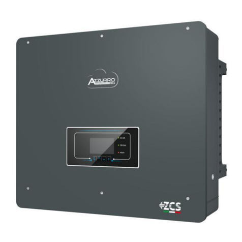
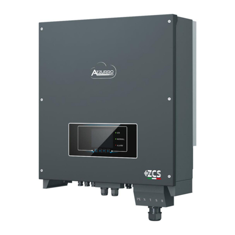
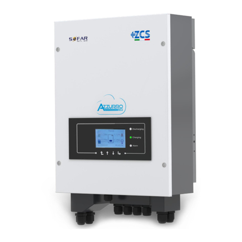
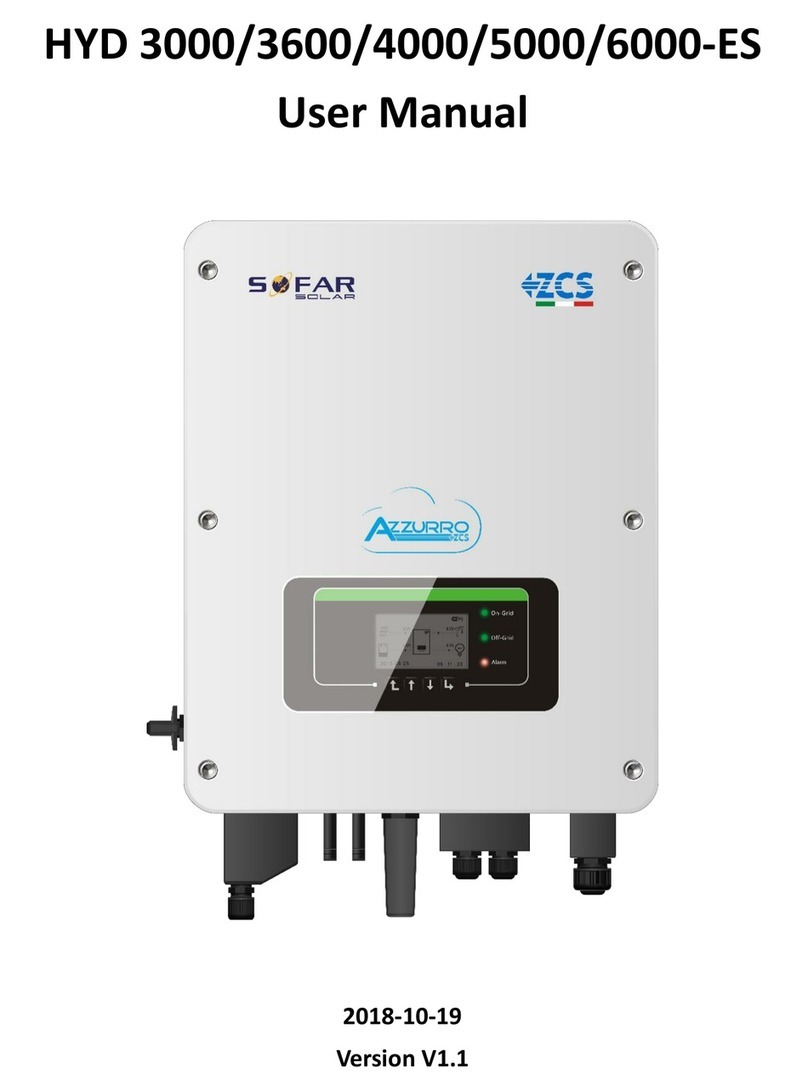
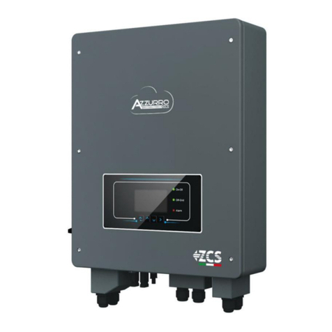
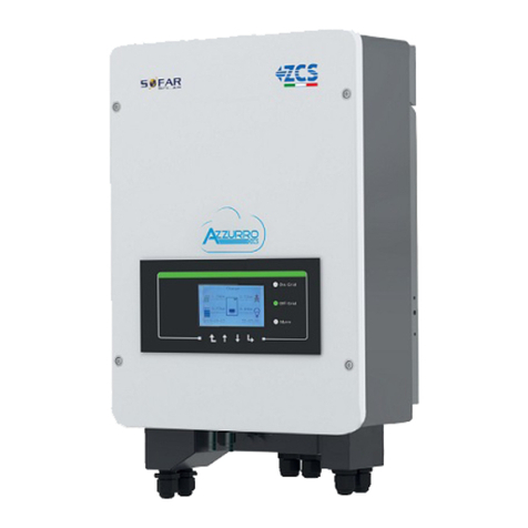
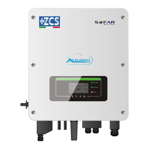
ZCS Azzurro HYD3000-ZP1 User manual

QUICK GUIDE
HYD3000-HYD6000-ZP1 HYBRID
INVERTER
Rev. 1.0 –23/10/2023
Always wear protective
clothing and/or personal
protective equipment
General notice -
Important Safety
Instructions
1
Always consult the
manual

TABLE OF CONTENTS
TABLE OF CONTENTS
1. INSTALLATION AND DISTANCES
2. INSTALLATION
3. DISPLAY & BUTTONS
4. MAIN MENU
5. CONNECTING TO THE GRID
6. PHOTOVOLTAIC CONNECTIONS
7. COMMUNICATION CONNECTION –COM PORT
8. BATTERY CONNECTION
9.1 SETTING PHOTOVOLTAIC CHANNELS
9.2 SETTING BATTERY CHANNEL
10.1 MEASURING EXCHANGE VIA CT SENSOR
10.2 MEASURING EXCHANGE VIA DDSU METER
10.2.1 DDSU METER SETTING ON EXCHANGE AND INVERTER
10.2.2 MEASURING EXTERNAL PRODUCTION VIA DDSU METER
10.2.3 DDSU METER SETTING ON EXTERNAL PRODUCTION
10.2.4 CONFIGURING DDSU EXCHANGE METER AND DDSU PRODUCTION METER
10.2.5 CHECKING CORRECT DDSU METER READING
10.3 READING VIA DDSU METER
10.3.1 SETTING DTSU METER
10.3.2 CHECKING CORRECT DTSU METER READING
11. INITIAL SET UP PROCEDURE
12. INITIAL SET-UP
13. CHECKING THE CORRECT OPERATION
14. CHECKING THE INVERTER SETTINGS
15. ZERO FEED-IN MODE
16. LOGIC INTERFACE (DRMS0)
17.1 EPS MODE (OFF GRID)
17.2 EPS MODE (OFF GRID) - WIRING PROCEDURE AND INSTALLATION TYPES
17.3 EPS MODE (OFF GRID) –OPERATION
17.4 EPS MODE (OFF GRID) - MENU ENABLING
18.1 OFF GRID MODE ONLY
18.2 OFF GRID MODE ONLY - START UP
19.1 PARALLEL INVERTER MODE - CONFIGURATION
19.2 PARALLEL INVERTER MODE - SETTINGS
20. FIRMWARE UPDATE
21. SELF-TEST
22. % CHARGE MODE
23. QUICK INFO ON SYSTEM STATUS
24. OPERATING STATUSES IN AUTOMATIC MODE
2

1. INSTALLATION
1. INSTALLATION AND DISTANCES
Dimensions and distances to be
observed:
To guarantee adequate room for both installation and effective heat dissipation, make sure there is ample space
around the 1PH HYD3000-HYD6000-ZP1 residential energy storage inverter.
3

1. INSTALLATION
2. INSTALLATION
Installing the base:
If holes cannot be drilled on the ground,the battery
expansion modules must be secured on the wall
Levelling instrument
Wall
Ground
Baseboard
60mm
10~25mm
Left Right
A
Enlarged drawing A
M6
5 N·m
First Battery
PACK
Second Battery
PACK
Third Battery
PACK
Inverter
①
②
③
Step 1: Place the base against a wall,
leaving a gap of 10-25 mm between the
base and the wall. Adjust the position of
the holes using a level and mark them
with a felt-tip pen.
Step 2: To install the base, remove it, and
drill the holes using an impact drill with
an 8mm diameter bit, drilling to a depth
of 60-65 mm. Tighten the expansion
screws to firmly secure the base in place.
Step 3: Use a felt-tip pen to mark the
holes for attaching the battery modules
and inverters, following the dimensions
shown in the figure below.
Installing the modules:
Step 1: Align the first battery
module to the base.
Step 2: Install the connectors on
both sides and tighten the six
screws using a cross screwdriver.
Step 3: Install the remaining
battery modules and inverter from
bottom to top. (Before installing the
next module, ensure that the
screws on the side connectors of
the previous module are firmly
tightened).
4

1. INSTALLATION
Installing the support panel:
Step 1: Use an impact drill (φ 8mm,
depth 60-65 mm) to drill the holes.
Reposition and drill the holes in case of
significant deviation.
Step 2: Install support panel B on the
wall and fasten the expansion bolt.
Step 3: Adjust support panel A, making
sure that the holes on both panel A and B
are perfectly aligned.
Step 4: Connect and secure panel A and B
using M6*16 screws.
Installing the cover:
After ensuring the correctness and reliability of the electrical connections, install the outer protective cover
and secure it with the screws.
5

1. INSTALLATION
3. DISPLAY & BUTTONS
1
2
3
4
1 System power indicator 3 Button
2 System status indicator 4 LCD screen
MENU/BACK
UP
DOWN
ENTER/FORWARD
System status Indicator
Blue LED Green LED Red LED
On-Grid On
Standby (On-Grid) Intermittent
Off-Grid On
Alarm Intermittent
Icon Battery capacity
80-100%
60-80%
40-60%
20-40%
0-20%
6

4. MAIN MENU
Main menu
1. Basic settings
2. Advanced settings
3. Statistics
4. System Info
5. Event list
5. Software Update
7. Real-time battery info
From the main menu, press
“Menu/Back” to enter the main
menu.
1
. Language
2
. Date and Time
3
. Safety parameters
4.
Working mode
5. Self
-test
6
. Config. input Channels
7
. EPS Mode
8
. Commun. Address
.
Select
.
1
. Battery parameters
2
. Active battery
3
.Feed-in limit
4
.IV Curve Scan
5
. Logic interface
6
. Factory reset
7
. Parallel settings
8
. Bluetooth Reset
9
.CT Calibration
10
.Set electricity meter
11
. Neutral Point Grounding
PWD: 0715
1
. List of current events
2
. List of historical events
Start Update ...
PWD: 0715
Today
Week
Month
Year
Life
Cycle
PV prod. PV prod. PV prod. PV prod. PV prod.
AutoCon AutoCon AutoCon AutoCon AutoCon
Export Export Export Export Export
Consumption Consumption Consumption Consumption Consumption
AutoCon AutoCon AutoCon AutoCon AutoCon
Import Import Import Import Import
1
. Inverter Info
2
. Battery Info
3
. Safety parameters
4
. Debug info
5
. PCU info
6
. BMS info
Statistics:
7

5. CONNECTING TO THE GRID
Step 0: Select the
suitable cable type
and specifications.
Step 1: Thread the
wire through the
terminal.
Step 2: Align the wire
with the marking, insert
it into the hole on the
terminal and tighten it.
Step 3: Push the
terminal forward
until a "click" is
heard.
Step 4: Connect the attached load
terminal to the inverter's load port and
push the terminal forward until it clicks
into place.
Item Description Recommended
cable type
Recommended cable
specification
AC Grid
L (U)
Multi-core copper
cable for outdoor
use
Cross-section area of the
conductor: 8 AWG
N (W)
PE (O)
LOAD
L (U)
Multi-core copper
cable for outdoor
use
Cross-section area of the
conductor: 8 AWG
N (W)
PE (O)
6. PHOTOVOLTAIC CONNECTIONS
Cross-sectional area (mm2)
Outer cable area (mm2)
Range Recommended
value
4.0~6.0 4.0 4.5~7.8
Recommended specifications for
DC input cables
Insert the crimped positive and negative cables into the corresponding photovoltaic connectors.
1. Positive contact
2. Negative contact
Make sure that the DC parameters of the strings are acceptable according to the technical specifications given in the datasheet and in the
Azzurro ZCS configurator. In addition, check that the polarities of the photovoltaic cables are correct.
Before removing the positive and negative PV connectors, make
sure that the DC rotary circuit breaker is in the OFF position.
3. Positive connector
4. Negative connector
Prepare the positive and negative photovoltaic cables.
Use a MC4 wrench to disconnect the
photovoltaic connectors
8

NOTE: Both MPPT inputs of the inverter must be populated, even if the system has only one string. Use a
“Y” cable or a square to split the string.
Configure the inverter in parallel mode:
Basic settings
→
Channel configuration
→
Input Channel 3: PV1 Input;
Input Channel 4: PV1 Input
ATTENTION Before connecting/disconnecting the strings to the inverter, check
that the DC circuit breaker on the side of the inverter is in the OFF position.
7. COMMUNICATION CONNECTION –COM PORT
Icon Definition Function Note
1Link Port 1 Parallel Signal Output
Parallel Signal Port (RJ 45)
2Link Port 0 Parallel Signal Input
3Dip switch Link Port 1 Enables and disables the
resistor
The selector can be set to 0
(selector UP) or 1 (selector
DOWN) A setting of 1 enables
the resistor, while a setting of 0
disables it
4Dip switch Link Port 0
Connections for master/slave mode:
9

Port connection of COM communication:
PIN Definition Function Remark
1N/D N/D
2UC-A RS485 -A differential signal Inverter monitoring signal 485
3UC-B RS485 -B differential signal
4EN+ RS485 + differential signal Battery signal 485
5EN- RS485- differential signal
6MET-A RS485 -A differential signal Intelligent counter signal 485
7MET-B RS485 -B differential signal
8CAN-H CAN high-speed data CAN battery communication signal
9CAN-L CAN low-speed data
10 N/D N/D
11 N/D N/D
12 GND
Logical interface signal
(DRMS) Logical interfaces for Australia lower
than standard (AS4777), General Europe
(50549), Germany (4105)
13 D1/5
14 D4/8
15 D2/6
16 D0
17 D3/7
18
CT+
Positive output terminal of
current transformer Current transformer communication signal (CT)
19
CT-
Negative pole of current
transformer output
20 N/D N/D
10

Power connections up to 3 batteries (1 channel):
Communication connections up to 3 batteries (1 channel):
8. BATTERY CONNECTION
-(BAT +, BAT -) of channel BAT 1 of the inverter connected in parallel to (B+, B-) of battery module 1.
-(B+, B-) of battery module 1 connected in parallel to (B+, B-) of battery module 2.
-(B+, B-) of battery module 2 connected in parallel to (B+, B-) of battery module 3.
1
1
2
3
- Connect the grounding cables as shown in the figure.
-COM 1 of inverter →Link Port IN of battery module 1.
-Link Port OUT of battery module 1 →Link Port IN of battery module 2.
-Link Port OUT of battery module 2 →Link Port IN of battery module 3.
- Insert the terminating resistor on Link Port OUT of battery module 3.
2 3
11

-(BAT +, BAT -) of channel BAT 1 of the inverter connected in parallel to (B+, B-) of battery module 1.
-(B+, B-) of battery module 1 connected in parallel to (B+, B-) of battery module 2.
-(BAT +, BAT -) of channel BAT 2 of the inverter connected in parallel to (B+, B-) of battery module 3.
-(B+, B-) of battery module 3 connected in parallel to (B+, B-) of battery module 4.
1
1
2
3
- Connect the grounding cables as shown in the figure.
-COM 1 of inverter →Link Port IN of battery module 1.
-Link Port OUT of battery module 1 →Link Port IN of battery module 2.
- Insert the terminating resistor on Link Port OUT of battery module 2.
-COM 1 of inverter →Link Port IN of battery module 3.
-Link Port OUT of battery module 3 →Link Port IN of battery module 4.
- Insert the terminating resistor on Link Port OUT of battery module 4.
2 3
In case of 4 batteries, it is necessary to purchase the extension kit, code ZZT-ZBT5K-EXT-KIT.
BAT 1
BAT 2
BAT 3
BAT 4
BAT 1
BAT 2
BAT 3
BAT 4R
R
BAT 1
BAT 2
BAT 3
BAT 4
R
R
BAT 1
BAT 2
BAT 3
BAT 4
BAT 1
BAT 2
BAT 3
BAT 4
BAT 1
BAT 2
BAT 3
BAT 4
12
Power connections up to 4 batteries (2 channels):
Communication connections up to 4 batteries (2 channels):

9.1 SETTING PHOTOVOLTAIC CHANNELS
To set the photovoltaic channels:
Basic settings
→
Channel configuration
When connecting strings in independent mode:
OInput channel 3 –PV Input 1
OInput channel 4 –PV Input 2
When connecting strings in parallel mode:
OInput channel 3 –PV Input 1
OInput channel 4 –PV Input 1
When shutting down the system, ALWAYS DISCONNECT THE AC VOLTAGE by opening the
designated switch. NEVER SWITCH OFF the batteries before disconnecting the AC voltage,
and therefore with the storage system connected to the AC grid.
Note: Make sure the cable connections are firmly established.
For systems with a capacity exceeding 15 kWh, the batteries are connected in two independent groups to the
inverter's battery input interface.
The battery capacity varies from 5 to 20 kWh (in the case of 4 batteries, it is necessary to purchase the
extension kit, code ZZT-ZBT5K-EXT-KIT).
Advanced settings
→
0715
→
Battery parameters
- No. of batteries:
Group 1 →(enter the number of batteries installed)
Group 2 →0
- Battery 1:
Depth of discharge: 80%
9.2 SETTING BATTERY CHANNEL
To set 1 battery channel:
Basic settings
→
Channel configuration
OInput channel 1 –Batt Input 1
OInput channel 2 –Not in use
Advanced settings
→
0715
→
Battery parameters
- No. of batteries:
Group 1 →(enter the number of batteries installed)
Group 2 →(enter the number of batteries installed)
- Battery 1:
Depth of discharge: 80%
- Battery 2:
Depth of discharge: 80%
To set 2 battery channels:
Basic settings
→
Channel configuration
OInput channel 1 –Batt Input 1
OInput channel 2 –Batt Input 2
13

POSITIONING OF CT SENSOR:
✓Positioned at the output of the import/export meter so that all incoming and outgoing power flows can be
read, it must include all phase cables entering or exiting the meter.
✓The direction of the CT is independent of the installation, and is recognised by the system during the first
start-up.
Connect negative and positive in the sensor respectively to inputs 19 and 18 of the COM connector
Use an 8-pin, category 6 STP cable as an EXTENSION CABLE; use all the coloured pins
(blue-orange-green-brown) to extend the positive cable of the CT and all the white/coloured pins
(white/blue-white/orange-white/green/brown) to extend the negative cable of the CT.
The shield must be grounded on one of the two sides.
PIN Definition
19
CT
-
(black/yellow)
18
CT+ (red)
Use for distances of less
than 50 m between the
inverter and CT
CT - measures the
current exchanged
with the grid
M1
Household loads
Magn. Diff. (300mA)
Inverter
Magn. Diff.
(30mA) General
Meter
Production
Meter
Exchange
M2
OK
M1
Household loads
Magn. Diff. (300mA)
Inverter
Magn. Diff. (30mA)
General
Meter
Production
Meter
Exchange
M2
NO
10.1 MEASURING EXCHANGE VIA CT SENSOR
14

The sensor must include all phase cables
entering or exiting the meter.
10.2 MEASURING EXCHANGE VIA DDSU METER
PIN INVERTER PIN METER Note
624
Communication of the Exchange Meter
725
15

DDSU meter connections
2.Connect the Meter in “direct connect” mode, specifically:
✓Connect PIN 2 of the Meter to the neutral cable (N);
✓Connect PIN 3 respectively to the Exchange meter direction phase;
✓Connect PIN 1 to the photovoltaic system and loads direction phase.
1. Connect Meter and inverter via the RS485 serial port.
On the Meter side, this port is identified by PINs 24 and 25.
On the inverter side, use the connection port identified as
“COM” by connecting PINs 6 and 7.
1. Press the button to check that the
Meter address is set to 001.
In addition to what is described above, the
display shows the values of:
✓Current;
✓Voltage;
✓Power factor;
✓Power.
NOTE: For distances between the meter and hybrid inverter of more than 100 metres, it is recommended to connect two 120 OhM resistors
along the 485 daisy chain: the first to the inverter (between PINs 6 and 7 of the inverter COM), the second directly to the meter (PINs 24 and 25).
10.2.1 DDSU METER SETTING ON EXCHANGE AND INVERTER
2. To configure the Meter reading on the inverter,
access the inverter display (as shown in the figure):
1. First button on the left of the inverter;
2. Advanced settings;
3. Enter password “0715”;
4. Set PCC Meter;
5. Enable;
6. Ok.
Address Current Power Voltage Power Factor
Meter on
Exchange
24 25
16

10.2.2 MEASURING EXTERNAL PRODUCTION VIA DDSU METER
PIN INVERTER PIN METER Note
624
Communication of the External
Production Meter
725
DDSU meter connections
2. Connect the Meter in “direct connect” mode, specifically:
✓Connect PIN 2 of the Meter to the neutral cable (N);
✓Connect PIN 3 respectively to the external production direction phase;
✓Connect PIN 1 to the new photovoltaic system and loads direction
phase.
1. Connect Meter and inverter via the RS485 serial
port.
On the Meter side, this port is identified by
PINs 24 and 25.
On the inverter side, use the COM port by connecting
PINs 6 and 7
NOTE: For distances between the Meter and hybrid inverter greater than 100 meters, it is recommended
to connect two 120 Ohm resistors along the 485 daisy chain: the first to the inverter (between PINs 15
and 16 of the inverter COM), and the second directly to the Meter (PINs 24 and 25).
CT
PV panels
Meter
LN
Grid
Loads
Meter
Inverter
Meter on
External
Production
24 25
17

1.1 Press the button to check
that the Meter address is set to 002.
In addition to what is described above, the display shows the values of:
✓Current;
✓Voltage;
✓Power factor;
✓Power.
Address Current Power Voltage Power Factor
10.2.3 DDSU METER SETTING ON EXTERNAL PRODUCTION
2. No configurations are required on the inverter for the external production meter setting.
10.2.4 CONFIGURING DDSU EXCHANGE METER AND DDSU PRODUCTION METER
1.2 Production meter address setting:
Press and hold
for 5 sec to enter
settings menu
The protocol type
and the modbus
address will
alternate
As soon as the
screen with the
modbus address
number appears,
press the
arrow to increase
the number
PV panels
Meter
LN
Grid
Loads
Exchange
meter
Inverter
PV panels
Production
meter
18

10.2.5 CHECKING CORRECT DDSU METER READING
In order to check the correct reading of the meter on exchange, turn off the hybrid inverter and any other PV
production sources.
Switch on loads greater than 1 kW.
Stand in front of the meter and use the keys
“ “ to scroll through the items, make sure that:
Power P is:
•Greater than 1 kW.
•In line with home consumption.
•The sign in front of each negative value (–).
In the case of a meter for reading the production of existing photovoltaic systems, repeat the previous
steps:
1. This time the sign of the powers must be positive for P.
2. Switch on the Hybrid Inverter, leaving the DC-side PV switch in the OFF position, check that the total
external PV power value (Pt) is in line with the value shown on the inverter's display.
Single-line diagram of hybrid inverter with meter reading mode on exchange only
10.3 READING VIA DDSU METER
Single-line diagram of hybrid inverter with meter reading mode on exchange and external production
19

+CTR+CTS+CTT
DTSU meter connections –with COM port
2. Connect PIN 10 of the Meter to the neutral wire (N), connect PINs 2, 5 and 8 to phases R, S and T respectively.
CT connections, the terminals of the sensor positioned on phase R must be connected to PIN 1 (red wire) and PIN 3 (black wire).
The terminals of the sensor positioned on phase S must be connected to PIN 4 (red wire) and PIN 6 (black wire).
The terminals of the sensor positioned on phase T must be connected to PIN 7 (red wire) and PIN 9 (black wire).
Position the sensors, paying attention to the direction on the sensor itself (arrow pointing towards the grid).
ATTENTION: hook the CT sensors to the phases only after connecting them to the Meter.
1. Connect Meter and
inverter via the RS485
serial port.
On the Meter side, this
port is identified by PINs
24 and 25.
On the inverter side, use
the connection port
identified as “COM” by
connecting PINs 6 and 7.
NOTE: For distances between the meter and hybrid inverter of more than 100 metres, it is recommended to connect two 120 OhM resistors
along the 485 daisy chain: the first to the inverter (between PINs 6 and 7 of the inverter COM), the second directly to the meter (PINs 24 and 25).
PIN INVERTER PIN METER Note
624
Meter communication
725
N
RHT
CTRCTSCTT
-CTR
-CTS-CTT
GRIDHOME
Meter on
Exchange
6 7
Meter on
External
Production
1. Press the button to check
that the Meter address is set to 001.
In addition to what is described above, the display
shows the values of:
✓Current;
✓Voltage;
✓Power factor;
✓Power.
2. To configure the Meter reading on the inverter, access the
inverter display (as shown in the figure):
1. First button on the left of the inverter;
2. Advanced settings;
3. Enter password “0715”;
4. Set PCC Meter;
5. Enable;
6. Ok.
DDSU METER SETTING ON EXCHANGE AND INVERTER
20
This manual suits for next models
1
Table of contents
Other ZCS Inverter manuals

ZCS
ZCS 1100TL-G3 User manual

ZCS
ZCS TL Series User manual

ZCS
ZCS AZZYRRO 3-6-ZSS-HP User manual

ZCS
ZCS ZCS 1.1K-3KTL User manual

ZCS
ZCS HYD 3000-ES User manual

ZCS
ZCS 3K-6K TLM LITE Series User manual

ZCS
ZCS 20000TL-G2 User manual

ZCS
ZCS Azzurro 3PH HYD5000 ZSS User manual

ZCS
ZCS AZZURRO HYD3000 User manual

ZCS
ZCS 3PH 100KTL-HV User manual
Popular Inverter manuals by other brands

Cobra
Cobra GPS 1000 operating instructions

Chint Power
Chint Power CPS SCH Series Installation and operation manual

Mitsubishi
Mitsubishi FR-S520-0.1K to 3.7K(-R)(-C) instruction manual

Sunforce
Sunforce 82183 Assembly & installation

Hon Turing
Hon Turing HT-S-3000 manual

Saftronics
Saftronics VG520P4 Technical manual