Mec MEGR-164 Series User manual

MEGR-164 GAS REGULATOR
Instruction Manual- Look Inside For:
Description
Installation
Operation
Maintenance
Parts Ordering
Marshall Excelsior Company
Marshall, MI 49068
269-789-6700
FAX 269-781-8340
www.marshallexcelsior.com
The contents of this publication are for informational purposes only. While every effort has been made to ensure accuracy, these contents
are not to be construed as warranties or guarantees, expressed or implied, regarding the products or services described herein or for their use
or applicability. Marshall Excelsior Co. reserves the right to modify or improve the designs or specifications of such products at any time
without notice. The MEC™ logo is the trademark of Marshall Excelsior Co.
Form #910 Rev C
MEG
R-164 I
ns
truction
M
anual

ATTENTION:
The installation of this device must be in accordance with NFPA standards No. 54 & 58, along with all federal,
state, and local codes. All personnel installing this device should be trained on the hazards associated with
combustible gases and fluids. MEC assumes no responsibly from damage or injury that may result from
servicing or the improper installation of this regulator.
WARNING: These products contain a chemical known to the state of California to cause cancer and birth
defects or reproductive harm.
OPERATION:
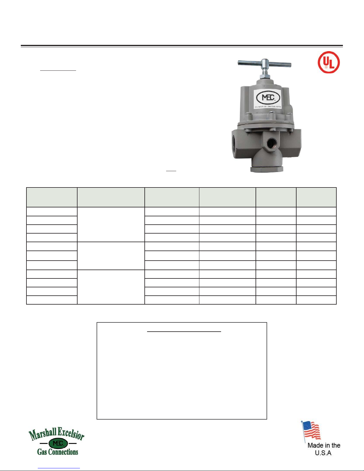
The MEGR-164 is a high capacity, pounds to pounds, industrial gas regulator. It is designed to conform to UL
Standard 144 for use with LP Gas. The maximum supply pressure is 400 PSIG. The maximum output pressure
is printed on the regulator nameplate. This regulator is not intended for use in pressure applications below 3
PSIG. The operating temperature range is -40° to +200° F.
INSTALLATION:
Ensure all gas lines are free from dirt and scale. Shut off the gas. The MEGR-164 can be mounted at any angle
without affecting operation. Install the regulator as close as possible to the instrument that it is to supply. Avoid
using undersized fittings that will limit the flow through the regulator and cause downstream pressure drop.
Apply a minimum amount of pipe compound to the male threads of the inlet and outlet piping. The words "IN"
and "OUT" are cast into the body of the regulator to indicate the direction of flow. The regulator must be oriented
in the correct flow direction or internal damage to the regulator may occur. The two 1/4" NPT gauge ports
marked "GA" can also be used as optional output ports, but with decreased flow delivery. Before putting the
regulator into service for the first time, relieve compression on the range spring by turning the "T" handle counter
clockwise. After gas is applied to the regulator, check installation to ensure that there is a leak tight seal. To
operate, turn the "T" handle slowly in a clockwise direction until the required downstream pressure is obtained.
CAUTION:
The MEGR-164 is a non-relieving regulator and thus cannot exhaust excess pressure at the regulator. In
order to establish an accurate output pressure it may be necessary to cycle the downstream flow or to
set the regulator at a slight flow.
MAINTENANCE:
Because the MEGR-164 is assembled and tested at the factory to conform to UL Standard 144, any
maintenance or repair should be in accordance with this listing as well as any other applicable regulations.
Regulator parts showing wear should be replaced as necessary. The procedure below describes how to
disassemble the MEGR-164 for parts replacement and inspection. Assembly is the reverse of this procedure.
1. Turn the adjustment screw counterclockwise to
remove springtension.
2. Loosen the six build screws and separate the
bonnet from the body.
3. Remove the spring guide andspring.
4. Unscrew the diaphragm assembly from the
pintle assembly.
5. Loosen, by turning counterclockwise, and
remove the O-Ring and bottom plug.
6. Remove the pintle spring and pintle
assembly.
Form #910 Rev C

MEGR-164 Series
HIGH PRESSURE REGULATORS
MEGR-164 SERIES
APPLICATION:
The MEGR-164 Series adjustable high-pressure regulators offer a
wide selection of available pressure ranges. High pressure
regulators are typically used to reduce tank pressure to an
intermediate pressure for use by another regulator. They may be
used as high pressure regulators on distribution systems when used
in conjunction with first-stage downstream regulators.
When equipped with an integral relief valve (MEGR-164SR Series),
the regulator may be used as a final-stage regulator on high
pressure systems. It may also be used as a first-stage regulator when
set at 10 PSIG (0,69 bar) or less. The 1/4”-inch FNPT tapped side
outlet can be used to install a pressure gauge or a hydrostatic relief
valve. This series contains brass materials that are not compatible
with anhydrous ammonia service.
Part No.
Description
Outlet Pressure Setting,
PSIG
Outlet Adjustment Range,
PSIG
BTU/H *
LPG @ 60 PSI
Inlet
BTU/H *
LPG @ 100 PSI
Inlet
MEGR-164/33
1/2” FNPT x 1/2” FNPT
Adjustable High Pressure
Regulator
10
0-30
6,098,000
6,800,000
MEGR-164/35
20
0-30
6,400,000
8,335,000
MEGR-164/36
40
0-60
6,100,000
9,145,000
MEGR-164/222
50
0-125
4,900,000
7,225,000
MEGR-164SR/21
1/2” FNPT x 1/2” FNPT
Adjustable High Pressure
Regulator w/ Internal
Relief Valve
10
0-15
4,675,000
7,825,000
MEGR-164SR/22
15
0-30
3,050,000
4,125,000
MEGR-164SR/23
20
0-30
3,405,000
4,755,000
MEGR-164-6/33
3/4” FNPT x 3/4” FNPT
Adjustable High Pressure
Regulator
10
0-30
9,150,000
10,875,000
MEGR-164-6/35
20
0-30
10,105,000
12,400,000
MEGR-164-6/36
40
0-60
9,960,000
13,415,000
MEGR-164-6/222
50
35-100
4,575,000
11,890,000
Note: 1” model also available (MEGR-164-8). Please contact factory for more information.
* BTU/H Capacity @ 20% Droop
* Other configurations and materials available upon request.
For Your Local Marshall Excelsior Distributor Call 269-789-6700,
Fax 269-781-8340 or E-mail: sales@marshallexcelsior.com
www.marshallexcelsior.com
MEGR-164 SPECIFICATIONS:
Type: Adjustable/PSI
Max. Inlet Pressure: 250 PSI
Inlet Connection: 1/2” FNPT or 3/4” FNPT
Outlet Connection: 1/2” FNPT or 3/4” FNPT
Exterior Finish: Gray Urethane
Regulator Spring: Steel
Stem Guide/Disk Holder: Stainless Steel
Diaphragm: Fabric Reinforced Nitrile (NBR)
or Fabric Reinforced Viton (V)
Bonnet / Body Material: Cast Aluminum
Vent: Non-Relieving
This manual suits for next models
11
Table of contents