Instruction Manual DSR digital regulator - rev. 05 - pag. 6
2. Connections
The digital regulator connections depend on the application and excitation system.
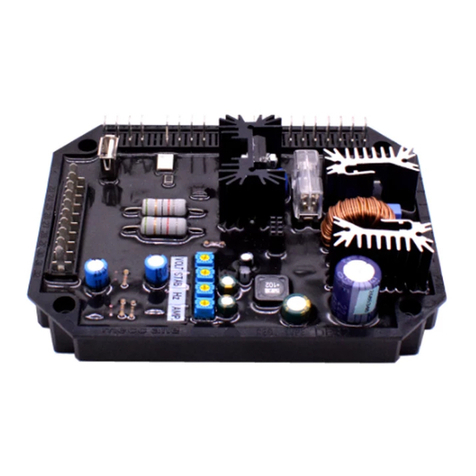
Figure 1 shows the functional aspect of the connection points to the regulator.
3. Terminals
Figures 2 show the connection terminals; the connections must be made using cables having a minimum
diameter :
•
for power cables on terminals 1, 2, 3 and 9 (Exc-, Aux/exc+, Aux): 1,5 mm²
•
for signal cables: 0,5 mm²
4. DSR connections for typical applications
Drawings SCC0059/02, SCC0060/02, SCC0061/02, SCC0062/02, SCC0063/02, SCC0064/02 show DSR
regulator connections for typical applications.
Drawing SCC0059/02 shows the connection to Series 3 alternators with 6 terminals.
Drawing SCC0060/02 shows the connection to Series 3 alternators with 12 terminals.
Drawing SCC0061/02 shows the connection to alternators with 6 terminals with reference from 140V to
280V. Drawing SCC0062/02 shows the connection to alternators with 12 terminals, with reference to the
half phase from 70V to 140V (for example series ECO28-38, ECO40-1S, ECO40-2S, ECO40-1L, ECO40-
2L and ECO40VL)
Drawing SCC0063/02 shows the connection to alternators with 12 terminals, in series star connection or
series delta connection, with reference to the entire phase from 140V to 280V (for example series ECO28-
38, ECO40-1S, ECO40-2S ECO40-1L, ECO40-2L and ECO40VL)
Drawing SCC0064/02 shows the connection to alternators with 12 terminals, with reference to the half
phase from 140V to 280V (for example ECO40-3S, ECO40-1,5L, Series ECO43-46)
5. Setting up the regulator
Selection of the sensing scale takes place directly according to the connection on the power terminal
board; additional settings can be made with 4 trimmers (VOLT, STAB, AMP and Hz) and 3 jumpers
(50/60Hz, JP1 and JP2); the output voltage can also be set with an external analogical or numeric signal;
additional settings, can be made by modifying the 23 parameters stored in a non volatile integrated memo-
ry.
5.1 Alternator voltage signals
Terminals 4, 5, 6, 7 and 8 of connector CN1 are used for voltage sensing.
5.2 Calibrating sensing
A supplementary calibration may be necessary to compensate for any existing tolerances on analogical
voltage acquisition channels; in this case follow the procedure illustrated below:
1. Write 16384 on location 19
2. Disable the Trimmers (from the Configuration Menu)
3. Disable Vext (from the Configuration Menu)
4. Set the adjustment on the average or effective value (from the Configuration Menu)
5. Measure the voltage with a suitable instrument for the type of adjustment made (average value or rms
value)
6. Set the value at location 5 (or 6) until the voltage value, measured with the instrument, reaches 210 V (if
the sensing is connected to terminals 4 or 5) or 105V (if the sensing is connected to terminals 6 or 7),
keeping in mind that an increase in the value set provokes an increase in adjusted voltage and vicever-
sa.
7. In order to ensure that the value of voltage (available also at location 36) is the same as the value
measured at point 6, calibrate the data at location 7, reading the value in the first “STATUS” box (ref.
DSR Terminal Software).
8. Enable the trimmers you want to be active (from the Configuration Menu)
9. Enable Vext (from the Configuration Menu) if you want to be active
5.3 50/60 Signal
A jumper is located on the 50/60 input (connector CN1, terminals 12 and 13); if enabled from the
Configuration Menu, it provokes the commutation of the underspeed protection threshold from 50·(100%-
Hz%) to 60·(100%-Hz%), where Hz% represents the position relative to the Hz trimmer or the
percentage value entered in location 21 (where 10% corresponds to 16384).
An error in connection may have serious consequences for the unit.
Carefully check to make sure that all connections are precise and in accordance with the atta-
ched drawings, before turning on the power.


