CDVI KCIN User manual

KCIN
Group Products
1, 2 or 3 relays
Range: Digicode® /
INSTALLATION MANUAL
1, 2 eller 3 relän
Sortiment: Digicode®
INSTALLATIONSMANUAL
SVENSKA
SE
ENGLISH
EN

2
147
124 55
Remote electronics included with the KCIN
-20° C to +70°C
Degree of protection IP52
FCC certication CFR
47 Part 15 compliance
Certication CE
Certication R&TTE
1] PRODUCT PRESENTATION
Stainless steel
permanent or timed.
(in plastic enclosure).
1 to 99 seconds,
Operating voltage:
12 to 24V AC and 12 to 48V DC.
Consumption (when 3 relay outputs activated.
and keypad illuminated)
- At 12 V AC: In standby 90 mA,
- At 24 V AC: In standby 46 mA,
- At 12 V DC: In standby 100 mA,
- At 24 V DC: In standby 55 mA,
- At 48 V DC: In standby 30 mA.
Input voltage: 12 V to 24 Vac or 12 V to 48 Vdc.
KCIN
Illuminated weatherproof Keypad with Remote Electronics 1, 2 or 3 relays
INSTALLATION MANUAL
2cdvi.se
cdvigroup.com
-25° C to +70°C
Suitable for use in marine environments
IP67
Certication CE
HIGH RESISTANCE
TO VANDALISM
The KCIN is a rugged stainless steel
keypad with soft blue backlighting.
Ideal for harsh environments, the KCIN
has 1 relay output. The keypad comes
with a remote electronics which makes
it a high security device.

33
cdvi.se
cdvigroup.com
Remote
electronic
mounting
plate
Wire
sealed
cap
Varistor
Diax® screws
(M5x35) Diax®
Plastic
anchor
S
crew
(M4x30)
Brass
anchor
Remote
electronic 1 2 - - - 2 2 -
KCIN - - 1 2 1 2 2 2
3] MOUNTING KIT
2] NOTES AND RECOMMENDATIONS
CABLE
- The distance between the KCIN
and the remote electronic can not exceed
more than 10 meters.
- Make sure that the cable is not near
by a high voltage cable (ex: 230 V AC).
Recommended cable between
The KCIN and the remote electronic
2-pair cables (4 wires) SYT1 8/10ths.
Recommended power supplies
suitable for the KCIN
- ARD12 (230V input)
- BS60 (230V input)
Mounting recommendations
Mount the keypad on a at surface to avoid
any vandalism and to insure the best mounting.
Security advice
- For security reasons, change
the factory default master code.
- When selecting a master code and user code
avoid simple codes (example : 3 4 5 6 7).
Back EMF protection
To secure the system from back electromagnetic
elds do not forget to mount the varistor
in parallel on the lock terminal.
KCIN
Illuminated weatherproof Keypad with Remote Electronics 1, 2 or 3 relays
INSTALLATION MANUAL

1
4
2
5
3
44cdvi.se
cdvigroup.com
4] MOUNTING INSTRUCTIONS
Once you have made sure that the mounting kit is complete and that you prepared the cables
of the KCIN keypad and its remote electronic then you can proceed and mount the product.
Make sure that you have all the appropriate tools (drill, screw drivers and a meter tape...)
and follow the mounting instructions of for the KCIN keypad and for the remote electronic.
Verify the distance between the
KCIN keypad and its remote
electronic (refer to page 3 ´Notes
and Recommendations). Place the
back plate of the KCIN on the wall
and the bracket of the remote
electronic then mark with a pen
the hole location then drill the 2
mounting holes (drill bit Ø 5 mm
and 35 MM hole depth) and the
hole wiring access.
Insert the 2 plastic anchors
in the holes. Then mount the
bracket of the remote electro-
nics with the M4x30 screws.
Slide the box from up to down
on the bracket.
Insert the 2 plastic anchors
in the holes. Place the back
plate of the KCIN and screw
on the wall using the supplied
(M4x30) mounting screws.
Insert the cable in the remote
electronic and wire the cable to
the terminals. Donít forget to
install the varistor on the lock
(refer to page 3 ´Notes and Re-
commendations‘).
Mount the KCIN keypad
on the wall with the M5x35
DIAX® screws.
KCIN
Illuminated weatherproof Keypad with Remote Electronics 1, 2 or 3 relays
INSTALLATION MANUAL

KCIN
Illuminated weatherproof Keypad with Remote Electronics 1, 2 or 3 relays
INSTALLATION MANUAL
5] WIRING DIAGRAM : KCIN 1-RELAY OUTPUT
Remote electronics
P3 jumper allows to the
user to modify its own
Pin code. To enable this
feature put the jumper
on. (see Programming
section in the instruction
manual)
P2 jumper resets the key-
pad to factory default
values. Remove the power
from the keypad then put
the jumper.
(see Programming section
in the instruction manual)
Power supply
12 to 24VAC
or 12 to 48VDC
H (Open) KCIN
Keypad mode
H (Closed) KCIN
Request-to-Enter
mode
Power supply
According to lock
specications
White
Brown
Green or blue
Varistor
Relay
1
P2
P3
Request-to-Exit inputs
P1 request-to-exit input activates relay 1.
P2 request-to-exit input activates relay 2.
Latch or toggled output.
H input can be used with
a timer to enable free access
by pressing on any digit key
on the keypad.
When the contact is open
then the request-to-enter is disabled.
When the contact is closed then press
any key on the keypad to enter.
Outputs Description
V
Input voltage 12V to 24V ac or 12V to 48V dc
V
Input voltage 12V to 24V ac or 12V to 48V dc
R1 N/C contact relay 1
C1 Common relay 1
T1 N/O contact relay 1
P1 Request-to-exit input relay 1
MCommon of input
HTimer Contact
+White wire keypad
-Brown wire keypad
EGreen or Blue wire (illumination)
5
cdvi.se
cdvigroup.com
Fail safe lock
Fail secure lock

6
6] WIRING DIAGRAM KCIN 2-RELAY OUTPUTS
Request-to-Exit inputs
P1 request-to-exit input activates relay 1.
P2 request-to-exit input activates relay 2.
Latch or toggled output.
H input can be used with
a timer to enable free access
by pressing on any digit key
on the keypad.
When the contact is open
then the request-to-enter is disabled.
When the contact is closed then press
any key on the keypad to enter.
Remote electronics
P3 jumper allows
to the user to modify
its own Pin code.
To enable this feature
put the jumper on.
(see Programming
section in the
instruction manual)
P2 jumper resets the key-
pad to factory default
values. Remove the power
from the keypad then put
the jumper.
(see Programming section
in the instruction manual)
KCIN
Illuminated weatherproof Keypad with Remote Electronics 1, 2 or 3 relays
INSTALLATION MANUAL
Power supply
12 to 24VAC
or 12 to 48VDC
H (Open)
KCIN Keypad mode
H (Closed)
KCIN Request-to-
Enter mode
Power supply
According to lock
specications
White
Brown
Green or blue
Varistor
P2
P3
Relay
1
Relay
2
Outputs Description
V
Input voltage 12V to 24VAC or 12V to 48VDC
V
Input voltage 12V to 24VAC or 12V to 48VDC
R1 N/C contact relay 1
C1 Common relay 1
T1 N/O contact relay 1
R2 N/C contact relay 2
C2 Common relay 2
T2 N/O contact relay 2
P1 Request-to-exit input relay 1
MCommon of inputs
P2 Request-to-exit input relay 2
HTimer Contact
+White wire from keypad
-Brown wire from keypad
EGreen or Blue wire (illumination)
6cdvi.se
cdvigroup.com
Fail safe lock
Fail secure lock

7
Remote electronics
P3 jumper allows
to the user to modify
its own Pin code.
To enable this feature
put the jumper on.
(see Programming
section in the
instruction manual)
P2 jumper resets the key-
pad to factory default
values. Remove the power
from the keypad then put
the jumper.
(see Programming section
in the instruction manual)
7] WIRING DIAGRAM KCIN 3-RELAY OUTPUTS
Request-to-Exit inputs
P1 request-to-exit input activates relay 1.
P2 request-to-exit input activates relay 2.
Latch or toggled output.
H input can be used with
a timer to enable free access
by pressing on any digit key
on the keypad.
When the contact is open
then the request-to-enter is disabled.
When the contact is closed then press
any key on the keypad to enter.
KCIN
Illuminated weatherproof Keypad with Remote Electronics 1, 2 or 3 relays
INSTALLATION MANUAL
Power supply
12 to 24VAC
or 12 to 48VDC
H (Open)
KCIN Keypad mode
H (Closed)
KCIN Request-to-
Enter mode
Power supply
According to lock
specications
White
Brown
Green or blue
Varistor
P2
P3
Relay
1
Relay
2
Relay
3
Outputs Description
V
Input voltage 12V to 24VAC or 12V to 48VDC
V
Input voltage 12V to 24VAC or 12V to 48VDC
R1 N/C contact relay 1
C1 Common relay 1
T1 N/O contact relay 1
R2 N/C contact relay 2
C2 Common relay 2
T2 N/O contact relay 2
R3 N/C contact relay 3
C3 Common relay 3
T3 N/O contact relay 3
P1 Request-to-exit input relay 1
MCommon of inputs
P2 Request-to-exit input relay 2
HTimer Contact
+ White wire from keypad
-Brown wire from keypad
EGreen or Blue wire (illumination)
7
cdvi.se
cdvigroup.com
Fail safe lock
Fail secure lock

8
A. RESET MASTER CODE
AND USER CODES
1.
Enter the master code twice
(1 2 3 4 5 default value master code).
2 beeps are emitted to conrm
entry in programming mode.
2.
Press
A6 to reset the Master Code
and the User codes.
One beep is emitted. Press on A
and B to conrm reset of all memory
of the keypad. Wait for two beeps.
The master code is restored
to its default value 1 2 3 4 5
and all the User codes are deleted
from the keypad. Once the reset
is completed then the keypad returns
to a stand-by operating mode.
OR
1. Cut the power. Put the jumper on P2.
2. Put the power back.
Wait approximately 3 seconds.
Two beeps are emitted to conrm reset
of the keypad. Remove P2 jumper.
The master code is restored to its default
value 1 2 3 4 5 and all the User codes
are deleted from the keypad.
B. SETTING CODE LENGTH
1. Enter the master code twice.
(1 2 3 4 5 default value master code).
2 beeps are emitted to conrm
entry in programming mode.
2. Press A4 to program the code length.
One beep is emitted. Press 4 or 5
for the digit code.
One beep is emitted
to conrm programming of the code length.
3.
Press
A5 to modify the master code.
One beep is emitted. Enter the new 4
or 5-digit master code. One beep is
emitted to conrm programming
of the new master code.
4. Press B to exit from
programming mode.
2 beeps are emitted to conrm that the key-
pad is in stand-by operating mode.
4 beeps indicate a data computing error.
C. CHANGING THE MASTER CODE
The master code is used only
to enter in programming mode.
1. Enter the master code twice.
(1 2 3 4 5 default value master code).
2 beeps are emitted to conrm
entry in programming mode.
2.
Press
A5 to modify the master code.
One beep is emitted. Enter the new 4
or 5 digit master code. One beep
is emitted to conrm that the master
code is programmed.
3. Press B to exit from
the programming mode.
2 beeps are emitted to conrm that the key-
pad is in stand-by operating mode.
Default values
- Without codes.
- Illumination time: 10 seconds.
- Relay release time: 1 second.
- Code length: 5-digit.
- Master Code: 1 2 3 4 5.
- Programming security time
:
120 secondes.
-
Code length for sub master code:
Version 1 relay (Group 1) =
A and B,
Version 2 relays (Group 2) =
1 and 3
Version 3 relays (Group 3) =
4 and 6.
Audible signal:
The buzzer indicates different audible
signals. It can be turned off by cutting
the ST1 wire on the remote controller
1 short beep: Keypad powered
1 long beep: Data computing
in programming or access granted
2 short beeps: Enter or Exit
from programming
4 short beeps:
Data computing error.
Code length
The master code and the User codes
can be of 4 or 5-digit in length.
All the keypad keys can be used
to program a code. The master code
and the Pin code can be of 4 or 5-digit
code. The master code CAN NOT be used
as a PIN code (User Pin code).
To delete a specic User pin Code replace
it by 0000 if code length is 4-digit format
or replace it by 00000 if the code
is in 5-digit format.
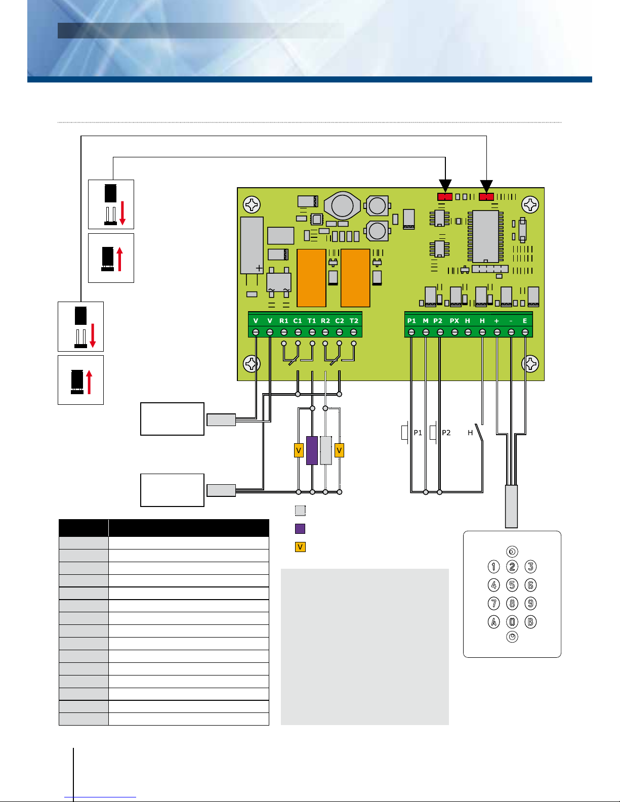
P2 jumper:
Reset master code and user codes
P3 jumper:
modication of individual
code by the user
KCIN
Illuminated weatherproof Keypad with Remote Electronics 1, 2 or 3 relays
INSTALLATION MANUAL
8cdvi.se
cdvigroup.com

9
D. ADDING, CHANGING
OR DELETING A USER CODE
Group 1: From address 00 to address 99,
relay output 1
1. Enter the master code twice
(1 2 3 4 5 default value master code).
2 beeps are emitted to conrm entry
in programming mode.
2. To add a user code, enter the user
location (from 00 to 99).
If the user location is free 1 beep
is emitted, enter the 4 or 5-digit
User code.
3. To change a user code enter
the user location.
4 beeps are emitted to indicate that
user location is already programmed.
Enter a new 4 or 5-digit code.
A beep is emitted to conrm the new
user code.
4. To delete a User code enter
the user location.
4 beeps are emitted.
Press 0 0 0 0 0 in 5-digit length code
or 0 0 0 0 in 4-digit length code.
A beep is emitted to conrm the new
user code.
NOTE: If the Pin code is already programmed
or is identical to the master code,
then 4 beeps are emitted.
Press B to exit from the programming
mode. 2 beeps are emitted to conrm
that the keypad is in stand-by
operating mode.
E. TIME OUTPUTS
This section allows to program
the illumination time and the Relay
activation time.
1. Enter the master code twice
(1 2 3 4 5 default value master code).
2 beeps are emitted to conrm
entry in programming mode.
2. Press A0 to program the key-in
keypad time and the keys lit time.
1 beep is emitted. Enter the time in 10th
of second – 10 for 10 seconds up to 99
for 99 seconds the backlighting dims
10 seconds after the last keypress
or switches off after entering a valid
code. Press 00 for permanent
illumination keys.
One beep is emitted to validate the time.
3. Press A1 to program relay 1
output time (door release time).
1 beep is emitted. For a latched output
enter the time in seconds – 01 for 1
second up to 99 for 99 seconds.
Press 00 for a toggled output.
One beep is emitted to validate the time.
4. Press B to exit from
programming mode.
2 beeps are emitted to conrm that the key-
pad is in stand-by operating mode.
4 beeps indicate a data computing error.
F. RESET MASTER CODE
On stand-by operating mode,
put a jumper on P2.
Wait 1 second and then remove
the jumper. One beep is emitted.
The master code is restored
to its default value 1 2 3 4 5 in 5-digit
code and 1 2 3 4 in 4-digit code.
G. CHANGING THE CODE
BY A USER
To authorize a user to modify its own
User code put a jumper on P3
(to disable the feature remove the jumper).
1. Enter the old user code.
The relay is activated and a beep
is emitted.
2. Enter the 2-digit sub master code
(default sub master code A and B).
A beep is emitted to authorise
the modication.
3. Enter the new user code.
2 beeps are emitted to conrm
the new code.
4. Check the new user code to be sure
of the modication.
H.
SETTING A SUB MASTER CODE
The Sub Master code allows the user
to change its own code without entering
in programming mode. For security
reasons the code need to be changed
periodically. This feature makes it easier
and faster to change its code.
KCIN
Illuminated weatherproof Keypad with Remote Electronics 1, 2 or 3 relays
INSTALLATION MANUAL
9
cdvi.se
cdvigroup.com

10
1. Enter the master code twice
(1 2 3 4 5 default value master code).
2 beeps are emitted to conrm entry
in programming mode.
2. Press A7 to program a sub master
code for the user individual Pin
code modication.
One beep is emitted. Enter the new
2-digit sub master code. One beep
is emitted to conrm programming
of the sub master code.
3. Press B to exit from
the programming mode.
2 beeps are emitted to conrm
that the keypad is in stand-by
operating mode.
I. Audible Feedback
The audible signal is enabled
in programming mode
and when the relay is energised
after a valid code.
To enable the audible feedback
on a key press:
1. Enter the master code twice
(1 2 3 4 5 default value master code).
2 beeps are emitted to conrm entry
in programming mode.
2. Press AA.
One beep is emitted. Press 0 to disable
the audible signal during a keypress.
Press 1 to enable the audible signal
during a keypress. One beep conrms
the new setting.
3. Press B to exit from programming.
2 beeps are emitted to conrm exit
from programming mode.
J. OPTIONAL KCIN 2 AND KCIN 3
PROGRAMMING INSTRUCTION
Programming instructions are the same
as for the KCIN keypad with 1
relay output.
KCIN 2: 2 relay outputs N/O
and N/C contacts 8A @ 250V~.
Group 1: From user location 00
to user location 59 to activate relay 1.
Group 2: from user location 60
to user location 99 to activate relay 2
Release Time of relay2 enter A2,
sub master code enter A8
(default values 1 and 3).
KCIN 3: 3 relay outputs N/O
and N/C contacts 8A @ 250V~.
Group 1: from user location 00
to user location 59 to activate relay 1.
Group 2: from user location 60
to user location 79 to activate relay 2.
Group 3: from user location 80
to user location 99 to activate relay 3.
Release time for relay 3 enter A3
sub master code enter A9
(default values 4 and 6).
KCIN
Illuminated weatherproof Keypad with Remote Electronics 1, 2 or 3 relays
INSTALLATION MANUAL
10 cdvi.se
cdvigroup.com

11
User
location
Code Name
00
01
02
03
04
05
06
07
08
09
10
11
12
13
14
15
16
17
18
19
20
21
22
23
24
25
26
27
28
29
30
31
32
33
User
location
Code Name
34
35
36
37
38
39
40
41
42
43
44
45
46
47
48
49
50
51
52
53
54
55
56
57
58
59
60
61
62
63
64
65
66
67
User
location
Code Name
68
69
70
71
72
73
74
75
76
77
78
79
80
81
82
83
84
85
86
87
88
89
90
91
92
93
94
95
96
97
98
99
KCIN 1 Relays (1 output)
Relay 1 : From user location
00 to 99.
KCIN 2 Relays
Relay 1 : From 00 to 59,
Relay 2 : From 60 to 99.
KCIN 3 Relays
Relay 1 : From 00 to 59,
Relay 2 : From 60 to 79,
Relay 3 : From 80 to 99.
REMINDER
KCIN
Illuminated weatherproof Keypad with Remote Electronics 1, 2 or 3 relays
INSTALLATION MANUAL
11
cdvi.se
cdvigroup.com

12
KCIN
Illuminated weatherproof Keypad with Remote Electronics 1, 2 or 3 relays
INSTALLATION MANUAL
7] NOTES
12 cdvi.se
cdvigroup.com

13
147
124 55
13
cdvi.se
cdvigroup.com
1] PRODUKTSPECIFIKATION
konstant eller tidsinställd.
Dimensioner (L x B x H) :
110 x 85 x 14 mm.
Strömförsörjning :
- 12 V till 24 V AC
- 12 V till 48 V DC
Strömförbrukning (med tre aktiverade
relän och belyst knappsats :
- Vid 12 V AC: I standby-läge 90 mA
- Vid 24 V AC: I standby-läge 46 mA
- Vid 12 V DC: I standby-läge 100 mA
- Vid 24 V DC: I standby-läge 55 mA
- Vid 48 V DC: I standby-läge 30 mA
KCIN
Vattentätt kodlås med bakgrundsbelysning i delat montage
INSTALLATIONSMANUAL
Levereras med styrenhet
-25° C till +70°C
Miljötålighetsprov: salttålighet
IP67
CE godkänd
-20° C till +70°C
IP52
CE godkänd
FCC certierad
R&TTE certierad
HIGH RESISTANCE
TO VANDALISM

14
3] MONTERINGSSATS
2] INFORMATION OCH REKOMMENDATIONER
Kablage
- Avståndet mellan KCIN kodlås och styrenheten
bör inte överstiga 50 m.
- Se till att kablarna inte dras nära
högspänningsledningar (ex: 230 V AC).
Rekommenderad kabel mellan KCIN
och styrenheten
En fyrledare (fyra trådar) SYT1 0,8 mm.
Rekommenderad strömförsörjning
- ARD12
- BS60
Montering
Fäst KCIN på en plan yta för att förhindra
vandalisering och för att erhålla bästa möjliga
montering.
Säkerhets tips
- Av säkerhetsskäl bör den förinställda,
standardiserade masterkoden ändras.
-
Vid val av masterkod och användarkod, undvik
sekventiella koder (ex: 3 4 5 6 7).
Rekommenderad installation
För att säkra systemet från strömspikar glöm
inte att montera varistorn parallellt med låset.
Förse elslutblecket (elektromagneten) med
varistor om det saknas. Om kodlåset styr
mer än ett elslutbleck, ska varje lås förses
med en varistor. Varistorn kontrollerar den
överspänning som produceras av magnetspolen
- backspänningsspikar. Det rekommenderas att
använda en separat spänningskälla när man styr
ett elektromagnetiskt lås.
KCIN
Vattentätt kodlås med bakgrundsbelysning i delat montage
INSTALLATIONSMANUAL
14 cdvi.se
cdvigroup.com
Monte-
rings-
platta för
styrenhet
Packning
Varistor
Diax®
skruv
(M5x35)
Diax®
fastnyckel
Plast-
plugg
Monte-
ringsskruv
(M4x30)
Metall-
plugg
Styrenhet 1 2 - - - 2 2 -
KCIN - - 1 2 1 2 2 2

1
4
2
5
3
15
KCIN
Vattentätt kodlås med bakgrundsbelysning i delat montage
INSTALLATIONSMANUAL
4] MONTERINGSINSTRUKTIONER
Kontrollera att monteringssatsen är komplett, och att du förberett kablarna till KCIN
kodlås och styrenhet innan monteringen påbörjas. Försäkra dig om att du har rätt verktyg
tillgängliga (borr, skruvmejsel, måttstock mm) och följ sedan monteringsanvisningarna för
KCIN kodlås och styrenhet.
Kontrollera avståndet mellan
KCIN kodlås och styrenhet
(Se sid 14 «Information och
rekommendationer»). Sätt
kodlåset och styrenhetens
monteringsplatta mot väggen
och markera hålens placering
med en penna. Borra sedan
två monteringshål och hål för
kabeln (Ø 5 mm och min. djup
= 35 mm) .
Sätt plastpluggar i de borrade
hålen för styrenheten.
Skruva fast monteringsplattan
med M4x30 skruvar.
För styrenheten uppifrån och
ner för att haka fast den på
monteringsplattan.
Sätt metallpluggar i de borrade
hålen där kodlåset skall fästas.
Trä in KCIN-kabeln i
styrenheten och anslut med
kopplingsplintarna.
Glöm inte att installera varistorn
(Se sid 14 «Information och
rekommendationer»).
Trä KCIN-kabeln genom det
borrade kabelhålet.
Skruva fast kodlåset med de
bifogade Diax® skruvarna med
hjälp av Diax® nyckeln.
15
cdvi.se
cdvigroup.com

5] KOPPLINGSSCHEMA KCIN 1 RELÄUTGÅNG
Styrenhet
P3: Låter användaren
själv ändra sin
PIN-kod.
Byglas för att
aktivera funktionen.
(Se avsnittet om
«Programmering»)
P2: Total återställning,
kodlåsets alla
inställningar återställs till
fabriksinställningarna.
Slå av strömmen och bygla
sedan för att aktivera
funktionen. (Se avsnittet
om «Programmering»)
Ingång för externa öppnaknappar
Detta är en normalt öppen krets som fungerar
vid aktivering av relä 1. Denna funktion är
speciellt användbar för att öppna dörr/grind/
port inifrån utan knappsats.
Ingång P1 aktiverar relä 1.
Timeringång H (om ansluten) gör det möjligt
att använda alla knappar på knappsatsen som
öppnaknappar. Om timerkontakten är öppen,
används inga knappar som öppnaknapp. Vill
man ha helt öppet under till exempel dagtid
skall timern anslutas mellan C1 och T1, se
kopplingsschema.
H (Öppen)
KCIN kodlåsläge
H (Sluten)
Hela knappsatsen
fungerar som
öppnaknappar
Inspänning
12 till 24VAC eller
12 till 48VDC Omvänd funktion/
magnet
Rättvänd funktion/
elslutbleck
Varistor
KCIN
Vattentätt kodlås med bakgrundsbelysning i delat montage
INSTALLATIONSMANUAL
Plint Beskrivning
VInspänning 12-24 V AC eller 12-48 V DC
R1 N/C kontakt (Omvänd funktion), relä 1
C1 Gemensam, relä 1
T1 N/O kontakt (Rättvänd funktion), relä 1
P1 Ingång för extern öppnaknapp, relä 1
MGemensam, ingång
HTimerkontakt
+Vit kabel från knappsats
-Brun kabel från knappsats
EGrön eller blå kabel (bakgrundsbelysning)
cdvi.se
cdvigroup.com
Relä
1
16
P2
P3
Vit
Brun
Grön eller blå

17
Vit
Brun
Grön eller blå
6] KOPPLINGSSCHEMA KCIN 2 RELÄUTGÅNGAR
Ingång för externa öppnaknappar
Detta är en normalt öppen krets som fungerar
vid aktivering av relä 1. Denna funktion är
speciellt användbar för att öppna dörr/grind/
port inifrån utan knappsats.
Ingång P1 aktiverar relä 1.
Ingång P2 aktiverar relä 2.
Timeringång H (om ansluten) gör det möjligt
att använda alla knappar på knappsatsen som
öppnaknappar. Om timerkontakten är öppen,
används inga knappar som öppnaknapp. Vill
man ha helt öppet under till exempel dagtid
skall timern anslutas mellan C1 och T1, se
kopplingsschema.
Styrenhet
P3: Låter användaren
själv ändra sin
PIN-kod.
Byglas för att
aktivera funktionen.
(Se avsnittet om
«Programmering»)
P2: Total återställning,
kodlåsets alla
inställningar återställs till
fabriksinställningarna.
Slå av strömmen och bygla
sedan för att aktivera
funktionen. (Se avsnittet
om «Programmering»)
H (öppen)
KCIN kodlåsläge
H (sluten)
Hela knappsatsen
fungerar som
öppnaknappar
Inspänning
12 till 24VAC eller
12 till 48VDC Omvänd funktion/
magnet
Rättvänd funktion/
elslutbleck
Varistor
KCIN
Vattentätt kodlås med bakgrundsbelysning i delat montage
INSTALLATIONSMANUAL
Plint Beskrivning
VInspänning 12-24 V AC eller 12-48 V DC
R1 N/C kontakt (Omvänd funktion), relä 1
C1 Gemensam, relä 1
T1 N/O kontakt (Rättvänd funktion), relä 1
R2 N/C kontakt (Omvänd funktion), relä 2
C2 Gemensam, relä 2
T2 N/O kontakt (Rättvänd funktion), relä 2
P1 Extern öppnaknapp, relä 1
MGemensam ingång
P2 Extern öppnaknapp, relä 2
HTimerkontakt
+Vit kabel
-Brun kabel
EGrön eller blå kabel (bakgrundsbelysning)
Relä
1
Relä
2
17
cdvi.se
cdvigroup.com
P2
P3

18
P2
P3
Vit
Brun
Grön eller blå
Styrenhet
P3: Låter användaren
själv ändra sin
PIN-kod.
Byglas för att
aktivera funktionen.
(Se avsnittet om
«Programmering»)
P2: Total återställning,
kodlåsets alla
inställningar återställs till
fabriksinställningarna.
Slå av strömmen och bygla
sedan för att aktivera
funktionen. (Se avsnittet
om «Programmering»)
7] KOPPLINGSSCHEMA KCIN 3 RELÄUTGÅNGAR
Ingång för externa öppnaknappar
Detta är en normalt öppen krets som
fungerar vid aktivering av relä 1. Denna
funktion är speciellt användbar för att öppna
dörr/grind/port inifrån utan knappsats.
Ingång P1 aktiverar relä 1.
Ingång P2 aktiverar relä 2.
Timeringång H (om ansluten) gör det möjligt
att använda alla knappar på knappsatsen
som öppnaknappar. Om timerkontakten
är öppen, används inga knappar som
öppnaknapp. Vill man ha helt öppet under
till exempel dagtid skall timern anslutas
mellan C1 och T1, se kopplingsschema.
H (öppen)
KCIN kodlåsläge
H (sluten)
Hela knappsatsen
fungerar som
öppnaknappar
Inspänning
12 till 24VAC eller
12 till 48VDC Omvänd funktion/
magnet
Rättvänd funktion/
elslutbleck
Varistor
KCIN
Vattentätt kodlås med bakgrundsbelysning i delat montage
INSTALLATIONSMANUAL
18 cdvi.se
cdvigroup.com
Plint Beskrivning
VInspänning 12-24 V AC eller 12-48 V DC
R1 N/C kontakt (Omvänd funktion), relä 1
C1 Gemensam, relä 1
T1 N/O kontakt (Rättvänd funktion), relä 1
R2 N/C kontakt (Omvänd funktion), relä 2
C2 Gemensam, relä 2
T2 N/O kontakt (Rättvänd funktion), relä 2
R3 N/C kontakt (Omvänd funktion), relä 3
C3 Gemensam, relä 3
T3 N/O kontakt (Rättvänd funktion), relä 3
P1 Extern öppnaknapp, relä 1
MGemensam ingång
P2 Extern öppnaknapp, relä 2
HTimerkontakt
+Vit kabel
-Brun kabel
EGrön eller blå kabel (bakgrundsbelysning)
Relä
1
Relä
2
Relä
3

19
P2
P3
A. Återställning av masterkod och
användarkoder
1. Knappa in masterkoden två gånger.
- Masterkoden default-värde : 1 2 3 4 5.
- Två pipsignaler bekräftar att man är i
programmeringsläget
.
2. Knappa in A6.
En pipsignal hörs.
3. Knappa in A och B
- Detta bekräftar återställningen av
kodlåsets hela minne.
- Vänta på två pipsignaler.
-
Masterkoden återställs till sitt
default-värde ( 1 2 3 4 5 )
och
alla användarkoder raderas från
knappsatsen.
- När återställningen är klar, återgår
knappsatsen till standby-läge.
1. Slå av strömmen och bygla P2.
Se bildöversikt på placering i avsnittet om
bygling på sidan 16-17-18.
2. Slå på strömmen igen.
- Vänta ca 3 sekunder.
- Två pipsignaler bekräftar att
knappsatsen är återställd.
- Ta bort byglingen från P2.
- Masterkoden återställs till sitt
default-värde ( 1 2 3 4 5 ) och
alla användarkoder raderas från
knappsatsen.
B. Ställa in kodlängden
1. Knappa in masterkoden två gånger.
- Masterkodens default-värde är 1 2 3 4 5.
- Två pipsignaler bekräftar att man är i
programmeringsläget.
2. Knappa in A4 för att programmera
kodlängden.
- En pipsignal hörs.
- Tryck 4 eller 5 för att ange önskad
kodlängd.
- En pipsignal bekräftar att kodlängden är
programmerad.
3.
Knappa in A5 för att ändra
masterkoden.
- En pipsignal hörs.
- Knappa in en ny 4- eller 5-siffrig
masterkod (fyra tecken om ni valt en
4-siffrig kod och fem tecken om ni valt
en 5-siffrig kod under A4 ovan).
- En pipsignal bekräftar att den nya
masterkoden är programmerad.
4. Tryck B för att lämna
programmeringsläget.
Två pipsignaler bekräftar att knappsatsen
är i standby-läge och redo att användas.
Standardvärden för KCIN :
Utan koder.
Tidsinställd belysning : 10 sek.
Reläslutningstid : 1 sekund.
Kodlängd : 5.
Masterkod : 1 2 3 4 5.
Tidsinställning för
programmering :
120 sekunder.
Undermasterkod :
- Version med 1 relä
(Relä 1) = A och B,
-
Version med 2 relän
(Relä 2) = 1 och 3
-
Version med 3 relän
(Relä 3) = 4 och 6.
Ljudsignal :
-
1 kort pipsignal =
Kodlåset är
spänningssatt.
- 1 lång pipsignal = Data sparat
i programmeringsläge eller
dörr öppnas.
- 2 korta pipsignaler =
Åtkomst till eller lämna
programmeringsläget.
- 4 korta pipsignaler =
Databehandlingsfel
.
Kodlängd :
Masterkoden och användarkoderna
kan vara 4- eller 5-siffriga. Alla
knappar på knappsatsen kan
användas för att programmera
en kod, även knapparna A och B.
Ändras kodlängden till 4-siffrig
blir även masterkoden 4-siffrig.
Masterkoden KAN INTE användas
som användarkod.
Koderna 0 0 0 0 0 och 0 0 0 0
kan endast användas för att ta
bort en användarkod. För att ta
bort en specik användarkod:
ersätt en 5-siffrig kod med 00000
och en 4-siffrig med 0000.
P2 bygling :
Total återställning.
P3 bygling :
Användaren kan ändra sin kod
själv.
KCIN
Vattentätt kodlås med bakgrundsbelysning i delat montage
INSTALLATIONSMANUAL
19
cdvi.se
cdvigroup.com

20
C. Ändra masterkoden
1. Knappa in masterkoden två gånger.
- Vid första användningen används
masterkodens default-värde : 1 2 3 4 5.
-
Två pipsignaler bekräftar att man är i
programmeringsläget.
2. Knappa in A5.
- En pipsignal hörs.
- Knappa in den nya 4- eller 5-siffriga
masterkoden.
- En pipsignal bekräftar att koden är
utbytt.
3. Tryck B för att lämna
programmeringsläget.
Två pipsignaler bekräftar att knappsatsen
är i standby-läge redo att användas.
D. Lägg till, ändra eller ta bort en
användarkod
-
Relä 1 : Från plats 00 till plats 99.
-
Relä 1 : Från plats 00 till plats 59,
Relä 2 : Från plats 60 till plats 99.
-
Relä 1 : Från plats 00 till plats 59,
Relä 2 : Från plats 60 till plats 79,
Relä 3 : Från plats 80 till plats 99.
1. Knappa in masterkoden två gånger.
-
Vid första användning används
masterkodens default-värde : 1 2 3 4 5.
- Två pipsignaler bekräftar att man är i
programmeringsläget.
2. Lägga till en användarkod :
Knappa in användarplats.
(mellan 00 och 99).
- Om användarplatsen är ledig, hörs en
pipsignal.
Knappa in den 4- eller 5-siffriga
användarkoden.
3. Ändra en användarkod :
Knappa in användarplats.
Fyra pipsignaler anger att
användarplatsen redan är programmerad.
- Knappa in en ny 4- eller 5-siffrig
kod. En pipsignal bekräftar den nya
användarkoden.
4. Ta bort en användarkod :
Knappa in användarplats.
Fyra pipsignaler hörs.
- Knappa in 0 0 0 0 0 för en 5-siffrig kod
eller 0 0 0 0 för en 4-siffrig kod.
- En pipsignal bekräftar att
användarkoden är raderad.
5.
Tryck B för att lämna
programmeringsläget.
Två pipsignaler bekräftar att knappsatsen
är i standby-läge redo att användas.
E.
Programmera tider
Avsnittet beskriver programmering av tider
för bakgrundsbelysning och reläaktivering.
1. Knappa in masterkoden två gånger.
- Vid första användningen används
masterkodens default-värde : 1 2 3 4 5.
- Två pipsignaler bekräftar att man är i
programmeringsläget.
2. Knappa in A0 för att programmera
knappsatsens belysningstid.
- En pipsignal hörs.
-
Knappa alltid in tiden med två siffror som
motsvarar belysningstiden i sekunder.
10 för 10 sekunder upp till 99 för
99 sekunder, eller knappa in 00 för en
konstant belysning av knapparna.
- Bakgrundsbelysningen lyser 10 sekunder
efter sista knapptryckningen eller släcks
efter det att en giltig kod matas in.
- En pipsignal bekräftar att tiden
programmerats.
3. Programmering av dörröppningstid.
Relä 1 : Knappa in A1.
Relä 2 : Knappa in A2.
Relä 3 : Knappa in A3.
- En pipsignal hörs.
- Om det är en låst utgång, matas tiden in
i sekunder.
01 för 1 sekund upp till 99 för 99
sekunder, eller knappa in 00 om det är
en bistabil utgång (reläet ändrar tillstånd
varje gång en korrekt användarkod
anges).
-
En pipsignal bekräftar programmerad tid.
4. Tryck B för att lämna
programmeringsläget.
Två pipsigneler bekräftar att knappsatsen
är i standby-läge redo att användas.
KCIN
Vattentätt kodlås med bakgrundsbelysning i delat montage
INSTALLATIONSMANUAL
20 cdvi.se
cdvigroup.com
Other manuals for KCIN
2
Table of contents
Languages:
Other CDVI Keypad manuals

CDVI
CDVI Krypto K3 Instruction Manual

CDVI
CDVI Galeo User manual

CDVI
CDVI PROMI E Quick start guide

CDVI
CDVI Galeo User manual

CDVI
CDVI GALEO 4.0 - Bluetooth User manual

CDVI
CDVI DGA User manual

CDVI
CDVI GALEO BT User manual

CDVI
CDVI Digicode PROFIL100EC User manual

CDVI
CDVI Digicode Series User manual

CDVI
CDVI CAA User manual