Mechan ISIS User manual

This information is designed to help suitably qualified
personnel install and operate Mechan Safety Switch
equipment. Before using this product, read this guide thoroughly along with
any relevant European and/or National standards e.g. Machinery Directive
89/392/EEC and it’s amendments, Provision and Use of Work Equipment
Regulations.
Further information can be obtained from Mechan Controls PLC
***** KEEP THIS GUIDE FOR FUTURE REFERENCE *****
CAUTION
DESCRIPTION
The ISIS safety system is a tamper resistant non-contact
safety switch system, suitable for use in most types of
machine guarding applications where guard locking is not
required. The system comprises of a control unit and 1 or
more safety switches and actuators. The ISIS non-contact
safety switches are easy to install, tolerant to misalignment
and suitable for use in harsh or wet environments.
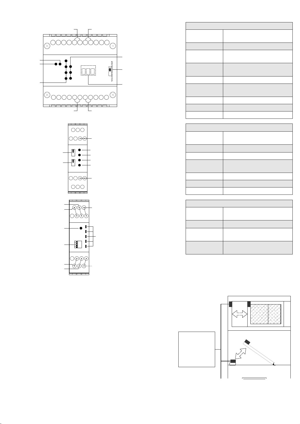
ISIS-4 - Control Unit
The ISIS-4 is a combined Safety Switch and E-Stop control
unit. Along with the ability to monitor up to four ISIS safety
switches it can also monitor the normally closed contacts of
emergency stop buttons or mechanical safety switches in
dual channel control circuits.
The ISIS-4 has 2 normally open safety contact outputs and 1
normally closed auxiliary output, an external re-set/proving
circuit and LED indication for ‘Power’, ‘Run’ and the status of
each activated gate switch.
ISIS-2 - Control Unit
The ISIS-2 control unit is a 24V ac/dc system that can
monitor up to 2 ISIS safety switches.
The ISIS-2 has 2 normally open safety contact outputs and 1
normally closed auxiliary output, an external re-set/proving
circuit and LED indication for ‘Power’, ‘Run’ and the status of
each activated gate switch.
ISIS-E - Extender Module
The ISIS-E Extender module is a 24V ac/dc unit that can be
added to either the ISIS-4 or ISIS-2 to monitor an additional
5 ISIS safety switches. Connection to the main control unit is
by a simple 2-wire bus connection. The status of each guard
switch is shown by the YELLOW LED’s. Additional ISIS-E
extender modules can be added to monitor larger systems.
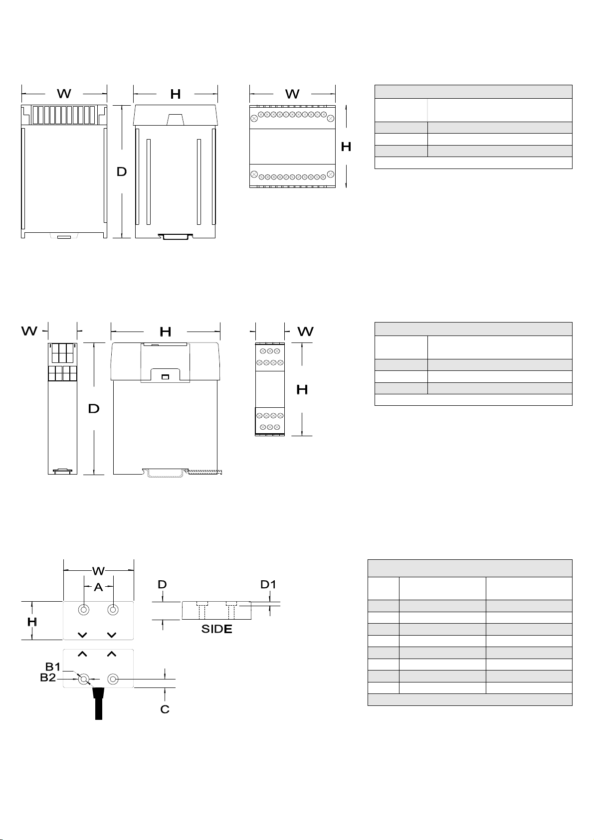
ISIS-03M / ISIS-SS-03M - Safety Switches
The ISIS safety switches are non-contact, tamper resistant
safety switches. Resin encapsulated into an ABS or
Stainless Steel case providing environmental protection to
IP67, the switches can withstand most conditions including:
water, dust and high pressure hose cleaning.
The 2-wire connection to each safety switch is
monitored by the control unit, detecting both open and
short circuit faults immediately and returning the control
unit to the off state even if the gate is not operated.
APPLICATIONS
Interlocked guards where door locking is not required.
Food and Beverage packing/filling systems; Diary,
Pharmaceutical, Paper Industry, Can Forming and Filling,
(Aluminum, Steel, Plastic), Semiconductor Manufacture/
Assembly. Concrete Block Manufacture.
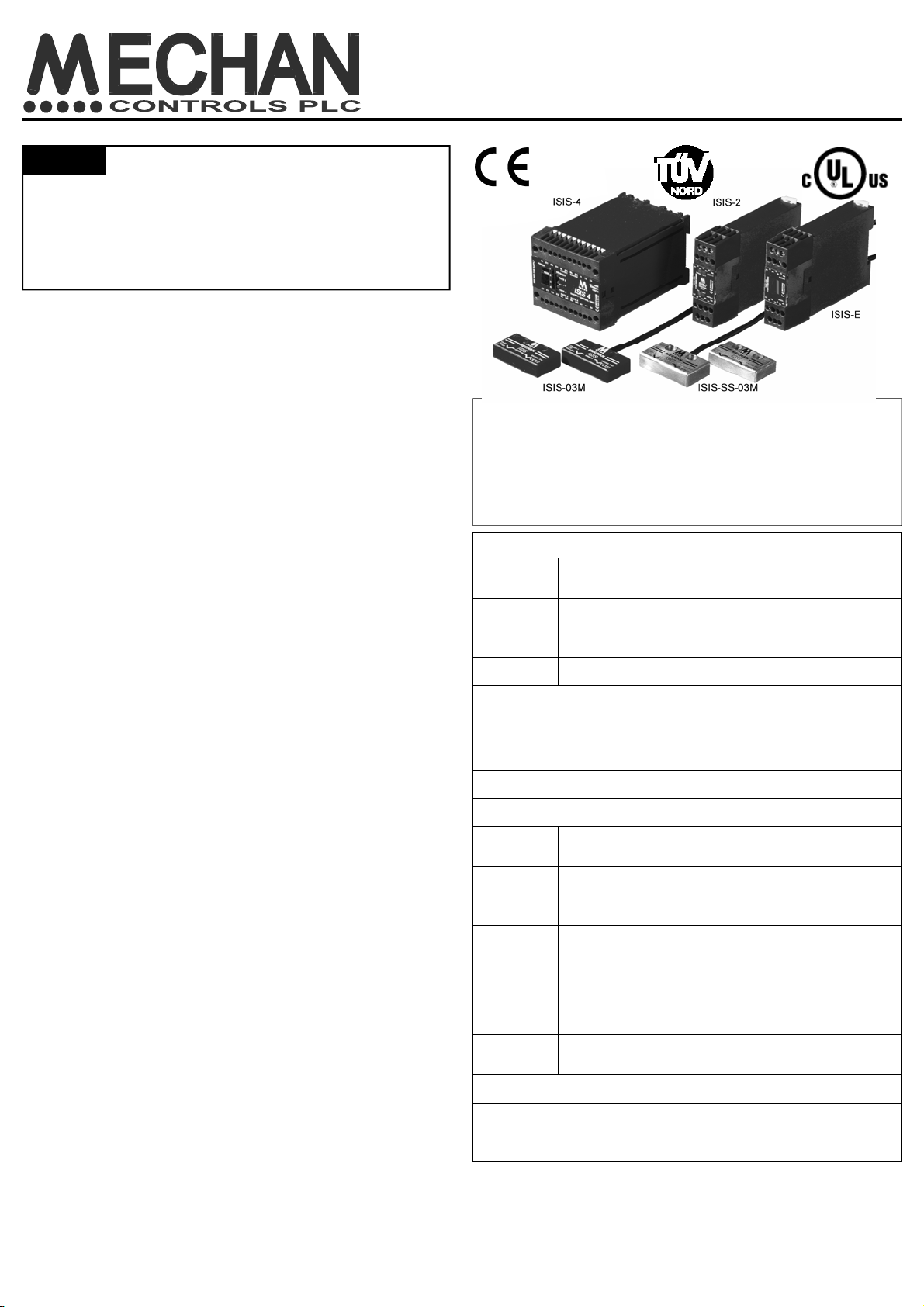
ISIS SAFETY SYSTEM
Installation guide
APPROVALS
CE Complies with the relevant sections of the CE
marking directive.
UL Tested by the Underwriters Laboratories, USA,
to comply with the relevant USA and Canadian
requirements. UL 508 Industrial Control
TUV CAT 3 SIL 3 PLe
EUROPEAN DIRECTIVES
Machinery Directive 2006/42/EC
Low Voltage Directive 2006/95/EC
Electromagnetic Compatibility Directive 2004/108/EC
EUROPEAN STANDARDS
EN ISO
13849-1 Safety of Machinery - Safety related parts of
control systems
EN ISO
62061 Safety of Machinery - Functional safety of safety
related electrical, and electronic and
programmable electronic control systems
EN 60204 Safety of Machinery - Electrical equipment of
machines.
EN 1088 Interlocking devices associated with guards.
EN
60947-5-3 Safety of Machinery - Specification for low
voltage switchgear and control gear.
CERTIFICATE OF CONFORMITY
A certificate of conformity can be supplied covering Mechan
non-contact safety switch equipment.
Call our technical help-line on +44 (0)1695 722264
EN 60947-
5-1 Low voltage switchgear and control gear.
UK Office
5 Caulside Drive, Antrim, BT41 2DU
United Kingdom
TEL: +44 (0) 28 9448 1800
www.pneutrol.com/industrialspares
European Office
Unit 6, Saint Anthony’s Business Park, Ballymount Road, D22 VW95
Ireland
TEL: +353 (0) 1 4373653
www.pneutrol.com/industrialspares
__________________________________________________________________________________________
Pneutrol International Limited

ISIS-4 TERMINAL INFORMATION
TERMINAL
NUMBER DESCRIPTION
A1 ; A2 Power Supply
S13 ; S14 E-Stop / Mechanical Safety
Input—Channel 1
S23 ; S24 E-Stop / Mechanical Safety
Input—Channel 2
X1 ; X2 External Proving / Reset
BL ; DR - Gate
inputs 1 to 4 Guard Switch Inputs
13 ; 14 N/O Safety Contact 1
23 ; 24 N/O Safety Contact 2
31 ; 32 N/C Auxiliary Contact
31
X1
13
BL
23
DR
A2
32
X2
14
BL DR
24
POWER - RED
GATE 1 - YELLOW
GATE 2 - YELLOW
RUN - GREEN
GUARD
SELECTOR
SWITCH
RESET
SELECTOR
SWITCH
A1
GATE 1 INPUT
GATE 2 INPUT
ISIS-2 TERMINAL INFORMATION
TERMINAL
NUMBER DESCRIPTION
A1 ; A2 Power Supply
X1 ; X2 External Proving / Reset
BL ; DR - Gate
inputs 1 & 2 Guard Switch Inputs
13 ; 14 N/O Safety Contact 1
23 ; 24 N/O Safety Contact 2
31 ; 32 N/C Auxiliary Contact
A1
DR
BL
DR
BL
DR
BL
A2
DR
BL
DR
BL BL
DR
POWER - RED
RESET
SELECTION
SWITCH
GATE STATUS
INDICATORS
(YELLOW)
GS5
GS4
GS3
GS2
BUS
GATE 2 INPUT
GATE 5 INPUT
GATE 1 INPUT
GATE 4 INPUT
GATE 3 INPUT
ISIS-E TERMINAL INFORMATION
TERMINAL
NUMBER DESCRIPTION
A1 ; A2 Power Supply
BL ; DR - Gate
inputs 1 to 5 Guard Switch Inputs
BL ; DR - BUS Bus connection to main
control unit
SYSTEM INSTALLATION
This installation guide is to help trained personnel to install the ISIS non-
contact safety switch system.
The ISIS system is suitable for most types of machine guarding
applications where guard locking is not required. The safety switches can
be fitted to sliding, hinged or removable machine guards.
Comprising of a Safety Control Unit ( ISIS-4 / ISIS-2 / ISIS-E) and one or
more Safety Switch and Actuators, systems can easily be assembled to
monitor 30+ machine guards whilst retaining the high control category
performance required in many applications. (CAT 3 according to EN954-1)
To assemble the system, mount the control unit in a suitably IP rated
control panel (Min IP54) and fix the safety switches to the gates as shown.
Connect the safety switches to the control unit. Using the appropriate
selection table set the required active gate inputs and reset options.
IMPORTANT :
PRODUCT IDENTIFICATION AND TERMINAL LAYOUT
HINGED DOORS
ISIS
Control
Unit
LIFT OFF DOORS
SLIDING DOORS
234
S13
A1
S23
X1 BL BL DRDR 31 13 23
S14
A2
S24
X2 BL BL DRDR 32 14 24
GATE 3 GATE 4
RUN - GREEN
POWER - RED
GUARD
STATUS
YELLOW
GUARD SELECT
GREEN
GUARD
SELECTOR
SWITCH
G
ATE 1 INPUT
G
ATE 2 INPUT
GATE 3 INPUT GATE 4 INPUT
GATE 1 GATE 2
RESET SELECTOR
SWITCH
Guard
Selector
Switch
UK Office
5 Caulside Drive, Antrim, BT41 2DU
United Kingdom
TEL: +44 (0) 28 9448 1800
www.pneutrol.com/industrialspares
European Office
Unit 6, Saint Anthony’s Business Park, Ballymount Road, D22 VW95
Ireland
TEL: +353 (0) 1 4373653
www.pneutrol.com/industrialspares
__________________________________________________________________________________________
Pneutrol International Limited

FITTING THE CONTROL UNIT
The ISIS control units are designed to fit standard 35mm symmetric DIN rail.
TO FIT : Hook the unit onto the DIN rail (1) and gently push into place (2).
The catch should hold the unit securely in place.
TO REMOVE: Place the tip of a small screwdriver into the white catch at the
bottom of the box (1) and gently lever out. This releases the retaining clip
and allows the unit to be tilted (2) and removed (3).
OFFON
1
2
12
3
GUARD SELECTOR & RESET SWITCHES
The central part of the ISIS control unit lid (1) is removable. Using a small screwdriver in the recess
(2) gently prise the lid upwards. This allows access to the Automatic/Manual monitored Reset
switch and the Guard Selector Switch.
Using the table next to the relevant control unit overleaf, set the ISIS control unit to the required
number of guard switch inputs and type of reset required.
IMPORTANT:
The number of inputs (safety switches) must match the gate selector setting.
Any incorrect setting will stop the system from operating correctly.
1
2
APPLICATION NOTES
FITTING THE SAFETY SWITCHES
The ISIS safety switch sensors have 2 pre-drilled fixing holes and are
supplied with M4 x 20mm TORX Tamper Proof fixing screws. (see page 7
for dimension details)
The gate switches can approach each other from any angle (A), but must
end up with the arrows on the printed face pointing towards each other.
Mount the fixed part of the safety switch to the machine frame and the
actuator on to the opening edge of the door (B).
For the best results, mount the sensors with a gap of approximately 1mm.
when the guard is closed. This gives a high level of lateral tolerance to
allow for ‘gate sag’ and freedom from nuisance tripping due to machine /
guard vibration.
WRONG!
B
A
Min. 50m
m
1) Always try to mount the safety switch on non-ferrous material.
Ferrous materials will reduce the switching distance.
2) Leave a minimum 50mm gap between actuators. (A)
3) Avoid mounting the safety switch on the hinged side of the
door, as this may allow the door to be opened too far before the
switch de-activates. (B)
CONNECTING SWITCHES TO THE CONTROL UNIT
The ISIS safety switches are supplied with 3 or 5 metres of cable encapsulated into the
fixed switch. This ensures a completely water-tight connection at the switch.
Cables can be extended using the same type of screened cable.
Run the cable back to the control unit through cable protection (if required) and
terminate into the appropriate control unit input channel.
Follow the colour coding of the wires to the labels on the control unit input terminals.
i.e. BLUE wire to BL and DRAIN wire to DR.
NOTE : High Temp Switches use Blue wire to BL & Brown wire to DR
Longer cable lengths are available to order.
MAX. 100
m
BL
DR
ISIS
CONTRO
L
UNIT
ISIS
SAFETY
SWITCH
A
B
IMPORTANT: Use the GATE inputs in sequence. Examples:
One Guard System—Use input 1 on the ISIS-2 ( Or input 1 on the ISIS-4 if E-Stop function required);
Three Guard System—Use inputs 1, 2 & 3 on the ISIS-4;
Seven Guard System—Use inputs 1,2 & 3 for Guard Switches on the ISIS-4 and Input 4 to connect to the ISIS-E Extender
module Bus connection. Then use inputs 1,2,3 & 4 on the ISIS-E
UK Office
5 Caulside Drive, Antrim, BT41 2DU
United Kingdom
TEL: +44 (0) 28 9448 1800
www.pneutrol.com/industrialspares
European Office
Unit 6, Saint Anthony’s Business Park, Ballymount Road, D22 VW95
Ireland
TEL: +353 (0) 1 4373653
www.pneutrol.com/industrialspares
__________________________________________________________________________________________
Pneutrol International Limited

ISIS-4 CONNECTIONS
POWER SUPPLY : 24Vac/dc ; 110Vac or 230Vac
POWER SUPPLY FUSING : Internal resetable fuse with 2
second delay after fault removal.
INDICATION : RED - Power On; GREEN - Run.
YELLOW - Guard Status indicators.
GREEN - Guard Selected status.
GUARD SELECTION : See ISIS-4 switch table.
RE-SET & MONITORING : The X1, X2 circuit is for reset
buttons and/or monitoring external contactors.
Set to Manual Reset (see table) a normally open
momentary push button should be placed across X1 & X2.
The push button must be pressed and released as it is
monitored for short circuit faults.
Set to Automatic Reset, link X1, X2 and the system will
reset when all active guards are closed.
To Monitor External Contactors (K1 & K2) place a
normally closed contact off each contactor in series with
X1 & X2 (with or without a reset button as required) If
either K1 or K2 welds during operation, the other contactor
will operate correctly and on the next demand on the
safety system the X1 X2 circuit will prevent a restart. Use
PGC relays for K1 & K2 if monitoring required.
CONTROL CONTACTS : Two sets of positively guided N/O safety contacts on terminals, 13,14; and 23,24 (rating 4 Amps).
One auxiliary N/C contact, (31-32). External fusing is recommended.
EMERGENCY STOP MONITORING : Dual channel emergency stop buttons and/or mechanical safety switches can be
monitored using the S13/S14 & S23/S24 circuits. If this feature is not used link terminals S13 to S14 and S23 to S24.
OPERATION : When power is applied to the control module, the RED ‘Power Led’ will illuminate. The GREEN ‘De-select’
indicators will show how many guard switch inputs are activated. NOTE: The number of inputs selected must match the
number of guard switches, more or less and the control unit will not operate. The YELLOW ‘Guard status’ indicators will be
illuminated if the guard is closed or be permanently on if the guard is de-selected.
If all the monitored machine guards are closed, the EMERGENCY STOP buttons (when used) are re-set and the RE-SET
button is pressed and released (Manual Re-set Option), the control relays will energize closing the normally open safety
contacts on terminals 13,14 / 23,24 and the normally closed auxiliary contact 31 & 32 will open. The GREEN Run LED will
illuminate. If set to automatic re-set ( I.e. link in X1 & X2) the control relays will energize when all active guards are closed and
the emergency stop button(s) are re-set. Faults on the safety switch cables, either open or short circuit will be detected
immediately causing the control relays to de-energize.
Single faults on the Emergency stop contacts will be detected upon the next demand and will prevent a restart.
ISIS-4 RESET AND MONITORING
SWITCH
Reset
Switch
Position Operation
Automatic Reset
Link required between
terminal X1 & X2. ISIS-4 will
reset when all active guards
are closed.
Manual / Monitored Reset
Requires a reset button in
the X1—X2 connection. The
system will reset when all
ISIS-4 GUARD SELECTION SWITCH & INDICATION
Guard
Indication
(Yellow)
De-select
Indicator
(Green)
Channel
Selector
Switch Operation
1 Gate Operation—Yellow LED No. 1 will
illuminate when gate switch 1 is closed.
All other Yellow gate indicators will remain
illuminated. No green LED’s illuminated.
2 Gate Operation—Yellow LED’s 1 & 2 will
illuminate when corresponding gate switch is
closed. All other Yellow gate indicators will remain
illuminated. Top green LED illuminated.
3 Gate Operation—Yellow LED’s 1,2 &3 will
illuminate when corresponding gate switch is
closed. All other Yellow gate indicators will remain
illuminated. Top two green LED’s illuminated
4 Gate Operation—Yellow LED’s 1,2,3 & 4 will
RUN
POWER
GATE 4GATE 3
4
3
2
1
GATE 4
GATE 3
GATE 2
DE-SELECT
A1
S13 S23
X1 BL DR BL DR 31 13
23
A2
S14 S24
X2 BL DR BL DR 32 14 24
GATE 2GATE 1
GS3GS4
GS1GS2
K1 K2
MECHANICAL
SAFETY
SWITCHES
or
EMERGENCY
STOP
K1
K2
MANUAL
RE-SET
L (+ve)
N (-ve)
K1
K2
F1
F2
UK Office
5 Caulside Drive, Antrim, BT41 2DU
United Kingdom
TEL: +44 (0) 28 9448 1800
www.pneutrol.com/industrialspares
European Office
Unit 6, Saint Anthony’s Business Park, Ballymount Road, D22 VW95
Ireland
TEL: +353 (0) 1 4373653
www.pneutrol.com/industrialspares
__________________________________________________________________________________________
Pneutrol International Limited

ISIS-2 CONNECTIONS
POWER SUPPLY :
24Vac/dc
POWER SUPPLY FUSING :
Internal resetable fuse with 2 second delay after fault removal.
INDICATION :
RED - Power On.
GREEN - Run.
YELLOW - Guard Status.
GUARD SELECTION :
See ISIS-2 Guard selection chart.
RE-SET & MONITORING :
The X1, X2 circuit is for reset buttons and/or monitoring external contactors.
Set to Manual Reset (see table) a normally open momentary push button should be
placed across X1 & X2. The push button must be pressed and released as it is
monitored for short circuit faults.
Set to Automatic Reset, link X1, X2 and the system will reset when all active guards
are closed.
To Monitor External Contactors (K1 & K2) place a normally closed contact off each
contactor in series with X1 & X2 (with or without a reset button as required) If either
K1 or K2 welds during operation, the other contactor will operate correctly and on the
next demand on the safety system the X1 X2 circuit will prevent a restart. Use PGC relays for K1 & K2 if monitoring required.
CONTROL CONTACTS :
Two sets of positively guided N/O safety contacts on terminals, 13,14; and 23,24 (rating 4 Amps). One auxiliary N/C contact,
(31-32). External fusing is recommended.
OPERATION :
When power is applied to the control module, the RED ‘Power Led’ will illuminate. The number of inputs selected must match
the number of guard switches, more or less and the control unit will not operate. The YELLOW ‘Guard status’ indicators will be
illuminated if the guard is closed or be permanently on if the guard is de-selected.
If all the monitored machine guards are closed and the RE-SET button is pressed and released (Manual Re-set Option), the
control relays will energize closing the normally open safety contacts on terminals 13,14 / 23,24 and the normally closed
auxiliary contact 31 & 32 will open. The GREEN Run LED will illuminate.
If set to automatic re-set ( I.e. link in X1 & X2) the control relays will energize when all active guards are closed and the
emergency stop button(s) are re-set. Faults on the safety switch cables, either open or short circuit will be detected
immediately causing the control relays to de-energize.
ISIS-2 RESET AND MONITORING
SWITCH
Reset
Switch
Position Operation
Automatic Reset
Link required between
terminal X1 & X2. ISIS-2 will
reset when all active guards
are closed.
Manual / Monitored Reset
Requires a reset button in
the X1—X2 connection. The
system will reset when all
ISIS-2 GUARD SELECTOR SWITCH
& INDICATION
Gate
Indication
Yellow
Gate
Selector
Switch Operation
1 Gate Operation—Yellow
LED No. 1 will illuminate
when gate switch 1 is
closed. Yellow LED No. 2
will remain illuminated.
2 Gate Operation—Yellow
LED’s 1 & 2 will illuminate
when corresponding gate
IMPORTANT
On all ISIS safety control
units use the guard inputs
in sequence.
Always set the control unit
guard selector switch to
match the number of safety
switches fitted
Any other setting may
cause improper operation.
GATE 2
A1 X1 BLDR31 13 23
A2 X2 BLDR32 14 24
GATE 1
GS2
GS1
K1 K2
K1
K2
24V
(+ve)
0V
(-ve)
K1
K2
F1
F2
POWER
IND 1
IND 2
RUN
MANUAL
RE-SET
UK Office
5 Caulside Drive, Antrim, BT41 2DU
United Kingdom
TEL: +44 (0) 28 9448 1800
www.pneutrol.com/industrialspares
European Office
Unit 6, Saint Anthony’s Business Park, Ballymount Road, D22 VW95
Ireland
TEL: +353 (0) 1 4373653
www.pneutrol.com/industrialspares
__________________________________________________________________________________________
Pneutrol International Limited

ISIS-E
CONNECTIONS
POWER SUPPLY :
24Vac/dc
POWER SUPPLY FUSING :
Internal resetable fuse with 2 second delay after fault
removal.
INDICATION :
RED - Power On.
YELLOW - guard status indicators.
GUARD SELECTION :
See ISIS-E Guard selection chart.
CONNECTION TO MAIN CONTROL UNIT:
The ISIS-E can be connected to any active guard switch
input on an ISIS-2 or ISIS-4.
Connect the 2-wire BUS ( BL DR ) terminals on the ISIS-E
module to any activated guard input on the main control
module. (Max distance 100 metres)
For larger systems further ISIS-E extender modules can
be connected to active guard switch inputs on an ISIS-E
extender module.
OPERATION :
When power is applied to the control module, the RED
‘Power Led’ will illuminate. The number of inputs selected must match the number of guard switches, more or less and the
control unit will not operate. The YELLOW ‘Guard status’ indicators will be illuminated if the guard is closed or be permanently
on if the guard is de-selected.
If all the monitored machine guards are closed and the RE-SET button is pressed and released on the main control unit, the
control relays will energize and the normally open safety contacts on terminals 13,14 / 23,24 (main control unit) will close. The
normally closed auxiliary contact 31 & 32 (main control unit) will open. If set to automatic re-set ( i.e. link in X1 & X2) the
control relays will energize when all active guards are closed and the emergency stop button(s) (if connected) are re-set.
Faults on the safety switch cables, either open or short circuit will be detected immediately causing the control relays to de-
energize.
A1 BLDR
GATE 1
GS1
24 V
+ve
0 V
-ve
BLDR BLDR
GATE 2 GATE 3
GS2 GS3
A2 BLDR
GATE 4
GS4
BLDR BLDR
GATE 5 BUS
GS5
IND 1
IND 2
IND 3
IND 4
IND 5
2-WIRE BUS CONNECTION
POWER
I
S
I
S
-E Extender Module
(24VDC) I
S
I
S
C
ontrol Unit
(24VDC)
BL DRA2
A1
ISIS-4 or ISIS-2
CONTROL UNIT
Connect the ISIS-E
Bus connection to
an active gate input.
ISIS-E GUARD SELECTOR SWITCH & INDICATION
Guard
Indication
(Yellow)
Channel
Selector
Switch Operation
1 Gate Operation—Yellow LED
No. 1 will illuminate when gate
switch 1 is closed. All others gate
indicators remain illuminated.
2 Gate Operation—Yellow LED’s
1&2 will illuminate when
corresponding gate switch is
closed. IND 3, 4 & 5 remain
illuminated.
3 Gate Operation—Yellow LED’s
1,2 &3 will illuminate
corresponding gate switch is
closed. IND 4 & 5 remain
illuminated.
4 Gate Operation—Yellow LED’s
1,2,3 & 4 will illuminate when
corresponding gate switch is
closed. IND 5 remains illuminated.
5 Gate Operation—Yellow LED’s
1,2,3,4 & 5 will illuminate when
corresponding gate switch is
12 GATE SYSTEM
with E-STOP Control
ISIS-4
Set to 4 gate operation
1st ISIS-E
Set to 5 gate operation
2nd ISIS-E
Set to 5 gate operation
10 GATE SYSTEM
ISIS-2
Set to 2 gate operation
1st ISIS-E
Set to 5 gate operation
6 GATE SYSTEM with
E-STOP Control
ISIS-4
Set to 4 gate operation
ISIS-E
Set to 3 gate operation
SYSTEM EXAMPLES WITH EXTENDER MODULES
UK Office
5 Caulside Drive, Antrim, BT41 2DU
United Kingdom
TEL: +44 (0) 28 9448 1800
www.pneutrol.com/industrialspares
European Office
Unit 6, Saint Anthony’s Business Park, Ballymount Road, D22 VW95
Ireland
TEL: +353 (0) 1 4373653
www.pneutrol.com/industrialspares
__________________________________________________________________________________________
Pneutrol International Limited

Dimensions ISIS-4
(mm / inches)
W 75 / 2.95
H 74 / 2.91
D 119 / 4.68
Information only
Dimensions
ISIS-2 & ISIS-E
(mm / inches)
W 22.5 / 0.88
H 84 / 3.3
D 119 / 4.68
Information only
Dimensions
ISIS-03M
(mm / inches) ISIS-SS-03M
(mm / inches)
H 28 / 1.1 29 / 1.14
W 52 / 2.04 53 / 2.08
D 14 / 0.55 13.5 / 0.53
D1 3 / 0.11 3 / 0.11
A 22 / 0.86 22 / 0.86
B1 4.2 / 0.16 dia. 4.2 / 0.16 dia.
B2 8.1 / 0.32 dia. 8.1 / 0.32 dia
C 6.4 / 0.25 6.4 / 0.25
Information only
DIMENSIONS
ISIS-4 (all voltages)
ISIS-2 & ISIS-E
ISIS SAFETY SWITCHES ABS / STAINLESS STEEL
UK Office
5 Caulside Drive, Antrim, BT41 2DU
United Kingdom
TEL: +44 (0) 28 9448 1800
www.pneutrol.com/industrialspares
European Office
Unit 6, Saint Anthony’s Business Park, Ballymount Road, D22 VW95
Ireland
TEL: +353 (0) 1 4373653
www.pneutrol.com/industrialspares
__________________________________________________________________________________________
Pneutrol International Limited

TECHNICAL INFORMATION
SPECIFICATIONS ISIS CONTROL UNITS ISIS SAFETY SWITCHES
ISIS-4 ISIS-2 ISIS-E ISIS-03M / 05M ISIS-SS-03M
Supply nominal voltage 24Vac/dc
110 or 230Vac 24Vac/dc 24Vac/dc - -
Nominal power consumption 6VA 3VA 3VA - -
Safety contacts 2 x N/O - - -
Auxiliary contact 1 x N/C - - -
Output contact rating (max) 4A/230Vac; 2A/24Vdc(Res.)@Cos=1 - - -
Output contact rating (min) 10V/10mA - - -
Output contact fuse rating AC=5A; DC=2.5A; Quick blow - - -
Drop out time Deactivation by sensor 13ms - -
Nominal voltage across BL/DR sensor ON: 4V; OFF 0 to 10Vdc
Internal fuse 500mA Resettable - -
Internal fuse recovery time >2 Seconds - -
Internal switches Active gate selector; Manual or
Monitored reset selection Active gate
selector - -
Max conductor size 1 x 2.5mm stranded with sleeves, 1 x 4mm solid - -
Installation group (Control unit) C in accordance with VDE0110 - -
Contamination level
Vibration resistance Amplitude 2mm, frequency 10 to 55 Hz -
Enclosure protection Housing IP40, Terminals IP20 IP67
Switching distance - - - 5-7mm ON; 8-12mm OFF
Minimum gap 1mm
Cable length 3 or 5 metres (Max 100 metres)
Operating temperature -10C to +55C (85% Humidity max) -10C to +55C
-10C to + 125C (SS High Temp.)
Storage temperature -20C to +60C -20C to +60C
Housing material Polycarbonate Red ABS Red 316 Stainless
Steel
Mounting / Fixing 35mm Symmetric DIN Rail 22mm Centres;
M4 security screws supplied
Tightening torque 1.0NM
Weight (AC/DC) (3m/5m) 575g max. 183g 135g 207g max 265g
Dimensions See page 7
III
Safety Related Data
PL In accordance with EN ISO 13949-1 PL e, CAT 3
SIL In accordance with EN ISO 62061 SIL 3
PFHd in accordance with EN ISO 62061 3.37 x 10⁻⁸
PFH 5.63 x 10⁻⁸
B10d 2,000,000
MTTFd High > 100 Years ( Based on usage rate of 360 days/year, 24 hours/day, 10 operations/hour
TM (Mission Time ) 20 Years
DC 99%
SFF 99.4%
Document Number : 370-400v13
UK Office
5 Caulside Drive, Antrim, BT41 2DU
United Kingdom
TEL: +44 (0) 28 9448 1800
www.pneutrol.com/industrialspares
European Office
Unit 6, Saint Anthony’s Business Park, Ballymount Road, D22 VW95
Ireland
TEL: +353 (0) 1 4373653
www.pneutrol.com/industrialspares
__________________________________________________________________________________________
Pneutrol International Limited
This manual suits for next models
6
Table of contents
Other Mechan Safety Equipment manuals
Popular Safety Equipment manuals by other brands

Firex
Firex EXITE-LTX EXEXCM Installation & Maintenance Instruction Manual

Eller
Eller P-35C instructions

Hurst Jaws Of Life
Hurst Jaws Of Life eDRAULIC SC 250 E2 instruction manual

Millenium
Millenium Metal Plus LLC instruction manual

Contrinex
Contrinex YBB Series instruction manual

Guardian
Guardian 42110 instruction manual