Spacing Charts and Information
6” 6-1/2 - 7" 7-1/2 - 8" 8-1/2” 9”
15.2cm 17.8cm 20.3cm 21.6cm 22.8cm
SPACING CHART FOR DIRECT DRIVE UNIT W/ 12 POCKET CHAIN
Number of Teeth on Sprocket on Unit
Double any of the above spacings by using every other pocket (6 pocket).
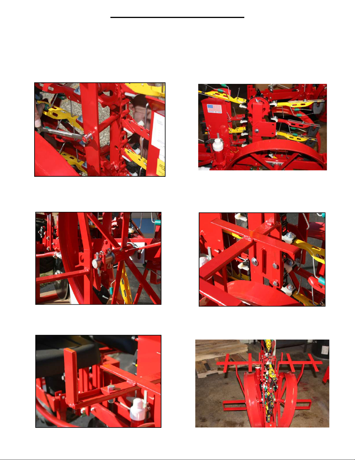
Make sure HITCH and UNIT are level or parallel to the ground when planting.
Sprocket on OUT-
SIDE of Jackshaft
Sprocket on
INSIDE of
Jackshaft
7 11
7 7
8 7
9 7
10 7
11 7
9” 10-1/2” 13” 15” 16”
22.8cm 26.7cm 33cm 38.1cm 40.6cm
15” 18”
38.1cm 45.7cm
10-1/2” 12-1/2” 14” 15” 16”
26.7cm 31.7cm 35.5cm 38.1cm 40.6cm
12” 13-1/2” 15” 17” 18-1/2”
30.5cm 34.3cm 38.1cm 43.2cm 47cm
13” 14” 15-1/2” 17-1/2” 20-1/2”
33cm 35.5cm 39.4cm 44.5cm 52cm
7 8 9 10 11
Use for Model 1000
7 8 9 10 11
Sprocket on
OUTSIDE
of Jackshaft
Sprocket on
INSIDE
of Jackshaft
Number of
Pockets
on the Disc
Number of Teeth on Sprocket by Disc
7 7
8 7
9 7
10 7
11 7
24
16
12
24
16
12
24
16
12
24
16
12
24
16
12
2” 2-1/4” 2-1/2” 2-3/4”
3” 3-1/4” 3-1/2” 4” 4-1/2”
4-3/4” 5-1/4” 5-3/4” 6-1/4”
3-1/2” 3-3/4” 4-1/4” 4-1/2” 5-1/4”
2-1/2” 3” 3-1/4” 3-1/2”
6” 6-1/4” 6-3/4” 7”
2-1/2” 2-3/4” 3-1/4” 3-1/2” 4”
3-3/4” 4-1/4” 4-1/2” 5” 5-1/2”
4-1/2” 6-1/4” 6-1/2” 7-1/4” 8”
2-1/2” 3” 3-1/2” 3-3/4” 4-1/2”
3-3/4” 4-1/2” 5-1/4”
5-1/4” 6” 7” 7-1/2” 8-1/2”
2-1/2” 3” 3-1/2” 4-1/4” 4-3/4”
4” 5” 6”
5-1/2” 6-1/2” 7-1/2” 9” 10”
Use for Model 1000 with disc mounted pockets
DISC SPACING CHART FOR MODELS W/ DIRECT DRIVE