MECHANICAL TRANSPLANTER 5500WD User manual

MODEL 5500WD
Assembly and Operators Manual
MECHANICAL TRANSPLANTER COMPANY, LLC
1150 CENTRAL AVENUE * HOLLAND, MI 49423-5230
Phone: 616-396-8738 * Fax: 616-396-3619
website: www.mechanicaltransplanter.com
e-mail: [email protected]

*

TABLE OF CONTENTS
1. Assembly
2. Carrousel Tray Holder
3. Operation and Timing
4. Service
5. Gauge Wheel Drive Spacing Chart
6. Troubleshooting
7. Parts Packing List

5500WD Drive Wheel Assembly Instructions
3. Bolt front drive wheel to frame using four
1/2 x 1-1/4” bolts and four 1/2” washers
and four 1/2” nuts. Washers go on outside
of frame as shown.
4. Slide #43 bushing onto 1/2 x 2” bolt. Place two
3/4” machinery bushings over the #43 bushing.
Insert bolt into front of the chain tightener
bracket. Place the second #43 bushing on
opposite side of chain tightener bracket. Insert
complete assembly into hole on frame as
shown in Photo #5 and secure with 1/2” nut.
1. Take the green seat brace and red chain guard
support bracket and loosely bolt together using
one 1/2 x 1-1/2” carriage bolt and 1/2” nut.
2.Slide the red bracket on inside of frame and
the green seat brace on outside of the front
frame plate. Secure with second 1/2 x 1-1/2”
carriage bolt and 1/2” nut through bottom hole.
Adjust seat brace up or down for proper height.
5. After chain tightener is in place lay chain over
sprockets and around chain tightener rollers
as shown. 1

7. Re-install the back round guard. Then slide
front guard over pin fastened to seat brace
in step 2 and secure with #17 clip pin.
6. Take #373 spring and hook it onto chain
tightener. Extend spring and fasten in
hole on fl at spring holder as shown.
2

4. Slide the end link of the chain onto the bolt.
5. Secure the chain with a 3/8” washer and then a 7/16” hex nut. Make sure the nut is very tight.
Inform MTC of the size of toolbar and the correct clamps will be shipped with unit. Dealer or customer
should notify us as to which type of toolbar clamps are needed if not ordering the toolbar from us.
2. Attach the clamp to the bolt in the top hole of the bottom set
of large holes. Secure with a 1/2” hex nut.
3. If you have a Model 5500WDB-3 or 5500WD-2 follow
directions below for one clamp side only. To mount safety
bar on other clamp side, see page 5. In the top set of holes,
place a 7/16 x 1-1/4” bolt through the top hole.
Instructions for Direct Drive Clamps
The following instructions are for mounting the direct drive clamps to your Model 5500WD unit.
although the pictures show the 2-1/2” clamps. Use these instructions for any clamp style. They
all mount the same way.
1. Insert a metal bushing from the inside of the frame. Put one of
the 1/2 x 1-1/2” bolts through the bushing also from the inside.
3

6. Use the same instructions for the other side of the Direct Drive Wheel.
Note: The clamps may be reversed or fastened on the inside of the frame for narrow row
spacings. If other clamps are in the way, two lefts or two rights may be used. The
lower holes on the clamps are for higher toolbars on older models or on trailers
where 3-point hitch will not go low enough. Correct height of toolbar is 14” to center.
The Model 5500WD unit can now be mounted to your 3-point hitch or toolbar.
Following is a list of fastneers that you must use for various toolbars.
Toolbar Hardware List
2-1/2” or 2-1/4” Diamond Toolbar - 7/8” V-bend U-Bolts (2)
3” x 3” Flat Toolbar - 3/4” x 5” Hex Bolts (4)
4” x 4” Flat Toolbar - 3/4” x 6” Hex Bolts (4)
4” x 7” Toolbar - 3/4” x 9-1/2” Hex Bolts (4)
5” x 7” Toolbar - 3/4” x 7” Hex Bolts (4)
7” x 7” Toolbar - 3/4” x 9-1/2” (4)
Shown with clamps reversed
4” x 7” Toolbar Clamp. Use 2-3/4” x 9-1/2” Hex
Bolts, 2-3/4” Hex Nuts and 2-3/4” Washers.
Note: Bent bracket on front of clamp
must be on top.
4

Model 5500WD Barrel Mounting and 3-Point Hitch Instructions
3-Point Hitch & Barrel Mounting
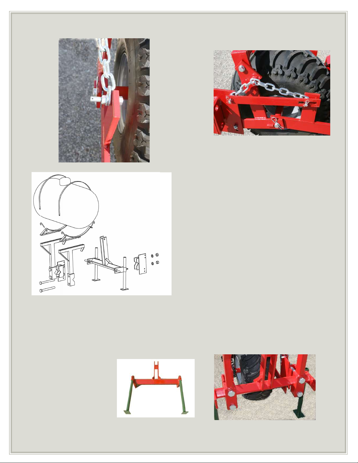
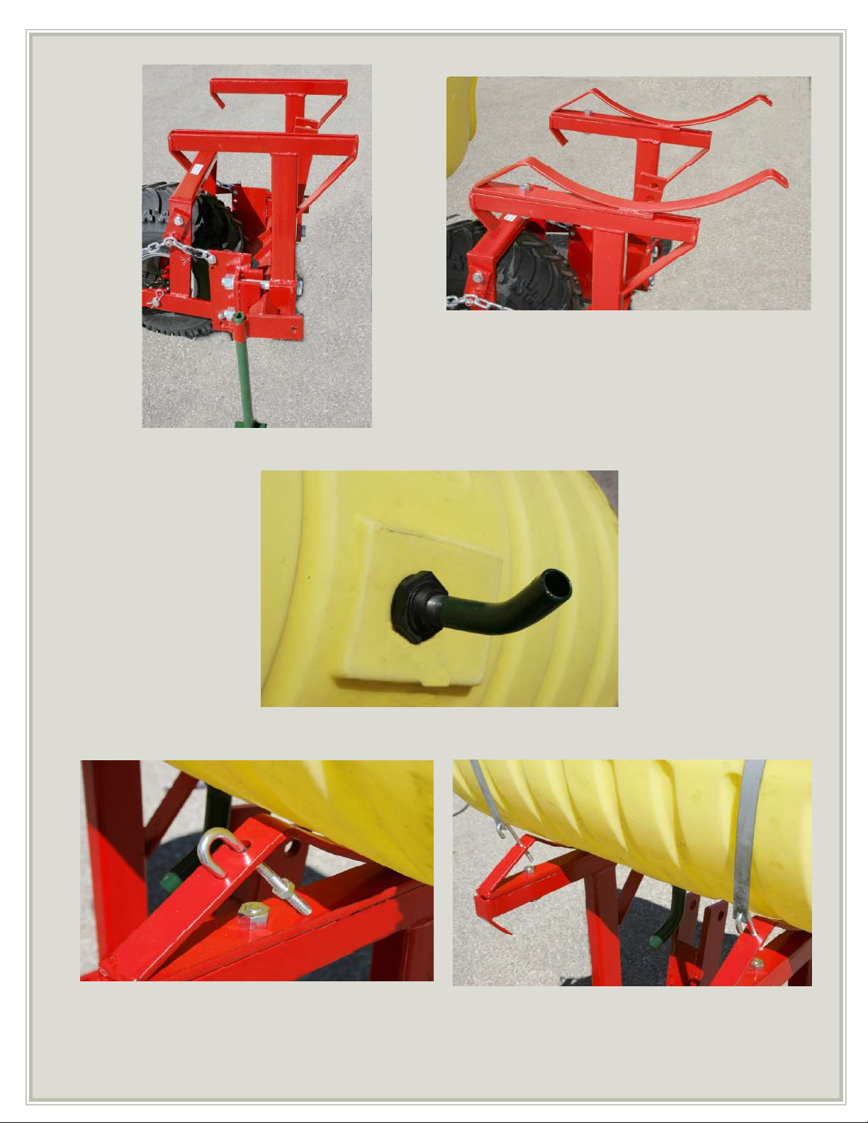
1. On the 3-Point hitch, connect the Category I hitch pins through the holes on the outside of the hitch.
Put the pins in through the outside and secure with the lock washer and hex nut included with the pin.
2. Slide the green pipe stands up through the pipes on the hitch, then tighten by turning the set screw.
Note: The following steps
will be easier with two
people
3. Center the 3-Point hitch toolbar with the clamps on your transplanter. Next, line up one of the barrel mounting
brackets with the direct drive clamps. Secure using two 1 x 8-1/2” bolts and hex nuts. Do the same with the
other barrel mounting bracket.
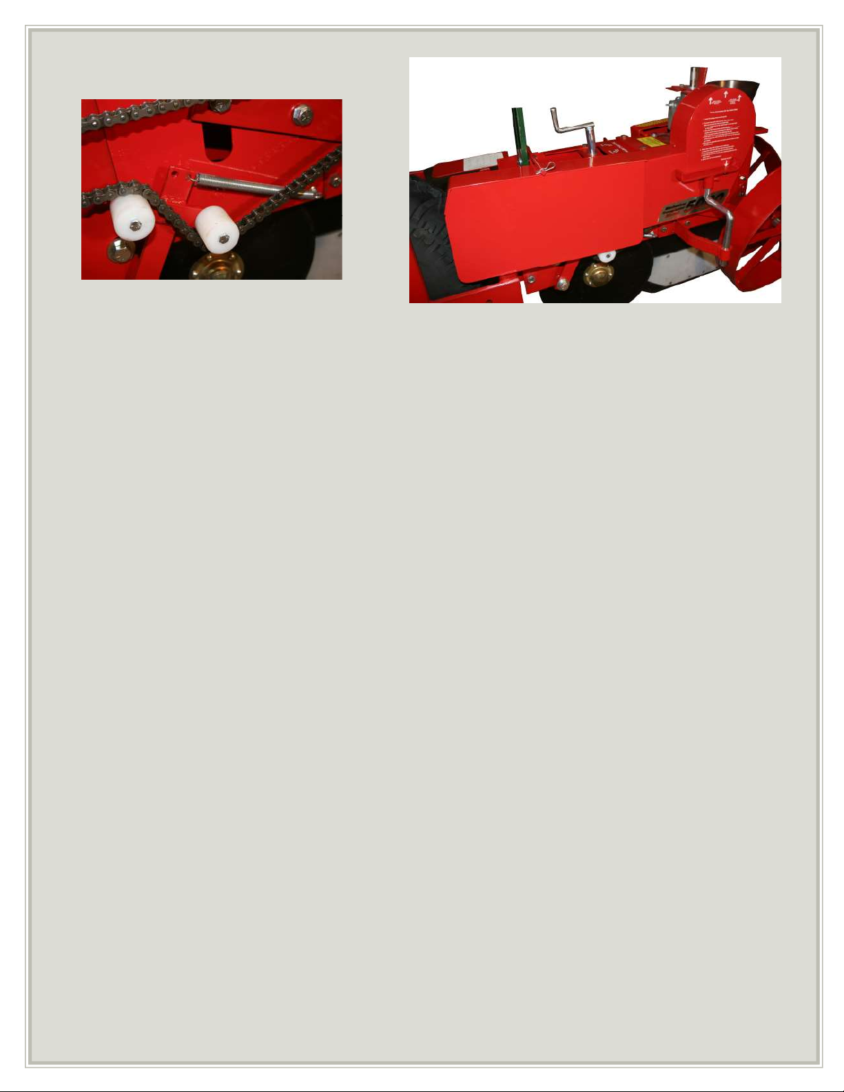
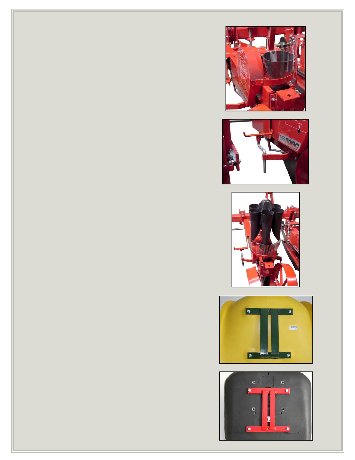
To mount this safety bar, you must remove the 7/16
x 1-1/4” bolt from on side of the direct drive wheel.
1. Locate the special 2-1/2” stud in your bag
of bolts and nuts.
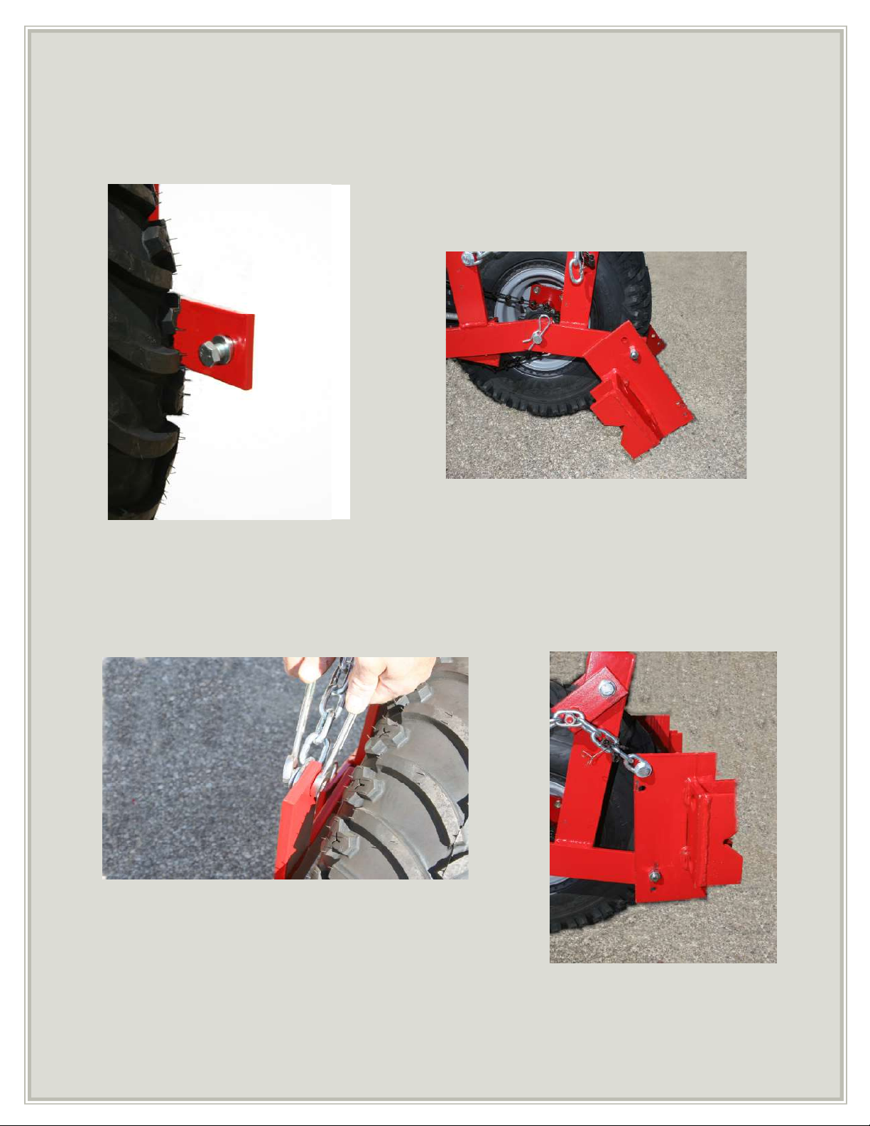
2. Turn a 7/16” hex nut all the way onto the stud.
3. Put the 7/16” washer on the stud next to the nut.
4. Place the lift chain up against the washer.
5. Slide the stud through the hole on the Direct
Drive frame and secure with a 7/16” hex nut.
6. Assemble another stud the same way and fasten
it to the top hole of the front Direct Drive clamp.
7. Attach the red seat safety bar to the stud on your
drive wheel. The end with the hole must go on the
clamp. The slotted end must go on the frame.
After the safety bar is attached, place small clip
pins through the small holes.
5

Side view of B-3 mountings
4. Bolt barrel hoops onto B-3 supports using 1/2 x 3” hex
bolt with 1/2” lock nut. Note below: the hoops can be
mounted in a forward or back position, depending
on clearance that you need for the tractor fenders etc.
5. Screw in the nipple into the bottom of the tank.
6. Insert J-bolts into the four holes on the barrel
hoops. It works best to thread 5/16” nut onto
J-bolt before hooking up barrel hoops.
7. The 55 gallon poly tank can now be mountied
on top of the barrel mountings. Use the four J-bolts
and the galvanized straps to secure the barrel to
the mountings.
6

WINDSHIELD
Install the windshield on the back
of the transplanter. Use one 5/16 x 1/2”
bolt with the small washer into the
threaded hole by the large drop tube.
Adjust the footrests to desired position
with the two square head set screws.
Place the six tube carrousel feeder
onto the vertical shaft of the gearbox.
Align the key in the tubing with the
keyway in the vertical shaft. Tighten
using the square head set screw.
MOUNTING CUSHION SEAT
Put the 1/2 x 1-1/2” carriage bolt through the
bottom of the green seat bracket before
mounting the seat bracket to the seat. After
placing the carriage bolt through the seat
bracket, place the seat bracket on the cushion
seat. Secure with four 5/16 x 1/2” hex head
bolts. Place the seat on the L-shaped seat
bracket and secure with a 1/2” washer and
hex nut.
Turn fi berglass seat over and remove any
plastic covering the threaded studs. Take your
green seat bracket and mount it to the bottom
of the seat with the side with the bend toward
the front of the seat. Secure with four 1/4” hex
nuts. Put the 1/2 x 1-1/2 carriage bolt through
the brace and then through the L-shaped seat
bracket. Secure with a 1/2” washer and hex nut.
MOUNTING FIBERGLASS SEAT
FOOTREST
6-CUP CARROUSEL
7

MODEL 5500WD OPERATION
A. Timing Instructions
1. The diagram below is on the side of your transplanter. The arrows
signify the location of a tube with the lower keyway straight up.
2. Follow the instructions below carefully. This must be done with each transplanter.
Keyway in shaft
Slower setting
(Tobacco)
Timing Instructions for the Model 5500WD
1. Locate the timing arrows on this guard.
2. To insure that each unit is in time, follow these steps
(this must be done for each unit separately).
a. Observe the keyway on the shaft located in the open hole
on this guard.
b. Turn the drive wheel slowly until the keyway is at the 12 o’clock
position and the arrow is pointing at it. Keyway must remain
at the 12 o’clock position while adjusting the cups.
c. If the center arrow is pointing at the center of the bottom of any
of the 6 cups, your unit is in time for approximately 80-100 plants
per minute.
e. The cups are adjustable from the center arrow for slower or faster
planting speeds.
3. Follow these steps if the timing must be adjusted:
a. Loosen the 1/2” bolt at the top of the six cup feeder head.
b. Remember to keep the keyway at the 12 o’clock position.
c. Rotate the six cup feeder head to your desired position from the
center arrow.
d. Tighten the 1/2” bolt and proceed.
Faster setting
(California
vegetables)
8

Correct Correct
2. It is very important when starting to transplant, that the lift chains on the side of the
Direct Drive Wheel are loose. Note above correct picture.
3. When lowering the transplanting unit into the ground, be sure that hte frame members
on the Direct Drive Wheel run parallel as is shown in the above set of pictures. This is
adjusted by the height of the hitch or toolbar (a pair of gauge wheels will eliminate ad
justment of toolbar height).
4. Running the frame parallel will keep the lift chains loose allowing for proper fl oatation
in the Direct Drive Wheel.
5. Running the frame members parallel and level will allow the packing wheels to run in
the proper packing position.
6. Running the toolbar too low will tighten the back chains and cause the packing wheels
to run too light and not pack the soil properly.
7. Running the toolbar too high will tighten the front lift chains and cause the drive wheel
to not run on the ground especially through low spots.
C. Direct Drive Float Wheel Operaton
1. Only use 4 to 5 pounds of air pressure into the Direct Drive Wheel during operation.
9
B. Sizing cell to shoe
1. Take a cell and place into the rear of the shoe.
2. Using a 15/16” wrench, adjust the bolt on the outside of the shoe to widen or narrow the shoe.
Cell must fi t snugly, stopping near bottom of shoe.
Incorrect
- Narrow the shoe
with adjustment
bolt.
Incorrect
- Widen the shoe
with adjustment
bolt.

Set the ball valve on side of unit for desired amount of water to be released with each plant.
2. If a smaller stroke is desired, remove the inspection plate in front of the gearbox.
Raise the #5199 channel on the pump rod to decrease the stroke.
Do not over or under stroke valve or it will lock up the unit.
3. Water placement can be adjusted to trip earlier or later than its current set position. To adjust,
loosen the thumb screw on the dial located on the side of the transplanter. Start from the center
position and move the dial in small increments. Turning the dial clockwise will cause the water
to drop earlier and turning the dial counter-clockwise will cause it to drop later.
4. Drain the water out of the valve at the end of the season or the valve could freeze and be damaged.
E. Depth Control and Packing
1. If the depth of the cell planted is incorrect, turn the crank under the seat to set the shoe deeper or shallower.
2. The packing wheels can be adjusted closer together or further apart with the set screws found on
the packing wheel hubs.
Added pressure can be given to the back of the transplanter by lengthening the 3rd arm
of the 3-point hitch or shortening the bottom link arms on the pull-type trailer.
F. Water Valve Adjustment
1. The water valve is set at the factory for maximum stroke.
10
D. Kicker Adjustment
1) Factory preset is at 1/4” out of shoe.
2) If kicker is not coming out of the shoot at 1/4”, then adjust eccentric bolt with wrench.

TROUBLE SHOOTING
Reminder: Cell-type setters, such as the Model 5500WD, require a fi rm, rootbound,
and moist cell for consistent planting. A poor quality cell directly affects
the performance of the transplanter.
PROBLEM CAUSE SOLUTION
Plants fall on kicker Machine is out of time
Poor cell quality
and/or dry cells
Review decal on side of transplanter
or see page 10 in the manual
Water cells lightly to help them drop
faster
See the diagram on page 11 of this
manual
Make sure the cells are fully
intact when removing from
the tray
Plants are buried or
lying top of the soil
The furrow opening shoe
is not adjusted properly
Poor cell quality
Clean shoe with putty knife.
Rototill soil.
Furrow is not fi lling
in properly
Furrow sides of opening
shoe have built up
Use as last resort
Close ball valve until proper
water fl ow is achieved
Plants are being
fl ooded out of shoe
Ball valve on side of trans-
planter opened too much
11
Attention: Care should be taken while servicing the unit because of the bolt together construction of the
main frame. NEVER remove the unit top plate, backplate, or shoe at the same time. Frame
alignment could be jeopardized if this is done!
A. Resetting the transplanter to factory timing. See page 8.
B. Replacing the Shoe
1. Loosen and remove the two 3/8” bolts going into the bottom of the framework at the back of the shoe.
2. Remove the 3/8” bolt from the front of the shoe.
C. Kicker spring replacement
1. Remove any plant racks or carrousel tray holders
2. Loosen the four bolts holding the back plate on
3. Remove the back plate for easy access inside the transplanter
Service

4 - 1/2 x 1-1/4 Hex Bolt
3 - 1/2 x 1-1/2 Carriage Bolt
1- 1/2 x 2 Hex Bolt
1 - #15 Clip Pin
8 - 1/2 Nut
5 - 1/2 Washer
1 - #40 x 110 Chain
2 - #43 Bushing
1 - Chain Tightener
2 - 3/4 Machinery Bushing
1 - #373 Spring
1 - 5/16 X 1/2” bolt with washer
In Box
1 - #726 Seat Brace
1 - Chain Guard
1 - Seat Brace Plate
1 - Parts Bag
Parts Bag For 5500WD
Spacing Charts
12
MODEL 5500WD CLOSE SPACING CHART MODEL 5500WD WIDE SPACING CHART

Safety Precautions
1. Make sure tractor is stopped and in neutral with the transplanter lowered to the
ground before getting on and off the unit.
2. No operator is allowed to be on the unit as it is raised and lowered.
3. No operator is allowed on the transplanter as it is transported to or from the fi eld.
4. All operators must be seated before movement begins and remain seated until the
transplanter is completely stopped.
5. Never leave the transplanter in the raised position.
6. Keep all shields and guards in place when operating the transplanter.
7. Never attempt repairs or maintenance while the transplanter is in motion.
8. Never put the tractor in reverse while the transplanter is on the ground.
9. Follow all safety instructions supplied by the tractor manufacturer to which the
transplanter is mounted.
MACHINE IMPROVEMENTS
MECHANICAL TRANSPLANTER CO. IS ALWAYS STRIVING TO MAKE IMPROVEMENTS ON THEIR LINE
OF EQUIPMENT. MECHANICAL TRANSPLANTER CO. RESERVES THE RIGHT TO MAKE IMPROVEMENTS
AND CHANGES AT ANY TIME WITHOUT INCURRING OBLIGATIONS TO MAKE SUCH CHANGES OR
ADDITIONS TO EQUIPMENT PREVIOUSLY SOLD.
Limited Warranty
Mechanical Transplanter Company * 1150 Central Avenue * Holland, MI 49423
Phone: 616-396-8738 or Fax: 616-396-3619
website: www.mechanicaltransplanter.com * e-mail: [email protected]
Mechanical Transplanter Company warrants each item of new equipment manufactured by Mechanical to be free
from defects in material and workmanship under normal use and service.
The obligation of Mechanical Transplanter Company under this LIMITED WARRANTY is limited to repairing or
replacing as Mechanical may elect, and any parts that prove, in Mechanical’s judgment, to be defective in material
and workmanship within the fi rst season’s use or 45 consecutive days after initially placing equipment in operation,
whichever occurs fi rst. Any outside work or alterations without Mechanical’s written approval will render the
LIMITED WARRANTY void.
Mechanical’s obligation specifi cally excludes any liability for consequential damages, such as loss of profi ts,
delays, expenses, damage to goods or property used in connection with or processed in or by the product sold,
or damage to the product sold from whatsoever cause, whether or not such loss is due to negligence of selling
dealer of Mechanical Tranplanter Company.
This limited warranty shall not apply to any item or machine which shall have been operated in a manner not
recommended by the Company nor which shall have been repaired, altered, misused, damaged in an accident,
neglected, tampered with or used in any way which in the Company’s opinion adversely aff ects its performance
and results.
No person is authorized to give any other warranties or to assume any other liability on behalf of Mechanical
Transplanter Company, unless made in writing by Mechanical.
This limited warranty covers repair or replacement of Mechanical Transplanter Co. equipment only and does
not cover crop loss, downtime, labor, damage to other equipment, etc.
This limited warrantly does not apply to exterior fi nishes, tires, chain links, bearings, or any other items sold
by Mechanical Transplanter Co., but warranted by the original manufacturer except to the extent of their
individual manufacturer’s warranty.
THIS LIMITED WARRANT IS IN LIEU OF ALL OTHER WARRANTIES, EXPRESSED OR IMPLIED.
WARRANTIES OF MERCHANT ABILITY AND FITNESS FOR PARTICULAR PURPOSE ARE EXCLUDED,
AS ARE ALL OTHER REPRESENTATIONS TO THE USER-PURCHASER, AND ALL OTHER OBLIGATIONS
OR LIABILITIES, INCLUDING LIABILITY FOR INCIDENTAL AND CONSEQUENTIAL DAMAGES, ON
THE PART OF MECHANICAL OR THE SELLER.
Table of contents
Other MECHANICAL TRANSPLANTER Farm Equipment manuals