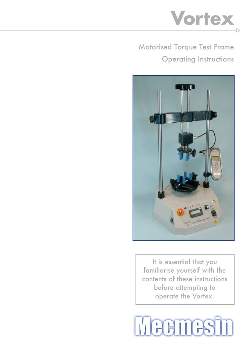
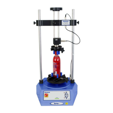
Mecmesin MultiTest 1-dV User manual

MultiTest-dV Tension and
Compression Test Stand
Operating Manual
431
-
459
-
04
February 2019

2 Mecmesin MultiTest-dV Operating Manual
The Scope of This Document
This document refers to Mecmesin MultiTest-dV test stands operating with firmware
version 3.0.10. It is essential that you familiarise yourself with the contents of this
manual and the separate ‘Guide to Safe Use of Mains Powered Test Systems’ before
attempting to operate your MultiTest-dV Test System.
You may also need to refer to these documents:
431-957 Long Travel Extensometer Installation Guide
431-955 VectorPro™ for Mecmesin Test Stands and Instruments
431-213 Advanced Force Gauge (AFG Mk4) Operating Manual
431-398 Guide to Safe Use of Mains Powered Test Systems
Important
This user manual covers the operation of MultiTest-dV force test stands in conjunction
with the use of Mecmesin digital Advanced Force Gauges, ELS devices and
extensometers. Operation of gauges and extensometers is covered in separate manuals
for these products.
For operating in conjunction with Vector Pro™, see the manual 431-955, VectorPro™ for
Mecmesin Test Stands and Instruments.
2018 © Mecmesin Ltd, supplied with Mecmesin test systems and not for redistribution
Part no. 431-459-04

MultiTest-dV Operating Manual Mecmesin 3
Contents
1. Items Supplied with the Test Stand 5
Accessories 5
2. MultiTest-dV System Diagram 6
3. MultiTest-dV – Dual Functionality 7
3.1. Identifying a Mark 2 MultiTest-dV 7
3.2. Functionality Differences 8
3.3. Switching dV Modes 9
3.4. License Keys 10
4. Initial Setup 11
4.1. Unpacking the Stand 11
4.2. Lifting the Test Stand 11
4.3. Environment Conditions 11
4.4. Mains Power Supply 12
4.5. Fuse Specification 12
4.6. Fitting the Feet to the Stand 13
4.7. Bolting the Test Stand to the Work Surface 14
4.8. Fitting and Connecting an AFG 15
Connecting an AFG to the MultiTest-dV 16
AFG communication settings 16
4.9. ELS - Enhanced Load Sensor 18
4.10. Fitting an ELS to a Test stand 19
Connecting an ELS to the MultiTest-dV 20
4.11. Connect the Test Stand to a PC (VectorPro Users Only) 20
Cable Management 20
4.12. Attaching Grips and Fixtures 21
4.13. Setting the Limit Stops 22
4.14. Test Stand States 22
5. Front Panel Controls 23
Emergency Stop Button 23
Multi-function Scroll Wheel Control 23
MultiTest-dV Display Panel 25
On-Screen Icons 25
6. Automatic ELS Firmware Update 28

4 Mecmesin MultiTest-dV Operating Manual
Step 1 - Connect an ELS Device 28
Step 2 – Starting the Upgrade 28
Step 3 – Flashing the Device 29
7. MultiTest-dV Settings 31
7.1. MultiTest-dV Settings – dV Operation 31
Settings: Jog settings 31
Settings: Units 32
Settings: Edit Test 32
Settings: PIN Code 39
Settings: Languages 39
Settings: Information 39
7.2. MultiTest-dV Settings - dV(u) Operation 40
Settings: Jog settings 40
Settings: PIN Code 40
Settings: Information 40
8. Rear Connectors Panel 41
9. MultiTest-dV Specification 42
10. MultiTest-dV Dimensions 43
MultiTest-dV 2.5kN Dimensions 43
MultiTest-dV 1.0kN Dimensions 44
MultiTest-dV 0.5kN Dimensions 45
11. Declaration of Conformity 46
12. Change Log 47
2.0.12 - New Features 47
2.0.12 - Bug Fixes 47
3.0.2 - New Features 47
3.0.2 - Bug Fixes 48
3.0.3 - New Features 48
3.0.3 - Bug Fixes 48
3.0.6 - New Features 48
3.0.6 - Bug Fixes 48
3.0.7 - New Features 48
3.0.7 - Bug Fixes 48
3.0.8 - New Features 49
3.0.8 - Bug Fixes 49
3.0.10 - New Features 49
3.0.10 - Bug Fixes 49
13. Test Stand Firmware/ Software Compatibility Table 50
14. Operator Notes 51

MultiTest-dV Operating Manual Mecmesin 5
1. Items Supplied with the Test Stand
When ordering a MultiTest-dV test stand the following components are supplied:
MultiTest-dV test stand (0.5, 1.0 or 2.5 kN),
Dovetail gauge bracket (for fitting a gauge to the crosshead),
Allen key for tightening crosshead to gauge bracket,
Mains cable,
Document: A Guide to Safe Use of Mecmesin Mains Powered Test Systems,
Document: MultiTest-dV Compression and Tension Test Stands, Operating
Manual,
Accessories
For a full range of digital force gauges, ELS devices, extensometer and accessories,
please go to the Mecmesin website www.mecmesin.com, or your local distributor, as
listed on the back cover.
For connection of the stand to your computer, a Mecmesin supplied 2m USB B to USB
A cable communications cable is required (part no. 351-093),
When using a Mecmesin Advanced Force Gauge (AFG) use communications cable
part no. 351-092 to connect the gauge to the MultiTest-dV,

6 Mecmesin MultiTest-dV Operating Manual
2. MultiTest-dV System Diagram
Upper and lower safety limit
switches are located on the
rear of the column
Multi
-
function scroll
wheel
Front control panel
Emergency stop
ELS Socket
Dovetail crosshead

MultiTest-dV Operating Manual Mecmesin 7
3. MultiTest-dV – Dual Functionality
MultiTest-dV Mark 2 test stands, with firmware version 3.0.2 and above, can operate in
both standard dV mode and also dV(u) mode to allow support of ELS and extensometry
devices, in conjunction with VectorPro 5.1.0.0 or later.
By default all MultiTest-dV test stands are supplied in dV mode, to switch the test stand
to dV(u) mode both VectorPro and a dV(u) license key are required, these can both be
ordered separately from your local Mecmesin distributor.
3.1. Identifying a Mark 2 MultiTest-dV
Compatible Mark 2 MultiTest-dV test stands are identified through two key elements:
All Mark 2 MultiTest-dV test stands have an ELS port (pictured above) located halfway
up the column shroud on the right-hand side.
Located on the rear of the test stand is also an extensometer port, this is not present on
earlier Mark 1 test stands.

8 Mecmesin MultiTest-dV Operating Manual
3.2. Functionality Differences
The table below highlights features unique to each of the MultiTest-dV’s operating
modes:
In dV Mode In dV(u) Mode
Supports AFG/AFTI gauges only Supports ELS devices only
Supports stand-alone testing option VectorPro required for all testing
Supports cyclic testing Extensometer support
Single operation Multiple configurable operations within
VectorPro
Force limit control SDC support
Suitable for basic product testing Suitable for basic material testing
A MultiTest
-
dV
2.5kN in
dV
(u) mode performing a 3
-
point bend, using
an ELS 500N and deflectometer

MultiTest-dV Operating Manual Mecmesin 9
3.3. Switching dV Modes
To switch to dV(u) mode you require a dV(u) key, a test stand with firmware version
3.0.2 or later and VectorPro 5.1.0.0 or later. The dV(u) key is a separate accessory and can
be purchased from your local Mecmesin agent.
The key is linked to an individual test stand. It is crucial when ordering the key that you
supply the test stand’s serial number.
To switch your stand into dV(u) mode first open VectorPro. Once the workspace screen
is displayed, click the USB icon located in the top left of the screen (circled in red below).
Next, click the button highlighted in green in the image below, if a corresponding dV(u)
key is present the stand will enter dV(u) mode.
Pressing the button highlighted, in green above, switches the stand into dV(u) mode. In
the screenshot above the stand is currently in dV mode, this is illustrated by the AFG
connected to the stand and by the stand name located within the switch button.
The image above shows the device in dV(u) mode, this is illustrated by the connected
ELS in the image, as well as the ELS device information in the main panel.

10 Mecmesin MultiTest-dV Operating Manual
To switch from dV(u) to dV mode open the device information panel within VectorPro
and click the switch located at the bottom of the panel (Shown below).
3.4. License Keys
A VectorPro Lite license key is required to run dV tests within VectorPro, this key is not
required when testing in dV(u) mode but you do require a dV(u) key to switch the stand
from dV mode to dV(u) mode.
Click the test stand switch located in the information panel to swa
p between
dV
and dV(u) mode

MultiTest-dV Operating Manual Mecmesin 11
4. Initial Setup
4.1. Unpacking the Stand
When you first receive the stand, please check that there is no visible damage to the
packaging. If there is any sign that the packaging or the test stand itself has been
damaged, please contact Mecmesin or your authorised distributor immediately. Do not
use the stand until you have done so.
We strongly recommend that the packaging is retained, as this can be useful if the
machine needs to be returned for calibration or shipped between sites.
Items Supplied with the Test Stand lists items that should be included with your test
stand. Please contact Mecmesin or your authorised distributor if any items are missing
or damaged.
4.2. Lifting the Test Stand
The unpackaged weight of the test stand is given in the Specification table at the back of
this manual. Do not try to lift heavy loads unaided.
4.3. Environment Conditions
In line with BS EN 61010-1 it is recommended that your Mecmesin MultiTest-dV test
stand is operated in an environment that matches the following conditions:
Indoor use only. Recommended to be operated in a lab environment.
Altitude up to 2 000 m,
Temperature range between 10 °C to 35 °C. Please note that the instrument should
not be used for long durations at higher temperatures.
The maximum relative humidity is 80 % for temperatures up to 31 °C decreasing
linearly to 50 % at 40 °C. It is crucial that the surrounding environment does not cause
water to form on the device.
Mains supply voltage fluctuations up to a maximum of ±10 % of the nominal voltage.
The environments should also take considerations of excessive dust or metal
particulates as ingress of these into the device can cause damage to the system.

12 Mecmesin MultiTest-dV Operating Manual
4.4. Mains Power Supply
MultiTest-dV test stands can be used on 110–120 or 220–240 Vac 50-60 Hz supplies. The
rear fuse carrier is set for your local requirement but is reversible, so should you replace
a fuse, the correct local voltage must be selected.
The voltage that is selected is indicated by which the arrow is pointing to the white line
located at the bottom of the device. This is illustrated in the image below, shown within
the red circle:
4.5. Fuse Specification
MultiTest-dV test stands use two 2A - Speed T, 5 x 20mm fuses. If replacing a blown
fuse, replace only the fuse on the active side of the inlet filter with the fuse specified
above, or equivalent.
If you are in doubt, please contact your local Mecmesin support agent for more
information.
Removing the fuse holder

MultiTest-dV Operating Manual Mecmesin 13
4.6. Fitting the Feet to the Stand
The MultiTest-dV 2.5kN is supplied with four rubber feet. Support the stand and fit the
four rubber feet to the base of the stand using an appropriate screwdriver.
For MultiTest-dV, 0.5kN and 1.0kN test stands it is recommended that the system is
mounted to a suitable work surface using the supplied bench mount adapters. Please
see the next section for more information.
Fitting rubber feet to the base of the test stand

14 Mecmesin MultiTest-dV Operating Manual
4.7. Bolting the Test Stand to the Work Surface
To comply with European regulations and ensure the safe use of the equipment, single
column stands should be secured to the bench as follows:
The extended-length test stands (MultiTest 0.5-dV and MultiTest 1-dV) are supplied
with base anchoring brackets to allow the test stands to be bolted to a bench.
Screw the anchoring brackets to the four positions on the base plate of the MultiTest 0.5-
dV or 1-dV using the M6 screws provided (Shown below). Secure the test stand to the
bench using suitable fasteners.
Test Stand Capacity (kN) Height (Mm) Feet/Fixing Supplied Bolting Recommended
0.5 1710 Anchor brackets Yes
1 1510 Anchor brackets Yes
2.5 941 Rubber feet No
MultiTest 0.5
-
dV
and 1
-
dV
are supplied with anchoring
brackets

MultiTest-dV Operating Manual Mecmesin 15
4.8. Fitting and Connecting an AFG
The MultiTest-dV has a dovetail bracket attached to the moving crosshead; this is used
to mount AFG devices.
To fit an AFG first, attach the AFG mounting bracket (part no. 432-427) to the back of a
Mecmesin AFG or AFTI digital force gauge. Then slide the gauge sideways onto the
dovetail and secure it by tightening the dovetail screw with an Allen key.
To prevent damage, do not over-tighten the grub screw in the dovetail when a gauge
bracket is not present.
Note: Take care when handling lower capacity AFGs, as damage can easily occur from
mishandling.
It is also essential to ensure that the attached grips and fixtures do not overload the
gauge. If in doubt, please check the weight of any addition grips and fixtures before
fitting these.
Tightening the dovetail when mounting the
force gauge

16 Mecmesin MultiTest-dV Operating Manual
Connecting an AFG to the MultiTest-dV
A Mecmesin AFG digital force gauge is connected to the test stand using cable part no.
351-092. Connect the 15-pin D connector to the top socket of the AFG, and the opposite
end of the cable to the RJ11 plug located on the rear of the stand:
AFG communication settings
To achieve communication between a MultiTest–dV test system and an AFG gauge you
need to apply the correct settings within the AFG’s communication menu. Use the
following steps to configure the AFG:
1. Hold on the AFG until the main menu is displayed →
2. Press once until you are on page 2 →
3. Scroll down using the button, then press to select the “COMMS”
menu →
4. Now press on port →
RJ11 connector
for AFG digital
force gauge
Rear view of MultiTest
-
dV
USB B connector
for PC (VectorPro
only)

MultiTest-dV Operating Manual Mecmesin 17
5. Set TX Units On press →
6. Set TX Sign On press →
7. Set 115200, press →
8. Set CR LF press →
9. Ensure the line delay is set to 0 press →
10. Ensure TX threshold is set to 0 press →
11. Set RS232 press →
12. Then press twice to return to the primary measurement screen.
Note: If using the stand in conjunction with VectorPro please ensure that the units
selected on the gauge match the unit selected within the software.

18 Mecmesin MultiTest-dV Operating Manual
4.9. ELS - Enhanced Load Sensor
Enhanced load sensors or ELS for short, are smart devices used to capture load readings
for MultiTest-dV test stands operating in dV(u) mode.
All calibration information is held in the individual load cell meaning they can be
swapped from system to system and the calibration will follow.
These load cells are available in a range of sizes and designs to best suit your
requirements. See the MultiTest-dV Specification of this document for details relating
to capture rate and accuracy.
A selection of enhanced load sensors (Not all ELS devices shown are compatible with
MultiTest-dV test stands)

MultiTest-dV Operating Manual Mecmesin 19
4.10. Fitting an ELS to a Test stand
MultiTest-dV test stands with dV(u) mode enabled use Mecmesin ELS devices to capture
load readings.
To fit an ELS to the test stand slide the load cell sideways onto the dovetail and tighten
the grub screw (circled below in red) located in the dovetail using a suitable Allen key.
To prevent damage, do not over-tighten the grub screw in the dovetail when a gauge
bracket is not present.
Note: Take care when handling low capacity ELSs such as a 5N cell, as damage can
easily occur from mishandling.
It is also vital to ensure that the attached grips and fixtures do not overload the ELS. If
in doubt, please check the weight of any addition grips and fixtures before fitting these.
MultiTest
-
dV
Dovetail, note the grub screw circled in red

20 Mecmesin MultiTest-dV Operating Manual
Connecting an ELS to the MultiTest-dV
ELS devices connect to MultiTest-dV test stands using a 6-pin connector cable, this
connects to the communication ports located on the side of the ELS and the test stands
column, as seen in the image below.
As enhanced load sensors are ‘smart’ devices all calibration and capacity information is
passed to the stand automatically as the sensor is connected.
4.11. Connect the Test Stand to a PC (VectorPro Users Only)
If you are using VectorPro software, connect the USB B port, located on the test stand,
to the accompanying PC using cable part no. 351-093.
Important! Please install VectorPro software on your desired PC before
connecting the test stand to your computer. Once the software is installed
and the stand is connected, the stand will show as connected. This is shown
in the image to the left.
Cable Management
It is essential that no cables interfere with the controls or any moving parts. Failure to
do so could lead to injury or damage to the equipment.
Connecting the 6
-
pin plug to the ELS
This manual suits for next models
3
Table of contents
Other Mecmesin Laboratory Equipment manuals