Specac Selector GS19900 User manual
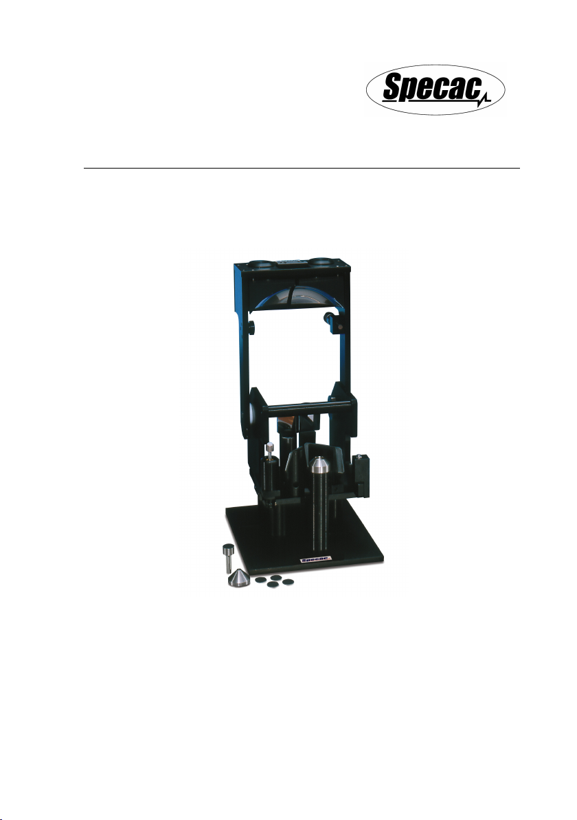
The Selector™
Diffuse Reflectance Accessory
User Manual
2I-19900 Issue 7


The Selector™
Diffuse Reflectance Accessory
User Manual
2I-19900 Issue 7

User Manual
2
The Selector™ Diffuse Reflectance Accessory
P/N GS19900
USER MANUAL- CONTENTS
1. INTRODUCTION ................................................................................. 3
2. UNPACKING AND CHECKLIST ............................................................. 5
3. SAFETY IN USE OF THE SELECTOR™ ACCESSORY ............................. 6
4. OPTICAL LAYOUT AND INSTALLATION OF THE SELECTOR™ ................. 7
L TO R SELECTOR™ ACCESSORY OPTICAL LAYOUT ........................... 7
R TO L SELECTOR™ ACCESSORY OPTICAL LAYOUT ......................... 10
INSTALLATION OF THE SELECTOR™ ACCESSORY ............................. 13
5. ALIGNMENT OF THE SELECTOR™ ACCESSORY ................................. 16
SAMPLE INTRODUCTION INTO THE SAMPLING CUP ............................ 16
FINE ALIGNMENT - FINAL OUTPUT MIRROR ADJUSTMENT ................. 18
OUTPUT ELLIPSOID MIRROR E2 ADJUSTMENT.................................. 21
MICROMETER SCREW ADJUSTMENT ................................................ 22
6. SAMPLE ANALYSIS .......................................................................... 24
SAMPLE CUP OPTIONS ................................................................... 24
11MM DIAMETER STANDARD SAMPLE CUP....................................... 24
4MM DIAMETER MICRO SAMPLE CUP ............................................... 25
DIABRAZE PAD AND DIABRAZE PAD MOUNT HOLDER ........................ 25
TILTED (TOTAL REFLECTANCE) SAMPLE CUP .................................. 27
PROCEDURE FOR SAMPLE MEASUREMENTS .................................... 28
USING A SAMPLE CUP OPTION ........................................................ 28
USING A DIABRAZE PAD OPTION ..................................................... 29
7. CARE AND MAINTENANCE ................................................................ 31
8. LEGEND FOR THE SELECTOR™ ACCESSORY .................................... 32
9. SPARE PARTS FOR THE SELECTOR™ .............................................. 33
10. SELECTOR™ BASEPLATE INSTALLATION GUIDE.............................. 34
© April 2016 Specac Ltd. All rights reserved.
Brilliant Spectroscopy is a trademark of Specac Ltd.
Other product names mentioned herein may be trademarks
of their respective owners.

Selector™ Diffuse Reflectance Accessory
3
1. Introduction
Thank you for purchasing a Specac product.
Infrared radiant light when reflected from a solid surface can be either
diffuse, specular or both (total reflectance) in nature.
Diffuse reflectance is based upon the collection of radiation that has
been diffusely scattered from the sample. From illumination by
infrared radiation of a solid sample surface that can deemed non linear
or irregular (e.g. powdered, granular or fabric/textile type samples),
although there will be components of some specularly reflected light
from the surface, the majority of light to collect for measurement will be
diffusely scattered.
The Selector™ accessory P/N GS19000 uses an optimized off-axis
optics configuration which selectively collects and maximizes the
diffusely reflected components of light, whilst minimizing the specular
component. The off-axis design also allows for the expansion of use of
the Selector optics with alternative specialized baseplates such as the
Environmental Chamber (P/N GS19930).
The Selector™ accessory is provided with a range of sampling cups
for appropriate sample study which include a standard 11mm diameter
cup, a micro 4mm diameter cup and a tilted cup. The tilted cup can be
used for the collection of total reflectance (diffuse and specular
components of light) spectra, if desired. In addition, there are also
abrasive sample mounts for use with 12mm diabraze pads. The
diabraze material is rubbed against the surface of an intractable solid
to deposit a small amount of the solid on the abrasive pad surface. The
diabraze pad, on the sample mount, is then placed into the sampling
position post of the Selector™ accessory.
The design of Selector™ accessory for the arrangement and infrared
light beam passage sequence for its optical mirror components means
that it is a beam direction dependant accessory for correct
installation into a spectrometer system. A left to right or right to left
beam direction (source to detector) as it passes through the

User Manual
4
spectrometer sample compartment means a Selector™ accessory will
only fit on to its appropriate beam direction dependant baseplate. The
Selector™ accessory can be installed into different spectrometer
systems by change of an appropriate baseplate, but the spectrometer
systems themselves must have the same common left to right or right
to left beam direction.
If you are in doubt as to whether your particular build of Selector™
accessory may be suitable for use and installation into a specific
spectrometer system, please contact Specac for advice.
Selector™ Accessory (in Right to Left Beam Build Configuration)

Selector™ Diffuse Reflectance Accessory
5
2. Unpacking and Checklist
On receipt of your Selector™ accessory please check that the
following have been supplied: (The Selector™ accessory will be
supplied in its own carry case.)
1 Selector™ optical unit assembly in left to right or right to left
beam direction configuration.
1 Selector™ baseplate fitted with 4 support posts in left to right or
right to left beam direction configuration (for your make and model
of spectrometer)
1 Sample holder post (already fitted to the Selector™ baseplate on
some versions – simply screws into position).
1 Micro sample cup (4mm dia x 2.5mm deep).
2 Standard sample cups (11mm dia x 2.5mm deep).
1 Tilted cup. (For total reflectance measurement.)
2 Abrasive sampler (diabraze pad) mounts.
1 Packet of self-adhesive diabraze pads (20pads - 12mm dia).
1 Extended ‘T’ bar Allen key.
1 Allen Key 1.5mm A/F
1 Allen Key 2.0mm A/F
1 “Tommy Bar” (metal rod) for mirror adjustment
Baseplate fixing screws and washers (where necessary).
Carefully remove the Selector™ optical unit assembly, its baseplate
and associated components from the carry case in preparation for
installation into the spectrometer.

User Manual
6
3. Safety in Use of the Selector Accessory
There are no specific precautions to be taken when the optical unit
assembly of the Selector™ accessory is being used on its own
standard Selector™ baseplate and sampling cups or diabraze sample
pads, other than those associated safety procedures you may need to
adopt for a specific sample type. (e.g. if the sample is toxic or
hazardous, etc), as the sample for analysis is exposed to the local
environment.
Warning!
If you are to use the optical unit assembly of the Selector™
accessory on the baseplate of the complimentary
Environmental Chamber accessory (P/N GS19930), along
with any considerations that may be required for safe
handling of the sample itself, the recommended operating
safety procedures found from the Environmental Chamber
instruction manual, must be followed.
With the combination of Selector™ optical unit affixed to the
Environmental Chamber accessory, an appropriate sample can be
measured for diffusely reflected scatter of light at elevated
temperatures (up to 800°C) and pressures (up to 500psi). The
sampling post position of a standard Selector™ baseplate assembly
that accepts the individual sampling cups and diabraze sample pads of
the standard Selector™ accessory is effectively replaced by an
environmentally controllable chamber, whereby the sample for analysis
is placed into an enclosed heatable cup and covered by a pressure
certified window cap assembly. As standard the window material for
the pressure certified window cap assembly is zinc selenide (ZnSe).
Further information for the Environmental Chamber accessory is found
within its own instruction manual.
Selector™ Diffuse Reflectance Accessory
7
4. Optical Layout/Installation of the Selector™
The Selector™ accessory is a beam direction dependent accessory
whereby infrared light radiation passes from the source to the detector
of a spectrometer through the sample compartment area from a left to
right (L to R), or right to left (R to L) orientation, as viewed from the
front or above the spectrometer.
L to R Selector™ Accessory Optical Layout
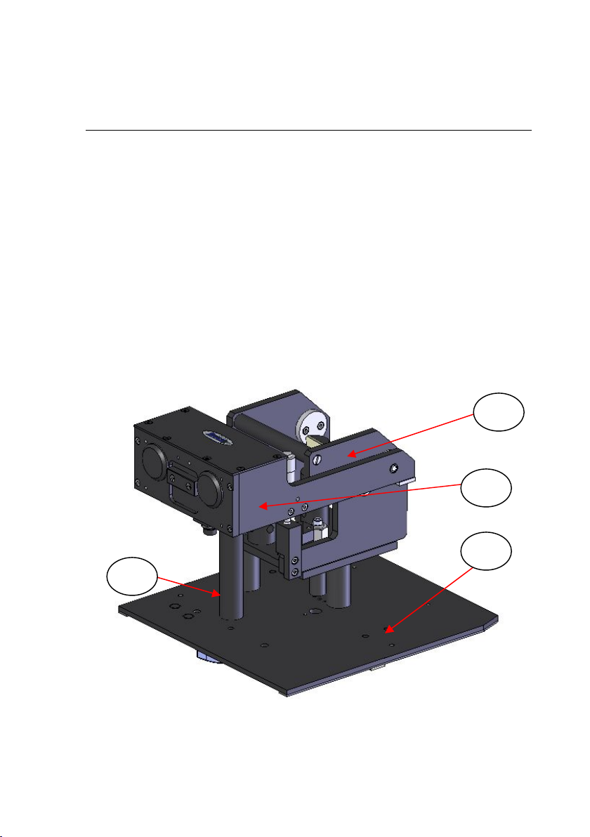
Fig 1 shows an L to R beam Selector™ optical unit (1) when fitted to
its corresponding L to R Selector™ baseplate assembly (2) and in the
Operating Position. In this case for Fig 1, the combination of the parts
as shown forms the Selector™ accessory that can be used in a Perkin
Elmer Spectrum One spectrometer.
Fig 1. L to R Beam Selector™ Accessory Fitted to an appropriate
L to R Beam Baseplate (e.g. for Perkin Elmer Spectrum One)
1
2
3
4
User Manual
8
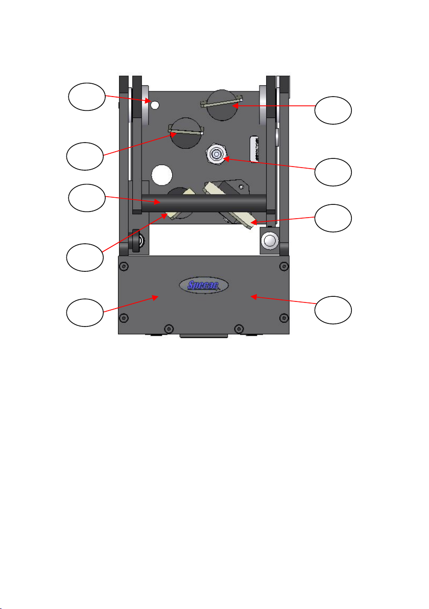
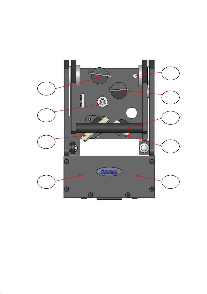
Fig 2. Top View of L to R Beam Selector™ Optical Unit
Fig 2 shows a top view of an L to R Selector™ optical unit alone and
Fig 3 shows the same L to R Selector™ optical unit but from the
underside. From the Figs 2 and 3, the light beam sequence for
passage of light through the Selector™ optical unit for an L to R
direction is as follows:-
The light beam from the source is directed to a fixed angled mirror (5)
on its mount post and onto another fixed angle mirror (6) on its mount
post. The light beam is then projected to an input ellipsoid mirror E1
(7) which then focuses the light onto the surface area of a sample held
in a cup that is positioned on top of the sample post (3) – see Fig 1. (In
Fig 2 the E1 mirror (7) has been indicated, but it is positioned
underneath the top cover of the ellipsoid mirrors arm assembly (4) –
see Fig 1.) It is easier to see E1 (7) from the underside view of Fig 3.
6
5
7
9
11
10
8
13
18

Selector™ Diffuse Reflectance Accessory
9
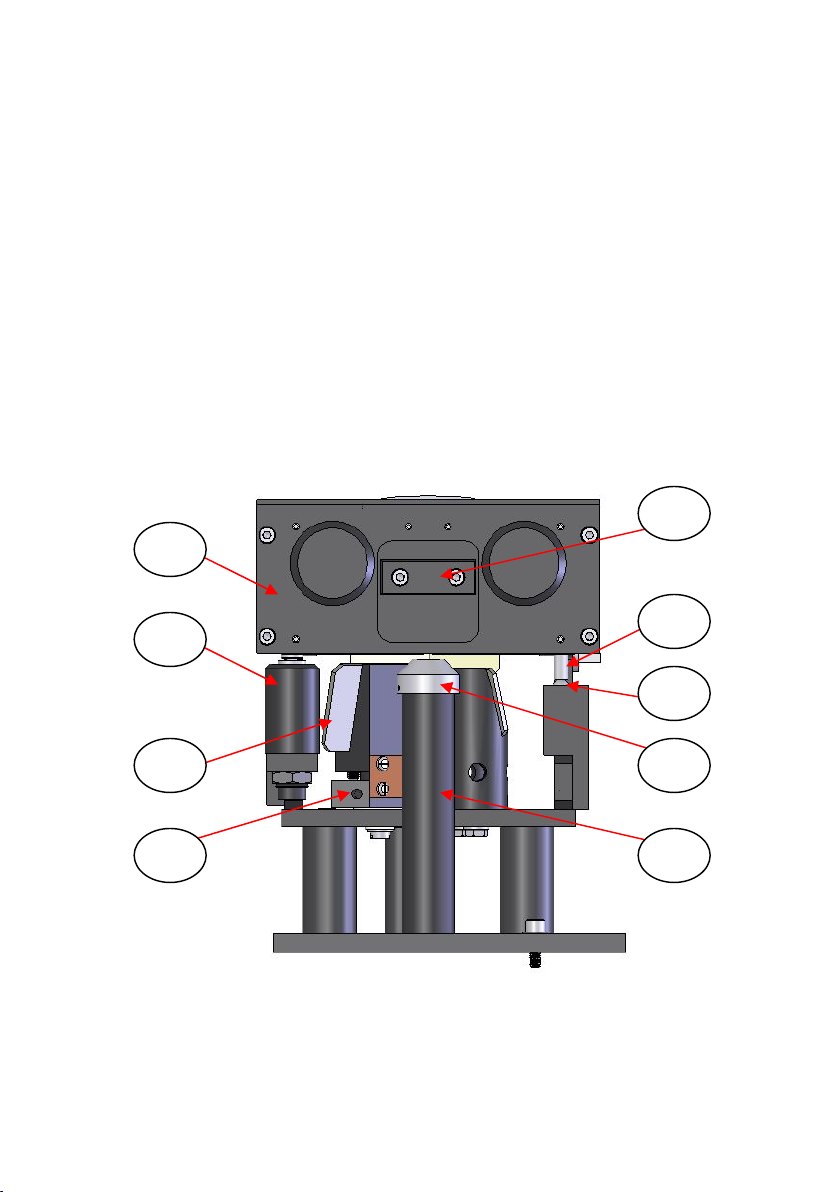
Fig 3. Underside View of L to R Selector™ Optical Unit
At the sample surface (e.g. a powder sample contained in a sample
cup) the incoming light from E1 (7) will be scattered and it is the
diffusely reflected component of this scattered light that is collected by
the output ellipsoid mirror E2 (8).
Note: The “off axis” design for both E1 (7) and E2 (8) mirrors being
forward and on the same side of the sampling surface area
means that when a flat, horizontal sample surface cup is used,
then only diffusely reflected light will be collected by the E2
(8) mirror. Any specularly reflected component of incident
light is lost to the system.
7
12
13
8
11
User Manual
10
After the scattered light has been collected by the E2 (8) mirror, the
light is focused towards a fixed mirror (9) on its sample mount which
then deflects the light to a movable (for rotation and tilt) mirror (10) on
its mount. The light beam can then be deflected precisely to the
detector of the system.
In summary, the beam sequence for an L to R Selector™ as indicated
for the mirrors from Figs 2 and 3 is:-
Source – (5) – (6) – (7) – Sample – (8) – (9) – (10) – Detector.
R to L Selector™ Accessory Optical Layout
Fig 4 shows an R to L beam Selector™ optical unit (1) when fitted to
its corresponding R to L Selector™ baseplate assembly (2) and in the
Operating Position. In this case for Fig 4, the combination of the parts
as shown forms the Selector™ accessory that can be used in a variety
of Nicolet Spectrometers (Nexus, Avatar, iS10, etc).
Fig 4. R to L Beam Selector™ Accessory Fitted to an Appropriate
R to L Beam Baseplate (e.g. for Nicolet iS10)
3
1
4
2
Selector™ Diffuse Reflectance Accessory
11
Accordingly, similar to an L to R Selector™, Fig 5 shows a top view of
an R to L Selector™ optical unit alone and Fig 6 shows the same
R to L Selector™ optical unit but from the underside.
Fig 5. Top View of R to L Beam Selector™ Optical Unit
From the Figs 5 and 6, the light beam sequence for passage of light
through the Selector™ optical unit for an R to L direction is as follows:-
The light beam from the source is directed to a fixed angled mirror (5)
on its mount post and onto another fixed angle mirror (6) on its mount
post. The light beam is then projected to an input ellipsoid mirror E1
(7) which then focuses the light onto the surface area of a sample held
9
11
10
8
6
5
7
13
18

User Manual
12
in a cup that is positioned on top of the sample post (3) – see Fig 4. (In
Fig 5 the E1 mirror (7) has been indicated, but it is positioned
underneath the top cover of the ellipsoid mirrors arm assembly (4) –
see Fig 4.) It is easier to see E1 (7) from the underside view of Fig 6.
Fig 6. Underside View of R to L Selector™ Optical Unit
At the sample surface (e.g. a powder sample contained in a sample
cup) the incoming light from E1 (7) will be scattered and it is the
diffusely reflected component of this scattered light that is collected by
the output ellipsoid mirror E2 (8).
8
11
7
12
13

Selector™ Diffuse Reflectance Accessory
13
Note: The “off axis” design for both E1 (7) and E2 (8) mirrors being
forward and on the same side of the sampling surface area
means that when a flat, horizontal sample surface cup is used,
then only diffusely reflected light will be collected by the E2
(8) mirror. Any specularly reflected component of incident
light is lost to the system.
After the scattered light has been collected by the E2 (8) mirror, the
light is focused towards a fixed mirror (9) on its sample mount which
then deflects the light to a movable (for rotation and tilt) mirror (10) on
its mount. The light beam can then be deflected precisely to the
detector of the system.
In summary, the beam sequence for an R to L Selector™ as indicated
for the mirrors from Figs 5 and 6 is:-
Source – (5) – (6) – (7) – Sample – (8) – (9) – (10) – Detector.
Installation of the Selector™ Accessory
The Selector™ optical unit (1) is mounted onto a baseplate (2) to
provide high stability when installed into the spectrometer. Initially, the
spectrometers own sample mount and/or sample compartment (if this
is part of the spectrometer’s design) will have to be removed before the
Selector™ accessory can be installed. The L to R or R to L Selector™
optical unit (1) is supplied with an appropriate baseplate (2) and the
necessary fixing screws specifically for the spectrometer into which it is
to be installed and used.
Some spectrometer systems (such as Mattson, Bruker and Nicolet
500/700 Series instruments) require the baseplate (2) to be installed
into the sample compartment before the Selector™ optical unit (1) is
attached to the baseplate (2). For other spectrometers, the Selector™
optical unit (1) can be mounted on the baseplate (2) prior to installation
in the sample compartment.
For installation of the Selector™ baseplate (2) itself into a specific
spectrometer (with or without the Selector™ optical unit (1) fitted),
please see the Installation Guide in Section 10) of this manual.

User Manual
14
Attachment of the Selector™ Optical Unit (1) to the Baseplate (2)
It can be seen by comparison of the build of Selector™ accessory that
an R to L beam direction version is a reversed “mirror” image of an
L to R beam direction version for positioning of the mirror components.
On the Selector™ optical unit base (for both L to R and R to L
versions) there is a central fixing M4 x 25mm captive screw (11). There
is also a slot hole (12) and circular hole (13) on the Selector™ optical
unit base. (See Figs 3 and 6.) From the combination of fixing screw
(11) and location holes (12) and (13), an L to R or R to L Selector™
optical unit is fitted to its appropriate baseplate. Similar to the mirrors,
the fixing hole positions on the Selector™ optical unit base and central
fixing screw for attachment to the specific L to R or R to L baseplate
are also in a reversed mirror image configuration.
For attachment of the Selector™ optical unit (1) to its baseplate (2)
carefully lift the Selector™ optical unit by the lifting handle (18) - see
Figs 2 and 5 - and position over the baseplate (2) – see Figs 7 and 8.
Note: It is best to have the Selector™ ellipsoid mirrors arm assembly
(4 in the down/closed (Operating Position) such that you can
see the locating holes (12 and 13) and fixing screw (11) of the
Selector™ optical unit, to match them up to the baseplate posts.
Align the slot hole (12) with the front support post (15) stud and the
circular hole (13) with the rear support post (16) stud of the baseplate
(2) and push the optical unit (1) onto the baseplate such that the
optical unit is also supported on the third post (17) of the baseplate.
Note: The locating holes and post studs will be on the left hand side of
the optical unit base for an L to R beam direction accessory and
on the right side of the optical unit base for an R to L beam
direction accessory. You cannot fit an L to R beam direction
Selector™ optical unit to an R to L beam direction baseplate (or
vice versa). The sample post (3) should be to the front of the
baseplate near to and underneath the ellipsoid mirrors (7, 8).
Using the extended ‘T’ bar Allen key supplied, carefully screw the
captive fixing screw (11) into the middle pillar (14) on the baseplate.

Selector™ Diffuse Reflectance Accessory
15
Gently tighten to secure the Selector™ optical unit (1) to the baseplate
(2), but do not overtighten the fixing screw (11). The optical unit base
underside should not actually touch the top of the middle pillar (14).
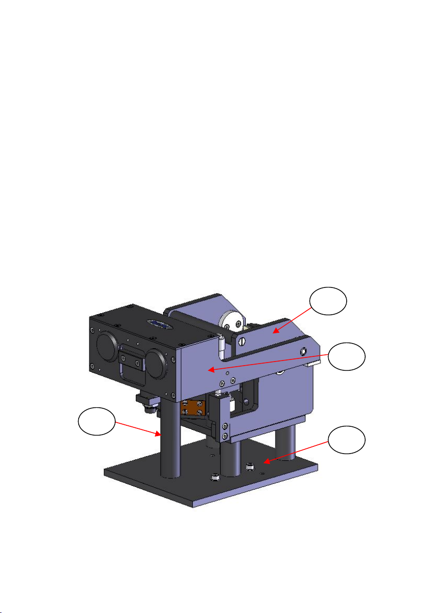
Fig 7. L to R Selector™ Baseplate (Perkin Elmer Spectrum One)
Fig 8. R to L Selector™ Baseplate (Nicolet Avatar, Nexus, iS10)
3
17 14
16
15
3
15
16
14
17

User Manual
16
5. Alignment of the Selector™ Accessory
The Selector™ diffuse reflectance accessory has been pre-aligned
before leaving Specac and will only require minor adjustment to some
of the parts to maximize the light beam throughput when the accessory
is installed in your spectrometer.
Note: Usually, only the output ellipsoidal mirror E2 (8) and final output
mirror (10) that are adjustable may need to be altered for their
settings to obtain an optimum light throughput on your
spectrometer. The mirrors (8) and (10) will be on the left side of
the optical unit (1) looking from above for a spectrometer with an
R to L beam direction and on the right side for a spectrometer
with an L to R beam direction.
Specifically, if you have a Selector™ accessory for use in a Perkin
Elmer Spectrum 2000 (GX) spectrometer, the initial input (5) and final
output (10) mirrors on the optical unit (1) are both adjustable for
rotation and tilt. This is because the Spectrum 2000 (GX) spectrometer
can be used with an L to R or R to L beam direction depending on the
position of the sampling compartment and detector system to the light
source” unit. Although the input (5) and output (10) mirror assemblies
look similar, there is a difference in the fixed angled face of the mirrors
on their adjustable mounts. Hence, you will have been provided with a
specific L to R or R to L beam direction Selector™ optical unit (1) that
will only affix to the appropriate L to R or R to L baseplate (2) for your
configuration of Perkin Elmer Spectrum 2000 (GX) spectrometer.
Sample Introduction into the Sampling Cup
Having installed the Selector™ optical unit (1) into the spectrometer via
its appropriate baseplate (2), before fine alignment and operation of
the Selector™ accessory can be carried out, a representative test
sample must be placed into position. One of the choice of sampling
cups, or a diabraze pad on its support holder that have been provided
with the Selector™ accessory can be used for positioning on the top of
the sample post (3). (Please refer to Section 6 of this manual to explain
about the sampling cups and diabraze pad sampling options.)
Selector™ Diffuse Reflectance Accessory
17
Ground spectroscopic grade KBr or KCl powder is recommended for
use as a reference material for alignment and background spectra. The
powder can be placed into the 11mm diameter sample cup (19) that is
mounted on the top of the sample holder post (3). (See Fig 9.)
Tip: It is best to fill the sample cup away from the optical unit (1) and
spectrometer in case of accidental sample spillage.
Note: For the purposes of explanation for the alignment procedure an
R to L Selector™ accessory is used in the following diagrams. If
you have an L to R Selector™ accessory the same steps for
alignment are followed but the mirrors (8) and (10) for any
adjustments are reversed for their positions as shown on the
L to R built Selector™ accessory.
Fig 9. Front View of R to L Selector™ Accessory in Operating
Position (Ellipsoid Arm Assembly Down/Closed)
24
19
3
4
25
26
27
28
10

User Manual
18
Taking the standard 11mm diameter sample cup, fill it with finely
ground KBr or KCl powder. When filled, carefully flatten the top surface
of the powder with a piece of glass or polished metal, so that is level
with the top edge of the sample cup (19).
Raise the ellipsoid mirrors arm assembly (4) by the recessed finger
handle (24) on the Selector™ optical unit (1) to its up/open Sample
Loading Position. When the ellipsoid mirror arm assembly (4) has
been raised upright, it will remain in position. (See Fig 10.)
Place the KBr or KCl filled sample cup (19) carefully onto the top of the
sample holder post (3). Try to avoid any spillage of the flattened
sample powder when fitting the cup (19) to the post (3).
Lower the ellipsoid mirrors arm assembly (4) back to its down/closed
Operating Position so that the height adjustment micrometer screw
(25) rests on the steel ball stop (26). (See Fig 9.) A shock absorber
(27) is fitted to ensure that the ellipsoid mirrors arm assembly (4)
comes to rest gently on the steel ball (26) without damaging the
micrometer (25).
With the ellipsoid mirrors arm assembly (4) closed the beam sequence
through the Selector™ optical unit (1) should be completed and at this
stage some energy throughput from diffusely collected light off of the
sample surface should be observed by the spectrometers own
detection system.
Fine Alignment – Final Output Mirror (10) Adjustment
When the sample cup (19) with sample is in position and there is some
energy throughput being measured by the spectrometers detection
system, then fine alignment of the optics that are adjustable can be
carried out to “peak up“ the throughput signal.
Firstly, the final output mirror (10) should be adjusted to try and
improve the throughput signal. The “Tommy bar” supplied enables
rotational adjustment of the final output mirror (10). Insert the “Tommy
bar” from the front of the Selector™ accessory into the hole in the base
(28) of the final output mirror mount (10). (See Fig 9.) Carefully move
the “Tommy bar” horizontally in a left or right direction to improve the
throughput energy signal value. If the movement in one direction
Table of contents
Other Specac Laboratory Equipment manuals

Specac
Specac APEX QUICK RELEASE DIE User manual

Specac
Specac Storm 10H User manual

Specac
Specac Gateway ATR User manual

Specac
Specac GS12000 Series User manual

Specac
Specac Quest User manual

Specac
Specac Quest ATR GS10800 Series User manual

Specac
Specac Golden Gate GS10500 Series User manual

Specac
Specac Gateway ATR User manual

Specac
Specac Quest User manual

Specac
Specac Golden Gate GS10640 User manual


