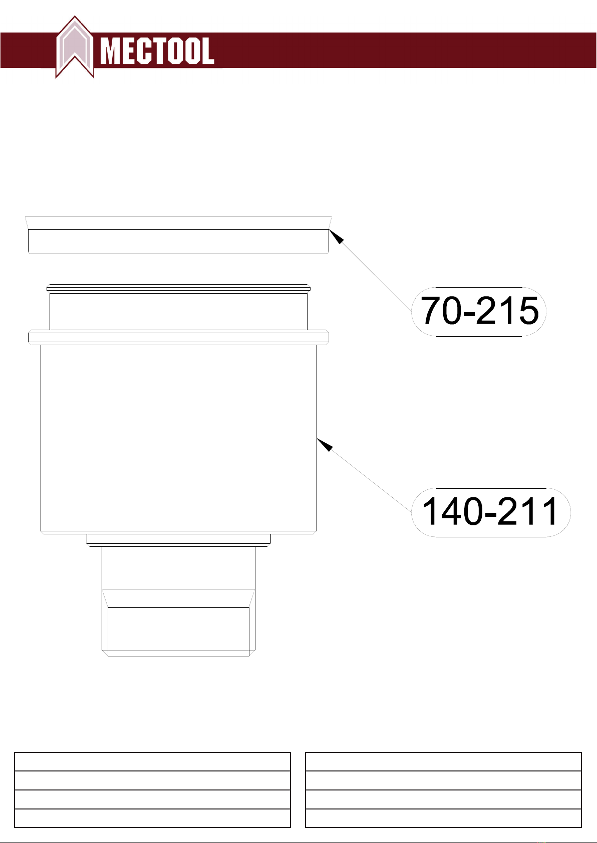
Model Quantity Metric Inch
TP3 4 M8 5/16
TP10 4 M8 5/16
TP40 2 M10 3/8
TP70 6 M8 5/16
TP140 6 M8 5/16
1. Rigidly mount the Transporter to a solid surface using
these recommended bolt sizes:
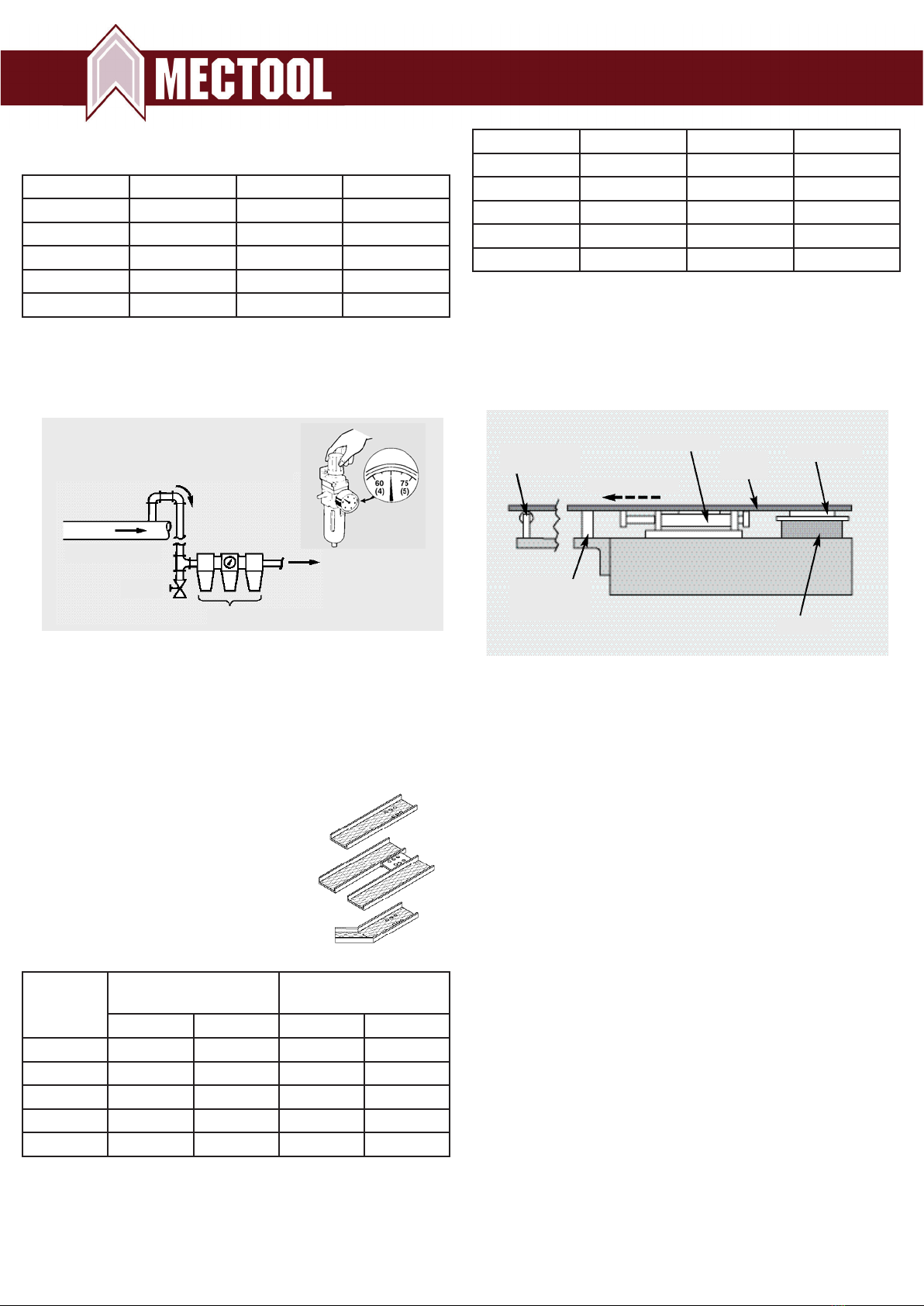
Recommended Air Line
Connection to Eliminate Moisture
and Particles from Main Line
3. Fill the lubricator with a good grade of hydraulic oil such
as Shell Tellus 32 or equivalent. Set the lubricator for
one (1) drop per minute.
4. Connect the air line with exible poly-ow tubing into the
threaded inlet. On model TP3 use 1/4” tubing for 1/8” NPT.
Models TP10, TP40, TP70 and TP140 use
3/8” tubing for 1/4” NPT.
5. A custom ”U” prole tray or chute
must be designed to handle each
specic application or tool. Any
material can be used but we
recommend aluminum or any light
gauge material to reduce tray weight.
Maximum tray weight should not
exceed the following table data:
2. Air line requires use of an oil mist-type combination
lter/regulator/lubricator, and pressure gauge. Set pressure
to 4-5 bar (60-75 psi). Do not exceed 5.5 bar (80 psi) as
excess pressure will damage the Transporter.
Main Air Line
Drain
To Transporter
Filter/Regulator/Lubricator
Model Max. weight
tray only
Max. weight
of parts
Kg Lbs. Kg Lbs.
TP3 1,5 3,3 3 6,6
TP10 3 6,6 10 20
TP40 15 33 40 80
TP70 50 110 70 140
TP140 100 200 140 300
6. Fasten the tray or chute to the Transporter with metric
screws at all holes. Be sure to use spacers or washers
between the Transporter and the tray to reduce contact friction
between the moving tray and the Transporter body.
Refer to the following table:
Model Quantity Screw size Depth
TP3 6 M6 8 mm
TP10 6 M6 8 mm
TP40 6 M8 9 mm
TP70 6 M8 8 mm
TP140 6 M8 8 mm
7. The conveyor tray or chute must be supported at both ends
to minimize vibration and deection. A block of Delrin GP-500
or Nylon, low friction material can be used for the tray to slide.
Ball bearing
roller
TransporterChute
or tray
Roller slide
Spacer
Press bolster
Solid slide -
Low Friction
Material
Feed Direction
8. The speed adjustment is preset at the factory with the
correct frequency for a lightweight tray or chute. The speed
can be adjusted by turning the screw or knob clockwise to
decrease the movement on the models TP3, TP10 and TP40.
The TP70 and TP140 are adjusted by turning the screw or
knob counter-clockwise to decrease the movement.
Maximum speed is not required to move parts or scrap
eciently.
9. If the TP40 speed frequency is inadequate, release the
air regulator rod 40-029 and gently push forward to increase
speed or backwards to decrease.
10. The TP10 may require a slight adjustment to maintain
proper speed frequency after a period of operation.
If speed adjustment screw 10-405 does not slow the unit
suciently, it may be necessary to slightly snug the two
screws at the air regulator valve 10-603. This reduces the air
being released from the valve and decreases speed.
Snugging the screws too tightly will cause bending of the air
regulator rod and poor performance.
11. Spray the same Tellus oil used in lubrication on the
pistons every week.
12. If there is a build-up of sticky oil on the conveyor tray or if
the scrap parts are very oily, they may stick to the surface and
reduce movement. To reduce friction, try dimpling the surface
of the conveyor chute with a ballpeen hammer or use a
dierent material like expanded metal or proled, roll-formed
material.
Installation