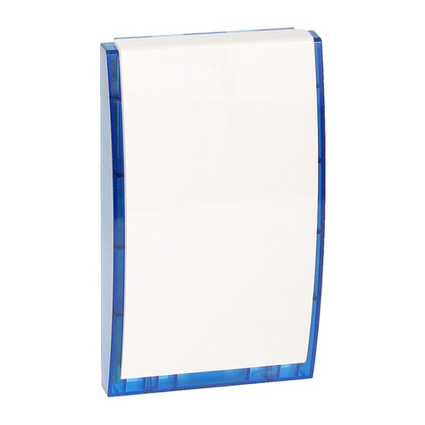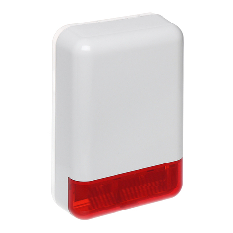
SPL-5020 - 2 - SATEL
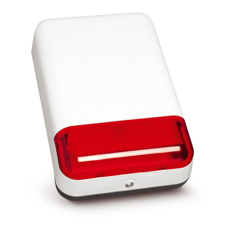
The siren is designed for work both with or without a 12V/0.8Ah battery installed (own power supply).
Battery should be connected to the BATTERY connector on PCB. If there is a battery installed, the
supply voltage should be within the range of 13V to 13.8V, so that the proper charging process can be
ensured. The siren supply voltage is to be connected to the terminals +12V and GND. Voltage loss
across these terminals (with the siren battery connected) will set off the acoustic alarm for a period of
maximum 6 minutes. An earlier restoration of supply will stop the alarm signaling. It should be borne
in mind that the current output of the alarm control panel must be sufficient for correct operation of the
device.
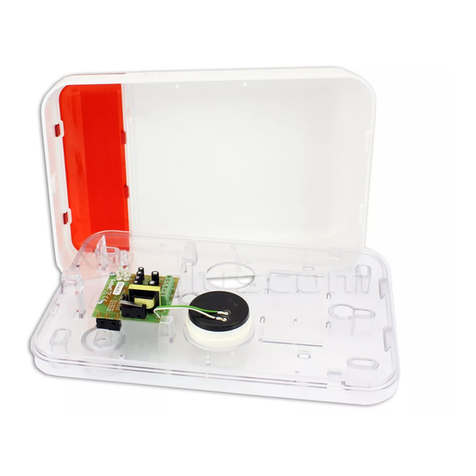
The tamper circuit of the siren reacts to removal of the outer shell as well as pulling the device off the
wall. To make the functional test of the pull-off alarm possible, there must be the "S" element screwed
down to the surface (Fig. 1).
The "TMP" terminals are used to connect the siren to the security system tamper circuit.
4. TECHNICAL DATA
Supply voltage, rated – siren without back-up battery......................................................12V DC ±15%
Supply voltage – siren with back-up battery.....................................................................13...13.8V DC
Current consumption – acoustic signaling ..................................................................................200mA
Average/max. current consumption – optical signaling...................................................350mA/500mA
Back-up battery (recommended) ...........................................................................................12V/0.8Ah
Battery charging current................................................................................................approx. 100mA
Battery protection..............................................................................................................fuse T 3.15A
Sound intensity............................................................................................................... approx. 120dB
Working temperature..................................................................................................... -35oC…+60oC
Dimensions ..................................................................................................................298x197x72mm
Weight........................................................................................................................................... 757g
SATEL sp. z o.o.
ul. Schuberta 79
80-172 Gdańsk
POLAND
tel. +48 58 320 94 00
info@satel.pl
www.satel.pl
Latest EC declaration of conformity
and product approval certificates
can be downloaded from our Web
site www.satel.pl
JP1 – acoustic signaling
JP2 – optical signaling
H– triggering with 12V voltage
L – triggering by shorting to COM (0V)
JP2 JP1
H
L A
H
L
O
Figure 2. Jumper settings
AC AC OUT1 COM OUT2 OUT3 +12V COM
ALARM CONTROL PANEL (example)
Figure 3. Example of siren connection to control panel outputs (high- and low-current)
SPL-5020 SIREN
SO – optical signaling
SA – acoustic signaling
TMP – tamper circuit
+12V GND SO SA TMP TMP
TO TAMPER CIRCUIT OF THE ALARM CONTROL PANEL
OUT1 – high-current output which triggers the
acoustic alarm signaling by direct supply of
+12V voltage to the SA terminal.
OUT2 – OC type low-current output which triggers the
optical alarm signaling by shorting the SO
terminal to COM (0V).

