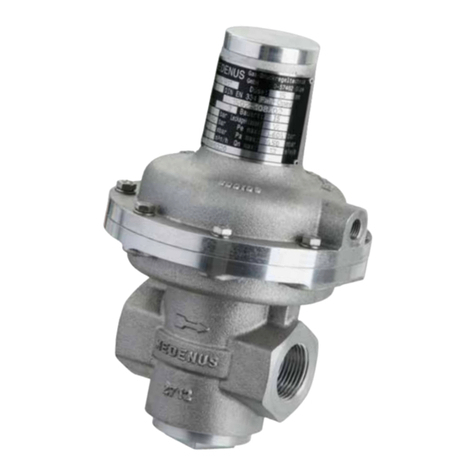
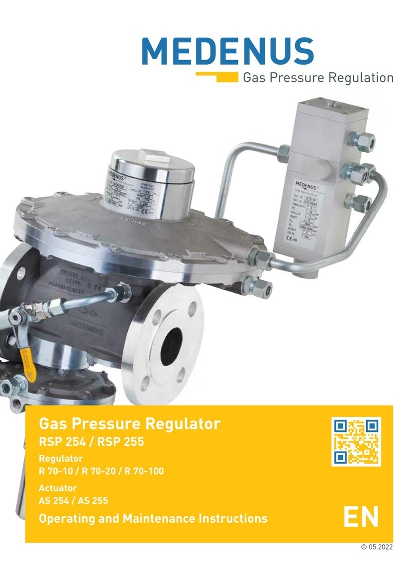
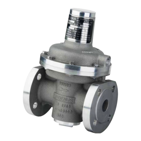
MEDENUS R 100 Manual

© 05.2022
Gas Pressure Regulator
R 100 / R 100U
Accessories / Options
Operating and Maintenance Instructions

Subject to technical modifications! Reprint prohibited!

Actuator housing
Double seat valve
Main diaphragm
Diaphragm assembly
shown R 100 R 100 U is shown
Design of the gas pressure regulator R 100 / R 100U

Table of Contents
1 General Information 6
1.1 Warranty and Liability 6
1.2 Symbols, Notes 7
1.3 Terms, Abbreviations 7
2 Application, Characteristics 8
2.1 Application 8
2.2 Characteristics 8
2.3 Types of Models (Options) 8
3 Avoidance of Foreseeable Misuse 8
4 Safety Instructions 9
4.1 Hazards of Handling the Device 9
4.2 Personnel Requirements 9
4.3 Country-Specific Requirements 9
4.4 Handover of the Operating and Maintenance Instructions 9
4.5 Safety in Operation 10
4.6 What to Do in Case of Danger 10
5 Responsibility of the Operator 10
6 Transport, Storage and Packaging 11
6.1 Transport 11
6.2 Storage 11
6.3 Packaging 11
7 Mounting and Commissioning 12
7.1 Safety Instructions and Preparation 12
7.2 Mounting 13
7.3 Leakage Test (Test for External Leakage) 14
7.4 Initial Commissioning / Recommissioning 15
7.5 Control Spring Setpoint Table 16
7.6 Decommissioning 17
8 Maintenance 18
8.1 Maintenance Plan 18
8.2 Maintenance Procedure 18
8.3 Table of Screw Tightening Torques MA 19
8.4 Lubricants Table 19
9 Troubleshooting 20
9.1 Gas Pressure Regulator 20
10 Replacement and Disposal 21
11 Spare Parts 22
11.1 Spare Parts Drawing 22
11.2 Optional Spare Parts Drawing 22
11.3 Parts for Maintenance Work 23
Main diaphragm and O-ring R100 / R100-U 23
Valve plate R100 / R100-U (standard e.g. VT-102 / Viton e.g. VT-102-V) 23
O-rings and sealing rings R100 / R100-U 24
Valve plate set tripod R100 / R100-U 24
Notes 25

12 Accessories / Options 26
12.1 High-pressure spindle 26
12.2 RSD restrictor valve 27
12.3 Safety diaphragm 28
13 Tools 29
13.1 Brace and bit with 4-jaw chuck29
13.2 SSV tightening tool 29
Declaration of Conformity 30

6
© 05.2022
1 General Information
The personnel entrusted with installation, operation or maintenance of the gas pressure regulator must
have completely read and understood beforehand the following documents:
• Gas Pressure Regulator R 100 / R 100U Product Information
The product information contains technical data, dimensions and a description of the design and the mode of
operation.
• Gas Pressure Regulator R 100 / R 100U Operating and Maintenance Instructions
This document allows safe and efficient handling of the device and contains information on assembly,
commissioning, maintenance, troubleshooting, and repair according to regulations.
It is an integral part of the scope of delivery of the device, must be kept in close proximity of the device and
must be readily accessible to personnel at any time.
The basic prerequisite for safe working is compliance with all safety instructions and instructions for action
given in this manual. Accordingly, the information and instructions must be observed when working on the
device or on the gas line. In addition, the local occupational safety regulations and general safety regulations
for the application range of the device shall apply.
The figures in these instructions are provided for basic understanding and may differ from the actual design.
The contents of these instructions are protected by copyright. They may be used as part of operating the
device. Any other use and/or reproduction is not permitted without prior authorization by MEDENUS Gas-
Druckregeltechnik GmbH.
1.1 Warranty and Liability
Claims under warranty or liability for personal injury and material damage are generally void
if one or several of the following conditions are not observed:
• Work on the device during the warranty period may only be performed in consultation with the manufacturer
• Designated use of the device in accordance with the established conditions of use
• Proper installation, commissioning, operation and maintenance of the device
• Operation of the device with properly installed and functioning safety devices only
• Operating and maintenance instructions of the device or of the system
• Compliance with the maintenance instructions
• Properly performed repairs
• Supply lines without defects
• The use of original MEDENUS©spare parts and lubricants listed in these instructions or
• Force majeure
It is generally prohibited
• To perform constructive modifications on the device
• To keep using the device despite the detection of a defect

7© 05.2022
1.3 Terms, Abbreviations
Terms and abbreviations are explained below:
1.2 Symbols, Notes
The instructions contain safety instructions marked with symbols to indicate possible consequences in case of non-
observance:
DANGER
Note
ATTENTION
This combination of symbol and signal word indicates a potentially hazardous
situation which, if not avoided, may result in minor or moderate injury, damage
to the device, the breakdown of the system, and material or environmental
damage.
This combination of symbol and signal word indicates an imminent hazardous
situation which, if not avoided, will result in death or serious injury.
This signal word highlights useful tips, recommendations, and information for
efficient and trouble-free operation.
ATC Acceptance test certificate
DN Nominal width
GPR Gas pressure regulator
MOP Maximum operating pressure
in a system
pdOutlet pressure
pds Setpoint of the
outlet pressure
SSV Safety shut-off valve
SRV Safety relief valve

8
© 05.2022
2 Application, Character-
istics
2.1 Application
Gas pressure regulator (GDR), direct-acting (operating without auxiliary power), for systems acc. to
DVGW work sheets G 491 (A) and G 600 (A) (TRGI)
Particularly suitable for dynamic regulation sections (e.g. gas fireplaces,
natural gas supply systems, burner circuits, gas motor operation)
Can be used as an equipment component on gas consumption facilities as defined in Regulation (EU) 2016/426.
Can be used for the gases defined in DVGW work sheets G 260 / G 262 and neutral non-aggressive gases.
(other gases on request)
2.2 Characteristics
• Integralpressure-tightmodel(IS)
• Pilotpressure-compensateddouble-seatvalve
• Highflowratecapacity
• Open-airmodel
3 Avoidance of Foreseeable Misuse
2.3 Types of Models (Options)
• Withthrottlevalve(RSD)fortheimpulselineonthediaphragmassembly
• Oxygenmodel
• WithFKMgaskets+stainlesssteelseat(e.g.forbiogasapplications)
• CoatingwithepoxyresininRALcolors
• Theregulatorsmustnotbeusedtocontrolliquids.
• Theregulatorsmustnotbeusedintemperaturerangesbelow-20°Corabove60°C
• Theregulatorsmustnotbeusedforpressurerangeshigherthanthepressure“PS“indicatedonthenameplate.
• The regulators may only be used for the gases specified under item 2.1 Application in these operating
instructions.
Other gases, such as oxygen or hydrogen, must be explicitly stated on the nameplate.
Please consult the manufacturer before use.
• Theregulatorsmustnotbeusedinhigh-temperatureareas(HTB)withoutanupstreamHTBfuse.

9© 05.2022
4 Safety Instructions
National accident prevention regulations and the system operator‘s safety regulations are not superseded by these
operating and maintenance instructions and must be taken into consideration with priority (in Germany, see, among
others, DVGW work sheets G 600, G 459/II, G 491 and G 495).
When performing work on the device, the current general and specific safety regulations must be observed.
The application limits of the device with respect to the medium, operating pressure and operating temperature can be
found on the nameplate affixed to the device or on the acceptance test certificate.
Using the device under different operating conditions must be agreed upon in consultation with
MEDENUS Gas-Druckregeltechnik GmbH.
The mechanical components of the device do not have any potential ignition sources of their own nor any hot surfaces
and are thus not covered by the scope of 2014/34/EU (ATEX). The electronic accessories used comply with the ATEX
requirements.
4.1 Hazards of Handling the Device
MEDENUS©devices conform with current standards and directives, the recognized technical rules and the recognized
safety rules.
However, improper use can result in hazards to the user or to third parties. This can also result in damage to the device
or to the system.
This is why the device may only be used:
• in accordance with its designated use
• in perfect condition
• while observing the notes given in these operating and maintenance instructions, and inspection and
maintenance regulations, which apply to the functioning and safety of the overall system.
Malfunctions or faults must be eliminated immediately.
4.2 Personnel Requirements
The device may only be mounted by qualified personnel.
Only authorized personnel with the required qualification is allowed to perform settings or repairs on the device.
4.3 Country-Specific Requirements
The rules and regulations applicable at the place of use must be observed and complied with. They apply to:
• gas lines, installation of the gas system
• gas supply
• work on the gas system
• accident prevention
4.4 Handover of the Operating and Maintenance Instructions
The supplier of the system shall hand over these operating and maintenance instructions to the operator of the system
no later than during commissioning and training of the operating personnel with the reminder to carefully store these
instructions.

10
© 05.2022
4.5 Safety in Operation
The device may only be used when all protective devices on the device or in the system are fully functional.
At least once a year, the device must be inspected for externally visible damage and for proper functioning
by a representative of the manufacturer or by a qualified person.
A more frequent inspection may become necessary, depending on the system conditions.
4.6 What to Do in Case of Danger
Information on what is to be done in case of danger and in case of accidents can be found in the respective operator's or
specialist companies' work instructions.
5 Responsibility of the Operator
Operator An operator is a person who operates the device himself/herself for commercial or economic purposes
or leaves it to a third party for use/application and is legally responsible for the safety of the user, the
personnel or third parties during operation.
The device is used in the commercial sector. The operator of the device is therefore subject to the legal
obligations for occupational safety. In addition to the safety instructions contained in these instructions,
the established maintenance intervals must be observed, taking into account the respective national
standard (alarm and hazard prevention plan).
In particular, the following applies:
• The operator is obliged to perform work on MEDENUS©devices during the warranty period only
after consultation with the manufacturer. Otherwise the claims under warranty will become
void.
• The operator must obtain information on the current occupational safety regulations and
determine additional hazards resulting from the special work conditions at the place of use of
the device in a risk assessment. The owner must implement the results in the form of operating
instructions for the device.
• During the entire time of use of the device, the operator must check whether the operating
instructions issued by him/her conform to the current state of the regulations and, if necessary,
adapt them.
• The operator must clearly regulate and define the responsibilities for installation, operation,
troubleshooting, maintenance and cleaning.
• The operator must ensure that all persons handling the device have read and understood these
instructions. In addition, the owner must train the personnel at regular intervals and inform
them about the hazards.
• The operator must make available to the personnel the required protective equipment and
oblige them to wear the required protective equipment.
• Moreover, the operator is responsible for the device always being in technically perfect condition.
Therefore, the following applies:
• The operator must make sure that the maintenance intervals described in these instructions
are observed.
• The operator must have all safety devices checked regularly for functionality and completeness.
Operator
duties

11 © 05.2022
6 Transport, Storage and Packaging
6.1 Transport
The device is delivered with flange protection caps. They must be removed prior to installation.
Make sure that the device is transported horizontally using suitable lifting gear. The device must be
handled carefully and secured against impacts and knocks.
In case of transport damage, we will require the following information from the nameplate affixed to
the device:
• Device type
• Device model
• Year of construction/fabrication number
Note
6.2 Storage
Equipment and spare parts must be stored under the following conditions:
• Do not store outdoors.
• Store in a dry and dust-free location.
• Store on a flat surface.
• Do not expose to aggressive media.
• Do not expose to ozone or ionizing radiation.
• Do not store adjacent to direct heat sources.
• Avoid mechanical vibrations.
• Storagetemperature:0to25°C.
• Relative air humidity: < 55 %.
Spare parts:
• Components susceptible to corrosion must be provided with a suitable preservative.
• Do not store O-rings and seals for more than 5 years even if stored properly.
• Spare parts must be stored in their original packaging until use.
Storage period for devices:
• Storage of the device for up to one year:
Store the gas pressure regulator in its original packaging and original condition at the time of supply. All
protective caps of the device must remain mounted.
• Storage of the device for more than 1 year (e.g. as a spare device):
Store the device in its original packaging and its original condition as delivered and check it for damage once
a year. Check the housing surface for dirt, damage and corrosion. If necessary, clean all external parts. After
5 years, all O-rings and seals must be replaced.
6.3 Packaging
• The individual packaged items have been packaged in view of the transport conditions to be expected.
• The symbols on the packaging must be observed during transport and storage.
• Only environmentally friendly materials have been used for packaging.
• The packaging is designed for protecting the individual components from transport damage, corrosion and
other damage until mounting. This is why the packaging must not be destroyed and only removed just prior to
mounting.

12
© 05.2022
7 Mounting and Commissioning
7.1 Safety Instructions and Preparation
Prior to starting work on pressurized components:
• Close all connections to the gas line.
• Depressurize all pressurized components. Also discharge residual energies.
• Defective components charged with pressure in operation must be replaced immediately by
an appropriate expert.
Prior to starting work, ensure sufficient clearance for mounting.
Before installing the device, check whether the performance data (nameplate) and the scope of
delivery coincide with the order or the system data, i.e., make sure that the provided devices are
suitable for their intended purpose. In particular, the inlet pressure of the system must be lower than
the maximum allowable pressure of the device.
Direct contact of gas valves and fittings, i.e., the control system, with hardening masonry, concrete
walls or floors is not permitted. Provide suitable supports, working materials and protective
equipment.
Take into account the minimum clearances for maintenance as stated in the product information.
Before installing the device in the pipeline, check whether a shut-off device that interrupts the gas
flow supply to the device has been mounted upstream and downstream of the device to be installed.
Prior to commissioning, make sure that all installation work has been carried out and completed
in accordance with the data and information given in these instructions and that no unauthorized
persons stay in the danger zone.
DANGER
Note
Note
DANGER
Note
Note
Note
7.2 Mounting
• Remove the packaging, flange protection caps and shipping braces.
• Check the device for wear and damage.
• Make sure that the device is installed free of stress. Make sure to observe the direction of flow
i.e., the arrow on the housing must point in the direction of flow.
• All breather lines (items 7.04 / 7.07) must be vented to the outside atmosphere.
• The breather line (item 7.04) may not be required if breather valves are used
Gas pressure regulators Flange tightening torques
Screw size Screw tightening
torque MA
Screw size Screw tightening
torque MA
M6 8Nm M12 60Nm
M8 18Nm M16 120Nm
M10 36Nm M20 190Nm
M12 62Nm
Tightening torques MA*)
*) For the assembly of the flange connections, the maximum torques specified by the flange and gasket manufacturers
must be observed. The values indicated here should be considered as approximate values.

13 © 05.2022
5.01
5.02
5.03
5.28
5.07
5.08
5.04
5.05
5.10 5.12
5.11
5.09
5.13
5.26
5.27
5.06
P1
P2
min. 5x DN
Inlet
Outlet
Range for
measuring points*
(approx. 3x DN P2)
DN
min.
2x DN
Distance for impulse recording to the regulator min. 5x DN
Range for
measuring points
(approx. 3x DN)
P1
P
5.01
5.02
5.07
5.03
5.05
5.13
Overflow line
MQMe quantometer
with electronic
counter
Gas pressure boosting system
(compressor)
Calming
section
Return line /
Inlet pressure line
R100-U
R100
Gas pressure control section R100
Gas pressure control section R100-U
DN
Nennweite /nominal
size
Anschluss Regler /
connection Regulator
Anschluss Regler
Öffnungsdurchmesser
/
connection Regulator
opening diameter
(mm)
Abmessung /
dimension (mm)
RE 50 80 100 150 200
Impuls-
leitung /
impulse
line (I)
Atmungs-
leitung /
breathing
line (A)
Impulsleitung /
impulse line (I)
Atmungsleitung /
breathing line (A)
Diaphragm cover Ø
160 275 385 390
R100/-U
X
160 398 421 433 - -
RP3/8“ RP3/8“ 3 4 6
275 372 395 407 694 724
385/390 372 395 407 647 677
Y 115 138 150 195 245
Z 250 280 300 380 420
X
Y
Z
I
A

14
© 05.2022
U
S
G
a
s
-
D
r
u
c
k
r
e
g
e
l
g
e
r
ä
t
D
E
N
U
S
G
a
s
-
D
r
u
c
k
r
e
g
e
l
g
e
r
ä
t
5.10
5.09
5.10
5.09
U
S
G
a
s
-
D
r
u
c
k
r
e
g
e
l
g
e
r
ä
t
D
E
N
U
S
G
a
s
-
D
r
u
c
k
r
e
g
e
l
g
e
r
ä
t
5.10
5.09
5.10
5.09
For Germany:
According to DVGW work sheet G 491, the fully assembled system must be subjected to a leakage test with air or an inert
gas at the installation site, using 1.1 times the maximum operating pressure of the system (MOP).
An exception is the room between the actuator and the first shut-off valve on the outlet side. This room must be checked
using the test pressure corresponding to the maximum permissible pressure in the system in case of a malfunction (1.1
MOPd). In this test, all detachable connections must be checked using a foaming agent.
In direct-acting devices (without power supply), the outlet pressure acting on the actuator should not
be more than 0.5 bar above the set setpoint. This should be taken into account when specifying the
response pressure of the upstream SSVs.
Recommended upper response pressures:
• pd≤100 mbar pdso = Pd+50mbar
• pd> 100 - 200 mbar pdso = Pd+100mbar
• pd> 200 - 1000 mbar pdso = Pdx 1,5
• pd> 1000 mbar pdso = pd+500mbar
For other countries:
The relevant national and international standards shall apply.
Procedure
• Close the ball valve upstream of the valves and fittings (item 5.01).
• Close the downstream shut-off devices (item 5.13) (ball valve,
solenoid or pneumatic valve).
• Depressurize the system (item 5.11).
• If there is a SRV (safety relief valve) in the controlled section and
the test pressure is higher than the relief pressure of the SRV (item
5.09), the line upstream of the SRV (item 5.10) must be closed.
• Connect the testing device to measuring points upstream and
downstream of the gas pressure regulator (items 5.02 / 5.12).
• Always increase the test pressure slowly and steadily.
7.3 Leakage Test (Test for External Leakage)
The devices are subjected to a strength and leakage test ex works at MEDENUS Gas-Druckregeltechnik GmbH.
The leakage test in the fully assembled system must be performed prior to commissioning and following maintenance
work.
For the external leakage test in the fully assembled system, the following applies
While doing so, you must ensure:
Pressure in outlet chamber (item 5.12) ≤pressure in inlet chamber (item
5.02)
Pressure build-up always from the inlet side (inlet chamber)
Pressure reduction always from the outlet side (outlet chamber)
• After leakage test:
Open the ball valve in the SRV line (item 5.10) again.
Note
ATTENTION
Note

15 © 05.2022
5.21
M
E
D
E
N
U
S
G
a
s
-
D
r
u
c
k
r
e
g
e
l
g
e
r
t
M
E
D
E
N
U
S
G
a
s
-
D
r
u
c
k
r
e
g
e
l
g
e
r
t
7.4 Initial Commissioning / Recommissioning
Initial commissioning of the system components shall be carried out by the operator. For commissioning, please refer to
thedocumentslistedunderitem1“GeneralInformation”andthesystemoperator'sworkinstruction.
The devices delivered by MEDENUS Gas-Druckregeltechnik GmbH are factory-set to the operating data specified by the
customer.ThisdataislistedontheAcceptanceTestCertificate“ATC”(availableasanoption)andthetypeplate.
Prior to commissioning of the system, a functional test must be performed on the gas pressure
regulator (GPR), if applicable, and the safety shut-off and safety relief valves.
Procedure
• Close the ball valve upstream of the valves and fittings (item 5.01).
• Close the downstream shut-off devices (item 5.13) (ball valve, solenoid or pneumatic valve).
• Depressurize the system (item 5.11).
• Close the venting ball valve (item 5.11).
• Slowly open ball valve upstream of the valves and fittings (item 5.01).
If the inlet shut-off device is equipped with a bypass, the latter must be slowly opened for pressure
compensation as step 1. This is followed by slowly opening the inlet shut-off valve which will close the
bypass. The same is true of the outlet shut-off valve.
• For the functional test of the GPR, let gas flow via the discharge line (venting)
(item 5.11) to the outside atmosphere and read the set regulating pressure on
the outlet pressure gauge (item 5.12).
• It may be necessary to correct the setpoint of the outlet pressure.
This is done by turning the GPR setpoint setting screw (item 5.22) to the right
or left, in order to increase and decrease the setpoint, respectively, after
removal of the GPR sealing cap (item 5.21).
• After closing the discharge line (item 5.11), a constant closing pressure within
the closing pressure class can be read on the outlet pressure gauge (item
5.12).
• Slowly open the shut-off valve (item 5.13), close the discharge line (item 5.11)
and read the set regulating pressure on the outlet pressure gauge (item 5.12).
• It may be necessary to correct the setpoint of the outlet pressure once again.
• Screw on the sealing cap (item 5.15) of the safety shut-off valve (SSV) again.
• Screw on the GPR sealing cap (item 5.21) again.
Changing the control range
Switching to the control range of a different setpoint spring can be done for the GPR
while the device is pressurized.
• Take off the sealing cap (item 5.21) and unscrew the setting screw (item 5.22),
• Pull out the spring (item 5.25) and replace the spring with one that fits.
• Screw in the setting screw (item 5.22) again.
• Set the desired setpoint and screw on the sealing cap (item 5.21).
Note
Note

16
© 05.2022
7.5 Diaphragm Assembly Setpoint Spring Table R 100
*) with high-pressure spindle
Specific command range Wds [mbar] Spring data
RE 205 RE 275 RE 330 RE 390 Spring no. Color [RAL]
36 - 39 23 - 25 10 - 12 8 - 10 FA 01 blank
38 - 45 24 - 28 11 - 13 9 - 12 FA 02 9006
44 - 52 27 - 31 14 - 18 11 - 13 FA 03 5015
51 - 64 30 - 37 17 - 22 12 - 15 FA 04 4002
62 - 81 35 - 46 21 - 29 14 - 19 FA 05 7037
78 - 107 43 - 59 28 - 39 18 - 24 FA 06 9005
103 - 147 55 - 80 38 - 54 23 - 32 FA 07 3020
140 - 205 73 - 110 53 - 77 31 - 45 FA 08 9010
195 - 295 100 - 156 76 - 111 42 - 64 FA 09 7016
280 - 430 141 - 225 110 - 166 59 - 94 FA 10 6010
419 - 653 208 - 339 165 - 250 88 - 142 FA 11 2002
595 - 935 293 - 484 239 - 361 124 - 203 FA 12* 7035
819 - 1408 436 - 726 360 - 544 185 - 305 FA 13* 5010
1245 - 1976 607 - 1017 506 - 765 258 - 428 FA 14* 1028
1212 - 2553 699 - 1333 535 - 978 297 - 568 FA 15* 6018
1330 - 3012 785 - 1580 602 - 1157 333 - 673 FA 16* 3020
Specific command range Wds [mbar] Spring data
RE 275-2 RE 385-2 RE 485 Spring no. Color [RAL]
59 - 69 31 - 35 19 - 22 FB 701 6018
68 - 83 34 - 41 21 - 25 FB 702 9006
80 - 105 40 - 51 24 - 31 FB 703 5015
96 - 127 50 -61 28 - 36 FB 704 4002
112 - 156 60 - 77 33 - 44 FB 705 7037
146 - 207 76 - 100 41 - 56 FB 706 9005
184 - 266 98 - 127 51 - 71 FB 707 3020
238 - 358 125 - 167 65 - 94 FB 708 9010
302 - 450 165 - 215 82 - 118 FB 709 7016
397 - 596 212 - 285 105 - 155 FB 710 6010
542 - 814 280 - 390 140 - 209 FB 711 2002
742 - 1078 385 - 520 188 - 275 FB 712 7035
977 - 1442 515 - 671 246 - 369 FB 713* 5010
1245 - 1878 661 - 873 311 - 479 FB 714* 1028
1547 - 2469 712 - 1186 393 - 618 FB 715* 6018
Diaphragm assembly setpoint spring R 100-U
For more detailed information on the setpoint spring ranges for the gas pressure regulator R 100-U, please contact the
company MEDENUS Gas Pressure Regulation.
The contact data are given under item 10.

17 © 05.2022
5.22
5.25
7.6 Decommissioning
For decommissioning, please refer to the documents listed under item 1 “General
Information”andthesystemoperator'sworkinstruction.
Procedure
• Slowly close the outlet shut-off valve (item 5.13) or
• Slowly lower the outlet pressure via the setpoint setting screw until the reserve
rail takes over the gas supply or
• Slowly raise the setpoint of the reserve rail until the operating rail is disabled.
• Close the ball valve upstream of the valves and fittings (item 5.01).
• Depressurize the system (item 5.11).
• Close the venting ball valve (item 5.11).

18
© 05.2022
8 Maintenance
8.1 Maintenance Plan
The maintenance regulations of the system manufacturer must be observed. The following sections describe the
maintenance work required for optimal and trouble-free operation of the device.
If increased wear is detected during regular inspections, the required
maintenance intervals must be shortened in accordance with the actual wear.
For any questions on maintenance work and intervals, please contact the manufacturer.
The intervals for monitoring and maintenance work are strongly dependent on the
operating situation and the condition of the gas. This is why no fixed intervals
can be given. For Germany, it is recommended that the maintenance periods as specified in DVGW work sheet G 495 are
observed initially. For each system, this must be followed by
determining the maintenance interval independently on a medium-term basis.
During maintenance work, the components must be cleaned and subjected to a thorough visual inspection. This is also
necessary if irregularities in the operating behavior have been detected during operation or during functional tests.
The check must cover the elastomers in particular.
Damaged parts and O-rings dismounted during dismantling must be replaced with new ones.
It is recommended to stock the parts listed in chapter 11.3 on page 23 for maintenance work.
Interval Maintenance work Personnel
According to the
data given in the
DVGW work sheet G
495 or if necessary
Replacing O-rings
Qualified person
Replacing diaphragms
Replacing the valve plate
Replacing sealing rings for the connections of the breather lines and
measuring lines
8.2 Maintenance Procedure
The maintenance procedure is described in detail step-by-step in our video tutorial and our pictorial descriptions.
Instructions for our products can be found in the download area of our website. Should you have any problems, please
feel free to contact us directly.
If components have been removed, make sure they are mounted correctly, reinstall all fastening
elements and observe the screw tightening torques.
Prior to recommissioning, observe the following:
• Make sure that all maintenance work has been carried out and completed in accordance
with the data and information given in these instructions.
• Make sure that no unauthorized persons stay in the danger zone.
• Make sure that all covers and safety devices have been installed and are working properly.
For recommissioning, please refer to the relevant manufacturer's documentation of the
gas pressure regulator installed in the system, the work instructions of the system operator, and the other
safety regulations of the system in which the gas pressure regulator has been installed.
To guarantee smooth operation, we recommend always keeping a maintenance set in reserve.
ATTENTION
DANGER
Note

19 © 05.2022
50
52
55 51
8.3 Table of Screw Tightening Torques MA
Item
no. Exception
R100 / 050
R100 / 080
R100 / 100
R100 / 150
R100 / 200
50 M10/36Nm M10/36Nm
RE 160 M8/18Nm
51 M8/18Nm
52 M10/36Nm M12/62Nm
55 M10/36Nm M12/62Nm
8.4 Lubricants Table
Components (apply a thin layer) Lubricants Article no.
All O-rings Syntheso Proba 270 SYNTHESO-PROBA-270
All fastening and locking screws Anti Seize AS 450 AS-450
Oxygen model
For oxygen models, a suitable grease which is approved for the use
with oxygen must be used.
ATTENTION

20
© 05.2022
9 Troubleshooting
9.1 Gas Pressure Regulator
Description of the error Possible cause Elimination
Closing pressure too
high
No closing pressure
Actuator dirty or damaged Check valve plate (seal) and valve seat for damage
and dirt, replace valve plate, if necessary
Static sealing elements defective Replace O-rings
Valve plate has become disconnected
from the valve stem Tighten nut under the valve plate
Valve plate dirty Clean the valve plate (use exclusively NBR-
compatible cleaning agent)
Unstable outlet
pressure curve
(vibrations, pulsation)
Device is working in the closing
pressure range Check regulator design
Vibration resonance in the control
system
Install restrictor plate in breather line
Install baffle plate in measuring line*
Continue closing restrictor in measuring line by
turning clockwise
Install a harder spring (setpoint spring of the next
higher control range)
Check setting of gas consumption devices
Use of throttle valve RSD (optional accessory)
Control deviation too
large
Unfavorable connection of the
measuring line
Select a measuring point with steady flow, check
measuring point
Sluggishness of the device due to dirt Subject device to maintenance
Main diaphragm or compensating
diaphragm defective or mounted
incorrectly
Check diaphragm and replace it, if necessary
Wrong regulator size selected
Wrong setpoint spring selected
Check regulator design
Check setpoint spring and replace it, if necessary
Inlet pressure supply is insufficient
(pressure losses in the supply line too
high)
Increase inlet pressure
Check pipeline cross-section
Check built-in filter
Inadmissible pressure
peak
Dynamic closing
pressure too high
Damping of the device too high
Control system too dynamic
Remove baffle plate from measuring line
Remove restrictor plate from breather line
Check breather lines, choose a larger diameter, if
necessary
Replace breather valve with breather line
Closing speed of downstream shut-off
devices too high Reduce closing speed of shut-off valve
Noise
Gas velocity too high Check regulator design
Sluggishness of the device due to dirt
/ wear
Perform maintenance on actuator
If worn-out mechanically, replace it, if necessary
Gas escapes through
breather line
Fastening of the main diaphragm has
come off
Main diaphragm is damaged or has
been mounted incorrectly
Check diaphragm for fastening, damage, and
correct fit
*) Excessive damping limits the actuation speed. Note
This manual suits for next models
6
Table of contents
Other MEDENUS Controllers manuals
Popular Controllers manuals by other brands

Sices
Sices DST4600A user manual

Bijur Delimon
Bijur Delimon SC400 Operator's manual

Emerson
Emerson Fisher L2 instruction manual

Emerson
Emerson Dixell XV300K Series Installing and operating instructions

HK Audio
HK Audio AC 22 LINEAR PRO CONTROLLER manual

Watersports Innovations
Watersports Innovations The Boost Box WS 1107 Installation & operation instructions