manuals.online logo
Brands
  1. Home
  2. •
  3. Brands
  4. •
  5. Siemens
  6. •
  7. Controllers
  8. •
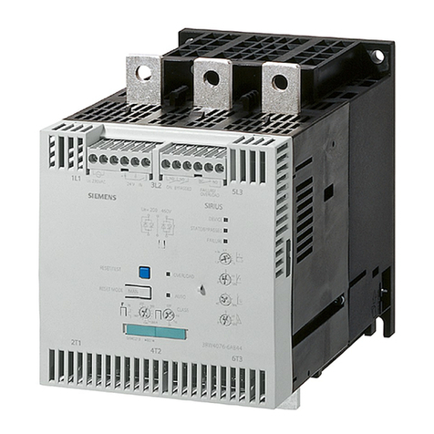
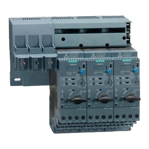
  9. Siemens 3RW51 Series User manual

Siemens 3RW51 Series User manual

Other Siemens Controllers manuals

Siemens SIMATIC S7 F User manual

Siemens

Siemens SIMATIC S7 F User manual

Siemens SQD Series User manual

Siemens

Siemens SQD Series User manual

Siemens Flowrite 599 Series Owner's manual

Siemens

Siemens Flowrite 599 Series Owner's manual

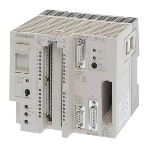
Siemens SIMATIC S5 Series User manual

Siemens

Siemens SIMATIC S5 Series User manual

Siemens SIPART DR22 User manual

Siemens

Siemens SIPART DR22 User manual

Siemens SIRIUS 3RF29-0KA Series User manual

Siemens

Siemens SIRIUS 3RF29-0KA Series User manual

Siemens ST950 User manual

Siemens

Siemens ST950 User manual

Siemens SIMATIC S7-200 User manual

Siemens

Siemens SIMATIC S7-200 User manual

Siemens Simatic S7-300 User manual

Siemens

Siemens Simatic S7-300 User manual

Siemens SIPART DR19 User manual

Siemens

Siemens SIPART DR19 User manual

Siemens FC18 Series User manual

Siemens

Siemens FC18 Series User manual

Siemens OpenAir GDE131.1U User manual

Siemens

Siemens OpenAir GDE131.1U User manual

Siemens SINAMICS G120 User manual

Siemens

Siemens SINAMICS G120 User manual

Siemens LME SERIES Operating and maintenance instructions

Siemens

Siemens LME SERIES Operating and maintenance instructions

Siemens SITRANS I100 7NG4124-0AA00 User manual

Siemens

Siemens SITRANS I100 7NG4124-0AA00 User manual

Siemens SINUMERIK 840D pl User manual

Siemens

Siemens SINUMERIK 840D pl User manual

Siemens FT2001-A1 User manual

Siemens

Siemens FT2001-A1 User manual

Siemens SIMATIC PN/BACnet LINK User manual

Siemens

Siemens SIMATIC PN/BACnet LINK User manual

Siemens SIRIUS 3SE5000-0A Series User manual

Siemens

Siemens SIRIUS 3SE5000-0A Series User manual

Siemens 5WG1 523-1AB04 User manual

Siemens

Siemens 5WG1 523-1AB04 User manual

Siemens N 562/11 User manual

Siemens

Siemens N 562/11 User manual

Siemens SIMATIC S7-1200 Instruction Manual

Siemens

Siemens SIMATIC S7-1200 Instruction Manual

Siemens OpenAir GBB Series Installation guide

Siemens

Siemens OpenAir GBB Series Installation guide

Siemens SINAMICS S120 Technical Document

Siemens

Siemens SINAMICS S120 Technical Document

Popular Controllers manuals by other brands

Sunricher SR-ZV9003T3-RGBW-US Installation

Sunricher

Sunricher SR-ZV9003T3-RGBW-US Installation

Ksenia intro Installation and configuration manual

Ksenia

Ksenia intro Installation and configuration manual

Inovance CAN200 Series manual

Inovance

Inovance CAN200 Series manual

Gauzy LC6 FLEX Controller Installation and operation guide

Gauzy

Gauzy LC6 FLEX Controller Installation and operation guide

Viking SLP-1 Technical practice

Viking

Viking SLP-1 Technical practice

CKD KBX-30E-U Series instruction manual

CKD

CKD KBX-30E-U Series instruction manual

Sharp Energy Sun Flux User manual & installation guide

Sharp Energy

Sharp Energy Sun Flux User manual & installation guide

Yamaha RCX40 user manual

Yamaha

Yamaha RCX40 user manual

AB Quality PowerFlex 400 Frames D-H Service bulletin

AB Quality

AB Quality PowerFlex 400 Frames D-H Service bulletin

Yamaha MJC8 owner's manual

Yamaha

Yamaha MJC8 owner's manual

AL-KO ATC operating instructions

AL-KO

AL-KO ATC operating instructions

Savant SmartControl 2 Deployment guide

Savant

Savant SmartControl 2 Deployment guide

GameSir T3S user manual

GameSir

GameSir T3S user manual

Kostal inveor operating manual

Kostal

Kostal inveor operating manual

Emerson Yarway 20-55 Operating and safety instructions

Emerson

Emerson Yarway 20-55 Operating and safety instructions

CoCo ACM-LV24 Quick installation guide

CoCo

CoCo ACM-LV24 Quick installation guide

Brooks SLA5810/20 Installation and operation manual

Brooks

Brooks SLA5810/20 Installation and operation manual

SIGMA TEK SR 011 Technical manual

SIGMA TEK

SIGMA TEK SR 011 Technical manual

manuals.online logo
manuals.online logoBrands
  • About & Mission
  • Contact us
  • Privacy Policy
  • Terms and Conditions

Copyright 2025 Manuals.Online. All Rights Reserved.

3RW51 Soft Starter
Industrial Controls
Soft starters and solid-state
switching devices
3RW51 Soft Starter
Manual
06/2019
A5E37108631002A/RS
-AB/002
Description
1
Safety information
2
Mounting and Dismantling
3
Wiring
4
Parameter assignment
5
Commissioning
6
Functions
7
Messages & diagnostics
8
Maintenance and servicing
9
Technical specifications
10
Dimension drawings
11
Circuit diagrams
12
Example circuits
A
Third-party software
B
Siemens AG
Smart
Infrastructure
Control Products
Postfach 2355
90713 FUERTH
GERMANY
A5E37108631002A/RS-AB/002
Ⓟ
06/2019 Subject to change
Copyright © Siemens AG 2018.
All rights reserved
Legal information
Warning notice system
This manual contains notices you have to observe in order to ensure your personal safety, as well as to prevent
damage to property. The notices referring to your personal safety are highlighted in the manual by a safety alert
symbol, notices referring only to property damage have no safety alert symbol. These notices shown below are
graded according to the degree of danger.
DANGER
indicates that death or severe personal injury will result if proper precautions are not taken.
WARNING
indicates that death or severe personal injury may result if proper precautions are not taken.
CAUTION
indicates that minor personal injury can result if proper precautions are not taken.
NOTICE
indicates that property damage can result if proper precautions are not taken.
If more than one degree of danger is present, the warning notice representing the highest degree of danger will
be used. A notice warning of injury to persons with a safety alert symbol may also include a warning relating to
property damage.
Qualified Personnel
The product/system described in this documentation may be operated only by personnel qualified for the specific
task in accordance with the relevant documentation, in particular its warning notices and safety instructions.
Qualified personnel are those who, based on their training and experience, are capable of identifying risks and
avoiding potential hazards when working with these products/systems.
Proper use of Siemens products
Note the following:
WARNING
Siemens products may only be used for the applications described in the catalog and in the relevant technical
documentation. If products and components from other manufacturers are used, these must be recommended
or approved by Siemens. Proper transport, storage, installation, assembly, commissioning, operation and
maintenance are required to ensure that the products operate safely and without any problems. The permissible
ambient conditions must be complied with. The information in the relevant documentation must be observed.
Trademarks
All names identified by ® are registered trademarks of Siemens AG. The remaining trademarks in this publication
may be trademarks whose use by third parties for their own purposes could violate the rights of the owner.
Disclaimer of Liability
We have reviewed the contents of this publication to ensure consistency with the hardware and software
described. Since variance cannot be precluded entirely, we cannot guarantee full consistency. However, the
information in this publication is reviewed regularly and any necessary corrections are included in subsequent
editions.
3RW51 Soft Starter
Manual, 06/2019, A5E37108631002A/RS-AB/002 3
Table of contents
1 Description................................................................................................................................................. 7
1.1 Target group .............................................................................................................................7
1.2 Device design ...........................................................................................................................8
1.3 Operating principle....................................................................................................................9
1.4 Interaction interfaces ..............................................................................................................11
1.5 Operating modes and master control function........................................................................12
1.6 Device versions.......................................................................................................................13
1.7 Areas of application / load types.............................................................................................14
1.8 Selection of the soft starter using the Simulation Tool for Soft Starters.................................15
1.9 Structure of the article number ...............................................................................................16
1.10 Accessories.............................................................................................................................17
1.10.1 Communication modules ........................................................................................................17
1.10.2 3RW5 HMI ..............................................................................................................................18
1.11 Additional documentation .......................................................................................................20
1.12 Siemens Industry Online Support ...........................................................................................21
1.13 Support Request.....................................................................................................................23
1.14 Siemens Industry Online Support app....................................................................................23
2 Safety information.................................................................................................................................... 25
2.1 Security information ................................................................................................................25
2.2 ESD Guidelines.......................................................................................................................26
2.3 Five safety rules for working in or on electrical systems ........................................................28
2.4 Reactive power compensation................................................................................................29
3 Mounting and Dismantling ....................................................................................................................... 31
3.1 Installing the 3RW51 soft starter.............................................................................................31
3.2 Mounting the fan cover ...........................................................................................................32
3.3 Mounting the 3RW51 soft starter on a level surface...............................................................34
3.4 Mounting the external bypass contactor.................................................................................36
3.5 Installing / mounting / removing 3RW5 HMI ...........................................................................36
3.5.1 Installing the 3RW5 HMI Standard in 3RW51 soft starter ......................................................36
3.5.2 Removing 3RW5 HMI Standard .............................................................................................38
3.5.3 Installing the 3RW5 HMI High Feature in the 3RW51 soft starter..........................................39
3.5.4 Removing 3RW5 HMI High Feature .......................................................................................40
3.5.5 Installing the 3RW5 HMI Standard in the control cabinet door...............................................41
3.5.6 Installing the 3RW5 HMI High Feature in the control cabinet door ........................................44
Table of contents
3RW51 Soft Starter
4Manual, 06/2019, A5E37108631002A/RS-AB/002
3.5.7 Installing the 3RW5 HMI Standard on a flat surface.............................................................. 47
3.5.8 Installing the 3RW5 HMI High Feature on a flat surface ....................................................... 49
3.5.9 Cut out the hinged cover for 3RW5 HMI................................................................................ 50
3.5.10 Replacing the hinged cover of the 3RW51 soft starter .......................................................... 51
4 Wiring ...................................................................................................................................................... 53
4.1 Connections ........................................................................................................................... 53
4.1.1 Overview of all connections ................................................................................................... 53
4.1.2 State diagrams of the inputs and outputs .............................................................................. 55
4.2 Connecting the 3RW51 soft starter........................................................................................ 56
4.3 Connecting 3RW51 soft starter to main circuit connection (line side / motor side) ............... 57
4.4 Connecting the external bypass contactor to the 3RW51 soft starter ................................... 59
4.5 Replacing the terminals on size 1/2 devices.......................................................................... 61
4.6 Connecting the control terminals (screw terminals)............................................................... 63
4.7 Disconnecting the control terminals from the screw-type terminals ...................................... 64
4.8 Replacing the control terminals.............................................................................................. 65
4.9 Installing the cover for the control cable duct (optional accessory) ....................................... 67
4.10 Removing the cover of the control cable duct (optional accessory) ...................................... 68
5 Parameter assignment............................................................................................................................. 69
5.1 Setting elements on the 3RW51 soft starter .......................................................................... 69
5.2 Overview of parameters......................................................................................................... 71
5.3 Suggested settings ................................................................................................................ 72
5.4 Parameterizing the 3RW51 soft starter.................................................................................. 73
5.5 Setting RESET MODE and Soft Torque ................................................................................ 74
5.6 RESET MODES ..................................................................................................................... 76
5.7 Parameterizing output 13 / 14 (Output signal ON or RUN) ................................................... 77
5.8 Analog output......................................................................................................................... 78
6 Commissioning ........................................................................................................................................ 79
6.1 Commissioning the 3RW51 soft starter ................................................................................. 79
6.2 Sealing the 3RW51 soft starter .............................................................................................. 80
6.3 First commissioning of the 3RW5 HMI High Feature............................................................. 81
7 Functions ................................................................................................................................................. 83
7.1 Soft starting ............................................................................................................................ 83
7.2 Current limiting function ......................................................................................................... 86
7.3 Soft stopping .......................................................................................................................... 88
7.4 Motor protection ..................................................................................................................... 89
7.4.1 Electronic motor overload protection ..................................................................................... 89
7.5 Intrinsic device protection ...................................................................................................... 90
Table of contents
3RW51 Soft Starter
Manual, 06/2019, A5E37108631002A/RS-AB/002 5
7.6 Soft Torque .............................................................................................................................91
7.7 Additional parameters.............................................................................................................93
7.8 3RW5 HMI Standard...............................................................................................................94
7.8.1 Design of the 3RW5 HMI Standard ........................................................................................94
7.8.2 3RW5 HMI Standard menu.....................................................................................................95
7.8.3 Setting station address via 3RW5 HMI Standard ...................................................................99
7.9 3RW5 HMI High Feature ......................................................................................................100
7.9.1 Design and operator controls of the 3RW5 HMI High Feature.............................................100
7.9.2 Main menu of the 3RW5 HMI High Feature with the 3RW51 soft starter.............................103
7.9.3 Parameterizing the 3RW5 HMI High Feature .......................................................................107
7.9.4 Monitoring .............................................................................................................................108
7.9.4.1 Monitoring the measured values of the 3RW51 soft starter with the 3RW5 HMI High
Feature..................................................................................................................................108
7.9.4.2 Monitoring the process image of the 3RW51 soft starter with the 3RW5 HMI High
Feature..................................................................................................................................109
7.9.5 Parameterizing analog output AQ via the 3RW5 HMI High Feature ....................................109
7.9.6 Overview ...............................................................................................................................111
7.9.7 Defining the local access protection (PIN)............................................................................113
7.9.8 Micro SD card .......................................................................................................................115
8 Messages & diagnostics ........................................................................................................................ 117
8.1 Diagnostics options...............................................................................................................117
8.2 LED display...........................................................................................................................117
8.2.1 Overview of the device LEDs of the 3RW51 soft starter ......................................................117
8.2.2 Status and error displays ......................................................................................................118
8.2.3 LED STATE / OVERLOAD ...................................................................................................119
8.2.4 Overview of LEDs on 3RW5 HMI Standard..........................................................................120
8.2.5 Overview of LEDs on 3RW5 HMI High Feature ...................................................................121
8.3 Warnings and remedial measures ........................................................................................122
8.4 Faults and remedial actions of the 3RW51 soft starter.........................................................123
8.5 Faults and remedial actions on the 3RW5 HMI High Feature ..............................................126
8.6 RESET MODES....................................................................................................................127
8.7 Diagnostics via the 3RW5 HMI High Feature module ..........................................................128
8.7.1 Diagnostics of the 3RW51 soft starter with the 3RW5 HMI High Feature............................128
8.7.2 Diagnostics of communication with the 3RW5 HMI High Feature........................................130
8.7.3 Execute HMI diagnostics with the 3RW5 HMI High Feature ................................................131
8.7.4 Logbooks ..............................................................................................................................132
9 Maintenance and servicing .................................................................................................................... 133
9.1 Maintenance and repairs ......................................................................................................133
9.2 User test................................................................................................................................134
9.3 Firmware update...................................................................................................................137
9.4 Perform the firmware update using micro SD memory card (3RW5 HMI High feature).......138
9.5 Restore factory setting..........................................................................................................139
9.5.1 Restoring the factory settings via 3RW5 HMI High Feature.................................................140
9.5.2 Restoring the factory settings with the reset button via 3RW5 HMI High Feature ...............141
Table of contents
3RW51 Soft Starter
6Manual, 06/2019, A5E37108631002A/RS-AB/002
10 Technical specifications......................................................................................................................... 143
10.1 Technical data in Siemens Industry Online Support............................................................ 143
11 Dimension drawings .............................................................................................................................. 145
11.1 CAx data .............................................................................................................................. 145
12 Circuit diagrams..................................................................................................................................... 147
12.1 CAx data .............................................................................................................................. 147
A Example circuits..................................................................................................................................... 149
A.1 Main circuit connection ........................................................................................................ 149
A.1.1 Feeder assembly, type of coordination 1 fuseless............................................................... 149
A.1.2 Feeder assembly, type of coordination 1 with fuses............................................................ 150
A.1.3 Feeder assembly, type of coordination 2............................................................................. 151
A.1.4 Inside-delta circuit ................................................................................................................ 152
A.2 Control circuit connection..................................................................................................... 156
A.2.1 Control by pushbutton.......................................................................................................... 156
A.2.2 Control by switch.................................................................................................................. 158
A.2.3 Switching with the control supply voltage ............................................................................ 160
A.2.4 Control by PLC..................................................................................................................... 162
A.2.5 Actuation of a line contactor................................................................................................. 165
A.2.6 Wiring for remote RESET .................................................................................................... 167
A.2.7 Connecting the evaluation unit to the analog output............................................................ 167
A.2.8 Serial starting of 3RW51 soft starter with 3 parameter sets ................................................ 168
A.3 Special applications ............................................................................................................. 170
A.3.1 Controlling a motor with a magnetic parking brake.............................................................. 170
A.3.2 EMERGENCY STOP shutdown to SIL 1 or PL c with a 3SK1 safety relay......................... 172
A.3.2.1 Wiring of the 3SK1 safety relay SIL 1 with line contactor .................................................... 175
A.3.2.2 Wiring of the 3SK1 safety relay SIL 1 without line contactor ............................................... 176
A.3.3 EMERGENCY STOP shutdown to SIL 3 or PL e with a 3SK1 safety relay ........................ 177
A.3.3.1 Wiring of the 3SK1 safety relay SIL 3 with line contactor .................................................... 180
A.3.3.2 Wiring of the 3SK1 safety relay SIL 3 with line contactor .................................................... 181
A.3.4 Contactor for emergency start ............................................................................................. 182
B Third-party software............................................................................................................................... 185
B.1 Information about third-party software ................................................................................. 185
Glossary ................................................................................................................................................ 189
Index...................................................................................................................................................... 191
3RW51 Soft Starter
Manual, 06/2019, A5E37108631002A/RS-AB/002 7
Description
1
1.1 Target group
The manual is intended for everyone involved in the following tasks:
●Planning and configuring systems
●Installation
●Commissioning
●Service and maintenance
Requirements for use of 3RW5 soft starters
Basic knowledge of the following areas:
●General electrical engineering
●Drive technology
●Automation technology
●Handling the automation system and the software used
Description
1.2 Device design
3RW51 Soft Starter
8Manual, 06/2019, A5E37108631002A/RS-AB/002
1.2 Device design
①
Main circuit connection (mains supply and external bypass)
②
Slot for 3RW5 HMI Standard or 3RW5 HMI High Feature (accessories)
③
Interface for 3RW5 HMI Standard or 3RW5 HMI High Feature (accessories)
④
Setting elements for parameter assignment
⑤
MODE key
⑥
Slot for 3RW5 communication module (accessory)
⑦
Connectable conductor cross sections
⑧
Scale for the setting element Ie
⑨
Diagnostics LEDs and RESET key
⑩
Eye for lead seal
⑪
Main circuit connection (motor)
⑫
Control terminals (inputs / outputs)
⑬
Control cable duct
Description
1.3 Operating principle
3RW51 Soft Starter
Manual, 06/2019, A5E37108631002A/RS-AB/002 9
1.3 Operating principle
Soft starters are used to start three-phase induction motors with reduced torque and reduced
starting current.
The 3RW51 soft starter starts the motor as soon as the switch-on command is issued (t1).
During the ramp-up time (t1to t3), the current is conducted via power semiconductors which
starts up the motor smoothly.
The 3RW51 soft starter features internal run-up recognition. The following operation occurs
when the motor reaches its rated operating speed before the ramp-up time expires:
●The motor voltage is immediately increased to 100 % of the line voltage (t2)
●The external bypass contactor close
●The power semiconductors are bypassed and the soft starter is in bypass operation.
Coast-down to zero speed is activated when the switch-on command is cancelled (t4) and
the motor is shut down. The power semiconductors also ensure that the motor coasts down
smoothly to a stop. The power supply to the motor is maintained (t5) until the end of the
ramp-down time is reached (t4to t5). It may take longer for the motor to actually coast down
to a standstill (t6).
①
Speed
t5
End of the set ramp-down time (t5-t4)
②
Voltage
t6
Motor at standstill
t1
Motor start-up with set starting voltage US
US
Set starting voltage
t2
Rated speed ne achieved
Ue
Rated operational voltage
t3
End of the set ramp-up time (t3-t1)
ne
Rated motor speed
t4Switch-on command is cancelled, motor is
switched off
Description
1.3 Operating principle
3RW51 Soft Starter
10 Manual, 06/2019, A5E37108631002A/RS-AB/002
Functions
●Soft starting with parameterizable starting voltage and starting ramp time
●Soft stopping with parameterizable ramp-down time
●Parameterizable current limiting function
●Soft torque for smooth ramp-up and ramp-down (avoiding torque peaks by means of
torque limitation)
●Integrated motor overload protection with adjustable trip class (Class 10A, 10E, 20E,
Class OFF)
●The intrinsic device protection protects the 3RW51 soft starter against overload
●Ramp-up detection
●Extended operating and diagnostic functions is provided by the optional 3RW5 HMI
Standard or 3RW5 HMI High Feature
●Connection to motor in inline circuit or inside-delta circuit
●Adjustable RESET MODE (manual RESET, remote RESET, auto RESET) for the
functions of motor protection
●Analog output for output of a measured value
●Optional 3RW5 communication module for integration into bus systems
●Firmware updates upgrade the firmware of the respective device
Further details can be found in Chapter Functions (Page 83).