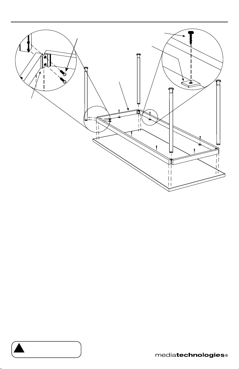
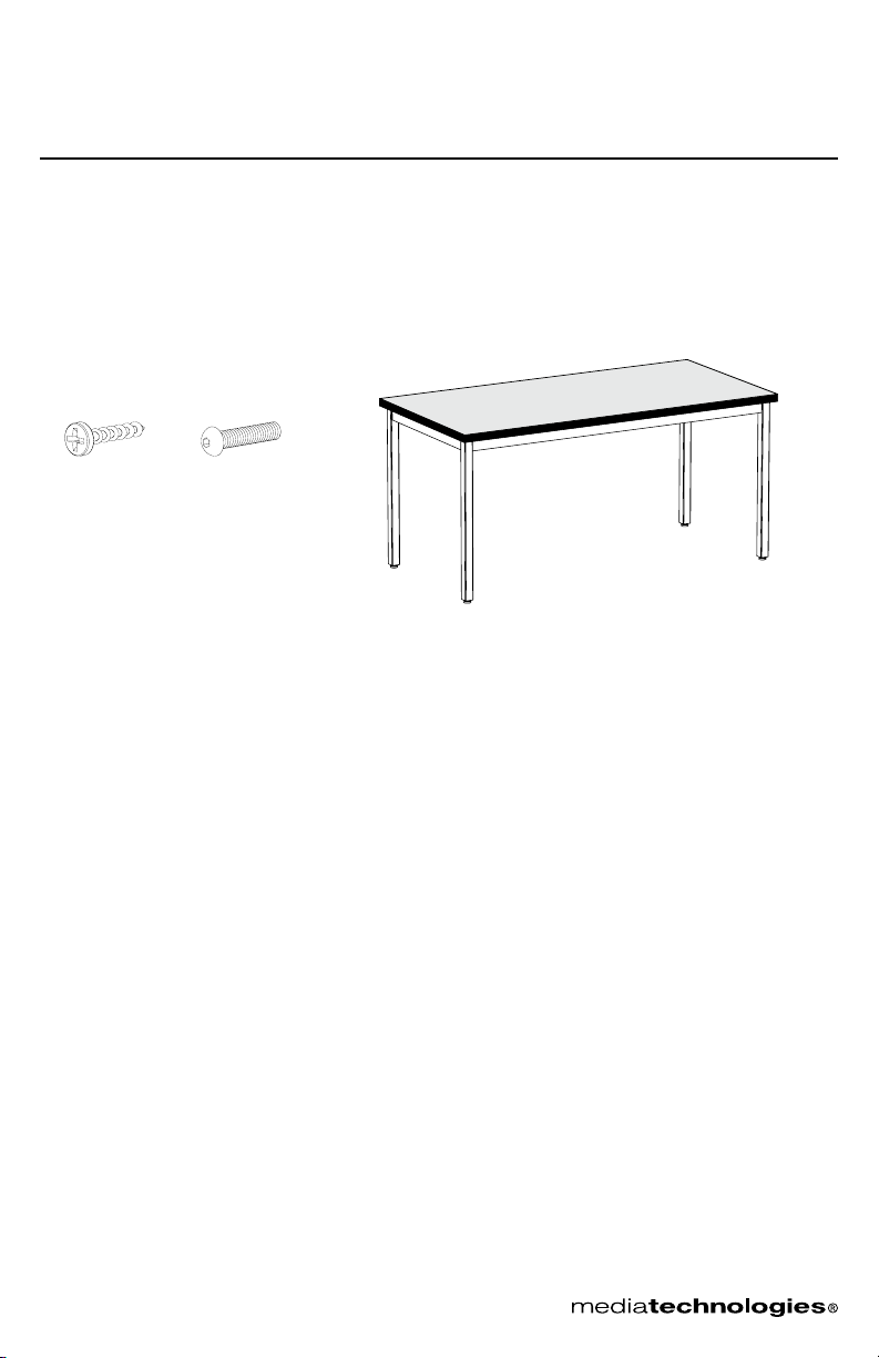
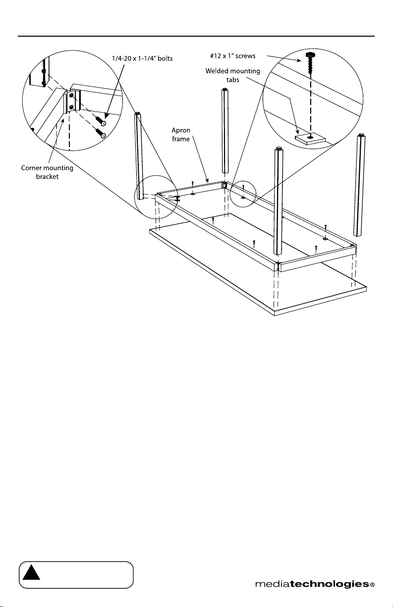
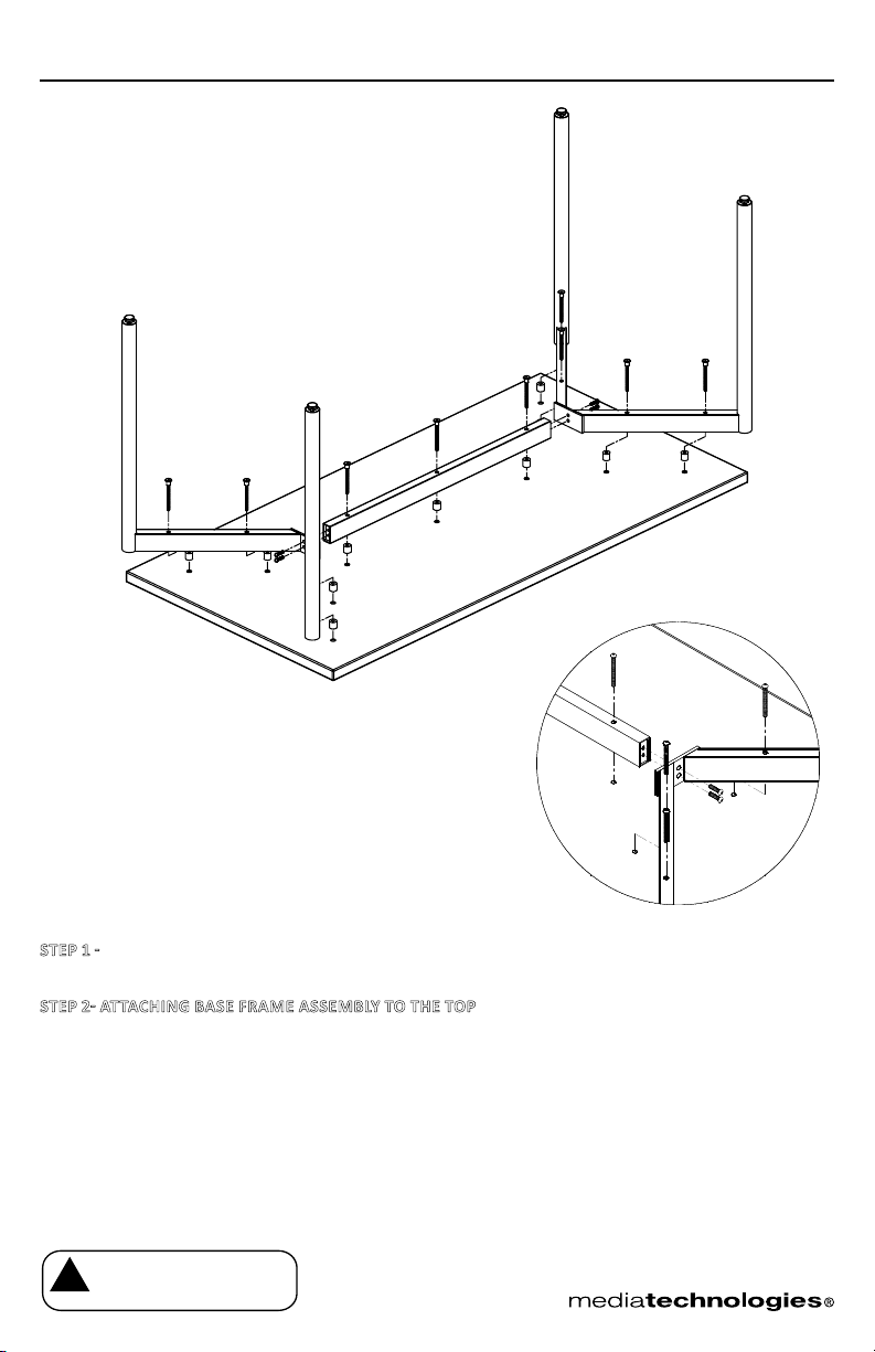
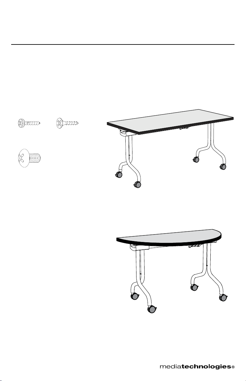
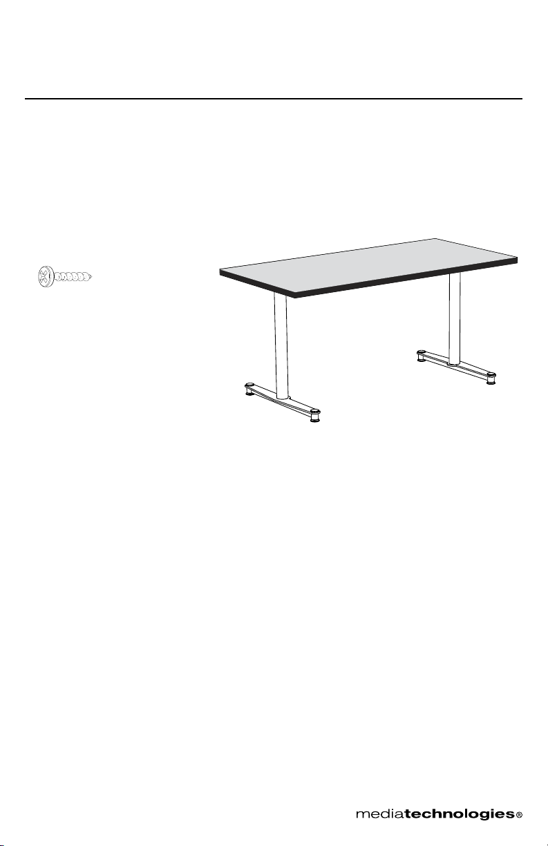
Media Technologies Cirrus Guide

Cirrus • Eclipse • GTX • Jill • Matrix • Milestone • OTZ • Quest
Radius • Rockford • SST • Technix • Titan • Trix • Vector • Vortex
WCT • Z Tables
TABLES
www.mediatechnologies.com
Installaon and Assembly
Instrucon Guide


3
Assemble tables only as described in this
guide. All fasteners must be tightened
securely and checked regularly. Failure to
do so could cause instability and injury.
!
CAUTION
Table of Contents
Radius................................................................................... 4
Cirrus .................................................................................... 6
Quest .................................................................................... 8
Trix...................................................................................... 10
Vortex ................................................................................. 12
SST ...................................................................................... 14
Vector ................................................................................. 16
Technix................................................................................ 18
Eclipse................................................................................. 20
GTX ..................................................................................... 22
OTZ ..................................................................................... 24
Milestone ........................................................................... 26
WCT .................................................................................... 28
Z Table ................................................................................ 32
Rockford ............................................................................. 34
Titan ................................................................................... 36
Jack..................................................................................... 38
Jill........................................................................................ 40
Matrix Modular Workstaons ............................................ 42

4
Radius
Steel Modesty Panel
Veneer Modesty Panel
#12 x 1" screws
Machine Screw
10-32 x 5/8"
#8 x 1" screws
Steel Modesty Panel:
Cam Studs
Veneer Modesty Panel:
Tools Required:
#2 Phillips Head Screwdriver
#3 Phillips Head Screwdriver
Hardware Included:
Cam Studs 15 Cam

5
Assemble tables only as described in this
guide. All fasteners must be tightened
securely and checked regularly. Failure to
do so could cause instability and injury.
!
CAUTION
Radius
FOR STEEL MODESTY PANEL:
STEP 1: ATTACH MODESTY TO LEGS
Posion the modesty panel between the leg
frames with wire trough facing front of the table.
Aach to the leg frames using (4) M6 x
10mm Bolts.
STEP 2: ATTACHING THE LEG FRAME ASSEM
BLY TO THE TABLE TOP
Place the top upside down on a clean padded
surface. Locate the steel leg frame assembly on to
the table top above the machined locaons. At-
tach legs to the top using (6) #12 x 1" PH Screws
per leg. Fasten the modesty panel to the top
using #8 x 1" PH Screws.
Verify all bolts/ screws are ghtened.
FOR VENEER MODESTY PANEL:
STEP 1: ATTACH MODESTY TO LEGS
Install (2) cams into pre-drilled holes on each end
of the modesty panel. Screw the threaded end of
(2) 15mm Cams into each steel leg. Slide modesty
panel onto the cam studs and turn the cams to
secure the panel to the legs.
STEP 2: ATTACHING THE LEG FRAME ASSEM
BLY TO THE TABLE TOP
Place the top upside down on a clean padded
surface. Locate the steel leg frame assembly on to
the table top above the machined locaons. At-
tach legs to the top using (6) #12 x 1" PH Screws
per leg.
Verify all bolts/ screws are ghtened.
Steel Modesty Panel Veneer Modesty Panel
Steel Modesty Panel Veneer Modesty Panel Leg Frame and Table Top

6
Cirrus
Steel Modesty Panel
Veneer Modesty Panel
Tools Required:
#2 Phillips Head Screwdriver
#3 Phillips Head Screwdriver
#12 x 1" screws
Hardware Included:
machine screws
10-32 x 5/8"
#8 x 1" screws
Steel Modesty Panel:
15mm cam cam studs
Veneer Modesty Panel:

7
Assemble tables only as described in this
guide. All fasteners must be tightened
securely and checked regularly. Failure to
do so could cause instability and injury.
!
CAUTION
Cirrus
FOR STEEL MODESTY PANEL:
STEP 1: ATTACH MODESTY TO LEGS
Posion the modesty panel between the leg
frames with wire trough facing front of the table.
Aach to the leg frames using (4) M6 x
10mm Bolts.
STEP 2: ATTACHING THE LEG FRAME ASSEM
BLY TO THE TABLE TOP
Place the top upside down on a clean padded
surface. Locate the steel leg frame assembly on to
the table top above the machined locaons. At-
tach legs to the top using (6) #12 x 1" PH Screws
per leg. Fasten the modesty panel to the top
using #8 x 1" PH Screws.
Verify all bolts/ screws are ghtened.
FOR VENEER MODESTY PANEL:
STEP 1: ATTACH MODESTY TO LEGS
Install (2) cams into pre-drilled holes on each end
of the modesty panel. Screw the threaded end of
(2) 15mm Cams into each steel leg. Slide modesty
panel onto the cam studs and turn the cams to
secure the panel to the legs.
STEP 2: ATTACHING THE LEG FRAME ASSEM
BLY TO THE TABLE TOP
Place the top upside down on a clean padded
surface. Locate the steel leg frame assembly on to
the table top above the machined locaons. At-
tach legs to the top using (6) #12 x 1" PH Screws
per leg.
Verify all bolts/ screws are ghtened.
Steel Modesty Panel Veneer Modesty Panel
Steel Modesty Panel Veneer Modesty PanelLeg Frame and Table Top

8
Quest
Steel Modesty Panel
Veneer Modesty Panel
#12 x 1" screws
Hardware Included:
machine screws
10-32 x 5/8"
#8 x 1" screws
Steel Modesty Panel:
15mm cam
inserts
15mm cam studs
Veneer Modesty Panel:
Tools Required:
#2 Phillips Head Screwdriver
#3 Phillips Head Screwdriver

9
Assemble tables only as described in this
guide. All fasteners must be tightened
securely and checked regularly. Failure to
do so could cause instability and injury.
!
CAUTION
Quest
FOR STEEL MODESTY PANEL:
STEP 1: ATTACH MODESTY TO LEGS
Posion the modesty panel between the leg
frames with wire trough facing front of the table.
Aach to the leg frames using (4) M6 x
10mm Bolts.
STEP 2: ATTACHING THE LEG FRAME ASSEM
BLY TO THE TABLE TOP
Place the top upside down on a clean padded
surface. Locate the steel leg frame assembly on to
the table top above the machined locaons. At-
tach legs to the top using (6) #12 x 1" PH Screws
per leg. Fasten the modesty panel to the top
using #8 x 1" PH Screws.
Verify all bolts/ screws are ghtened.
FOR VEENEER MODESTY PANEL:
STEP 1: ATTACH MODESTY TO LEGS
Install (2) cams into pre-drilled holes on each end
of the modesty panel. Screw the threaded end of
(2) 15mm Cams into each steel leg. Slide modesty
panel onto the cam studs and turn the cams to
secure the panel to the legs.
STEP 2: ATTACHING THE LEG FRAME ASSEM
BLY TO THE TABLE TOP
Place the top upside down on a clean padded
surface. Locate the steel leg frame assembly on to
the table top above the machined locaons. At-
tach legs to the top using (6) #12 x 1" PH Screws
per leg.
Verify all bolts/ screws are ghtened.
Steel Modesty Panel Veneer Modesty Panel
Steel Modesty Panel Veneer Modesty Panel Leg Frame and Table Top

10
Trix
10mm M6 bolts
Tools Required:
#3 Phillips Head Screwdriver
10 mm Wrench
#12 x 1" screws
Hardware Included:
Steel Modesty Panel:

11
Assemble tables only as described in this
guide. All fasteners must be tightened
securely and checked regularly. Failure to
do so could cause instability and injury.
!
CAUTION
Trix
STEP 1: ATTACH LEG ASSEMBLY TO UNDERSIDE OF TOP
Line up leg plate with locang holes on underside of top. Aach leg assembly to underside of top using
#12 x 1" PH Screws (do not over ghten).
STEP 2: ATTACHING OPTIONAL CURVED MODESTY PANEL
Fasten curved bracket to curved modesty with M6 x 10mm Bolts into threaded insert. Aach curved modesty
assembly to underside of Top with M6 x 10mm into threaded inserts again.
Verify all bolts/screws are ghtened.
Keel required for tables 60" +.
Center keel along midline and equal distance from each end. Aach using
#12 x 1" screws.
Legs come assembled.
Trix table with keel
Trix table with keel and
veneer modesty panel

12
Tools Required:
#3 Phillips Head Screwdriver
5/32" Allen wrench
Vortex
#12 x 1" screws 1/4-20 x 1-1/4"
bolts
Hardware Included:

13
Assemble tables only as described in this
guide. All fasteners must be tightened
securely and checked regularly. Failure to
do so could cause instability and injury.
!
CAUTION
Vortex
STEP 1: ATTACHING THE LEGS TO THE APRON FRAME
Aach each leg by bolng through a corner mounng bracket into welded threaded insert in leg using
(2) 1/4-20 x 1-1/4 bolts per leg.
STEP 2: ATTACHING THE FRAME ASSEMBLY TO THE TABLE TOP
Place the table top upside down on a clean, padded surface. Center the frame assembly onto the underside of
the table top. Secure frame assembly to the table top through the welded mounng tabs using
#12 x 1" screws.
#12 x 1" screws
Welded mounting
tabs
1/4-20 x 1-1/4" bolts
Corner mounting
bracket
Apron
frame

14
SST
Tools Required:
#3 Phillips Head Screwdriver
5/32" Allen wrench
#12 x 1" screws 1/4-20 x 1-1/4"
bolts
Hardware Included:

15
Assemble tables only as described in this
guide. All fasteners must be tightened
securely and checked regularly. Failure to
do so could cause instability and injury.
!
CAUTION
SST
STEP 1: ATTACHING THE LEGS TO THE APRON
Aach each leg by bolng through a corner mounng bracket into welded threaded insert in leg using
(2) 1/4-20 x 1-1/4 bolts per leg. Note: For epoxy tops, skip to Step 4.
STEP 2: ATTACHING THE FRAME ASSEMBLY TO THE TABLE TOP
Place the table top upside down on a clean, padded surface. Center the length and width of welded apron
from on underside of top. Drill 5/32" pilot hole into top through welded mounng tabs.
STEP 3: ATTACHING APRON FRAME TO TABLE TOP
Secure apron frame to table top with #12 x 1" screws through welded mounng tabs.
STEP 4: ATTACHING EPOXY TOPS
Liquid Nails® (construcve adhesive) will be used to aache epoxy tops frame.
Place top upside down on clean, padded surface. Apply Liquid Nail® to apron frame per their instrucons.
Center length and width of apron frame onto underside of table top. Scrape o any excess liquid nails while
sll so.
Visit www.liquidnails.com for more informaon.

16
Vector
Standard, Vector Wave & Floating Top
1/4-20 x 2-1/2"
bolts
1/4 - 20 x
90 mm bolts
Tools Required:
5/32 Allen Wrench
1/4 -20 x 1
Buon Head
Hardware Included:
Standard Tops:
Floating Tops:
3/4" spacer

17
Assemble tables only as described in this
guide. All fasteners must be tightened
securely and checked regularly. Failure to
do so could cause instability and injury.
!
CAUTION
Vector
ASSEMBLE LEG FRAME TO SPANNER
Align holes in plate on end of the spanner with the holes in leg frame as shown. Secure with ¼-20 x 1” BH Bolt.
Place the table top upside down on a clean, padded surface. Align holes in base frame assembly with inserts in
underside of table top. Aach base with ¼-20 x 2-1/2” BH Bolts. Install Levelers.
ATTACHING BASE FRAME ASSEMBLY TO FLOATING TOP
Place the table top upside down on a clean, padded surface. Align holes in base frame assembly with inserts in
underside of table top and place spacers in between. Aach base thru spacers with ¼-20 x 90mm Bolts.
Install Levelers.
Verify all bolts/screws are ghtened.

18
Hardware Included:
Tools Required:
#2 Phillips Head Screwdriver
#3 Phillips Head Screwdriver
1/4-20 x 1/2"
Machine Screw
#6 x 1/2"
Flat Head Screw
#12 x 1
Pan Head Screw
Technix
Full Frame & Section Frame

19
Assemble tables only as described in this
guide. All fasteners must be tightened
securely and checked regularly. Failure to
do so could cause instability and injury.
!
CAUTION
Technix
STEP 1:
Place the top upside down on a clean, padded surface. Align holes on mounng plates with pre-drilled holes
on boom side of worksurface. Fasten each mounng plate using the (4) corner holes with #12 x 1" Phillips
Pan Head Screws. Aach the legs to the ip mechanism with ¼-20 x ½" Machine Screws.
STEP 2:
Align holes on handle base with pre-drilled holes on boom side of worksurface. Fasten handle base to
worksurface with (4) #12 x 1” Phillips Pan Head Screws.
STEP 3:
Posion cable clips evenly along the cable and fasten to boom side of worksurface with #6 x ½" Phillips Pan
Head Screws. Use handle assembly to release the mechanism and lock the aluminum beam in the upright
posion.
CRITICAL STEP:
Complete installaon of the system by fastening each mounng plate to worksurface using the four interior
holes with #12 x 1” Phillips Pan Head screws. Use handle assembly to release the mechanism and return the
beam to lowered posion.
Verify all bolts/screws are ghtened.

20
Tools Required:
#3 Phillips Screwdriver
Hardware Included:
Eclipse
#12 x 1" screws
This manual suits for next models
17
Table of contents
Other Media Technologies Indoor Furnishing manuals
Popular Indoor Furnishing manuals by other brands

MARCKERIC
MARCKERIC NIX 12703 Assembly instructions

Lightolier
Lightolier SPECPLUS SPS2GFSVA232 specification

LEXMAN
LEXMAN 3276007329735 Assembly, Use, Maintenance Manual

Greemotion
Greemotion GM-1022-2PK Assembly

Costway
Costway HW66113 user manual

OSP Designs
OSP Designs QUINTON QTN299 Assembly instructions

Whittier Wood Furniture
Whittier Wood Furniture Addison 1239DUETd Assembly instructions

Manhattan Comfort
Manhattan Comfort FORTRESS GARAGE TABLE 6GMC ASSEMBLY HANDBOOK

Amisco
Amisco 50565 Assembly instructions

Morata
Morata 7074 Assembly instructions

MARCKERIC
MARCKERIC COMODA 3C Assembly instructions

Emmezeta
Emmezeta JOHN 08 Assembly instructions