Medical Solutions TEMP 3 7000 Series User manual

5595.A
TEMP 3
FLUID WARMER
OPERATORS MANUAL
7000 Series
Medical Solutions, Inc.
3901 Centerview Drive, Suite L
Chantilly, VA 20151
800-435-7600
703-834-0039 (Fax)
www.warmiv.com

5595.A
2
TEMP 3FLUID WARMER
Read and understand the Operators Manual before using the TEMP 3Fluid Warmer.
Intended Use
The TEMP 3Fluid Warmer is designed to store, rapidly warm, and maintain the
temperature of I.V. and irrigation fluid bags prior to their use.
The TEMP 3is designed to supply warmed I.V. and irrigation fluid bags for a single
room, (i.e., Operating, LDR, Patient's, etc.). It is not intended to supply warmed I.V.
bags or irrigation solution bags to more than one room at a time.
It is suggested that each facility should contact the fluid manufacturer to obtain the
manufacturer’s specifications for time and temperature for the fluids being
warmed.
Unit Description
The TEMP 3holds up to (6) 1000ml or (6) 500 ml bags and can be attached to the wall,
a K740 stand, or an anesthesia cart. A temperature controller is used to regulate the
heating of the fluid bags and the over-temperature safety. The top display number (in
red) will indicate the temperature of the bag currently being warmed while the bottom
display number (in green) displays the desired set-point temperature. During the time
that the controller is directing the unit to warm, a light will illuminate in the upper left
corner of the display.
The Documentor®is designed to assist in the compliance with JCAHOstandard MM
2.20 and the I.V. bag manufacturer’s specifications for time and temperature.
Important Labels and Warnings:
Model/Serial Number label
Caution: Replace fuses as marked.
Caution: Electric shock hazard, do not remove protective panel. Refer servicing to Qualified
Personnel.
Caution: Verify temperature of warmed items before use.
Danger: Risk of explosion if used in the presence of flammable anesthetics.
Warning: Unit not intended for blood or blood products.
Caution: Minimum number of bags required for proper operation:
500ml - 3
1000ml - 2
Caution: Use approved cord only.

5595.A
3
Specifications
Classification Class 2
Dimensions 21.335" tall x 17.163" wide x 6.239” deep
Capacity 882 cubic inches
Mounting: Bracket for Wall Provided
MSI – K740 Stand
Construction Powder Coat Finish Aluminum
Temperature Control Specifications
Temperature Setting Range Ambient to 43C
Factory Preset Temperature 40°C
Ambient Operating Conditions
Storage Temperature -40 to +80C (-40 to 176F)
Humidity Conditions 0 to 90% up to 40C non-condensing
Operating Temperature -10 to +55C (+14 to 131F)
Atmospheric Pressure during minimum of 16.288 in. Hg
Transporting
Electrical Requirements
Power requirements 110 / 120 VAC, 60 HZ
Fused 2 each 2 amp
Amperage consumed 1.25 amps
Heater wattage 100 watts
Thermal cutout temperature 1°C over set-point temperature
5595.A
4
Set-up Instructions
1. Remove the TEMP 3from the box; leave the black foam inserts inside the cabinet. The
cabinet is setup with the foam inserts for Baxter 1000ml fluid bags.
2. Locate The Documentor®and remove from the shipping box. Attach The Documentor®to
the TEMP 3following the instructions below.
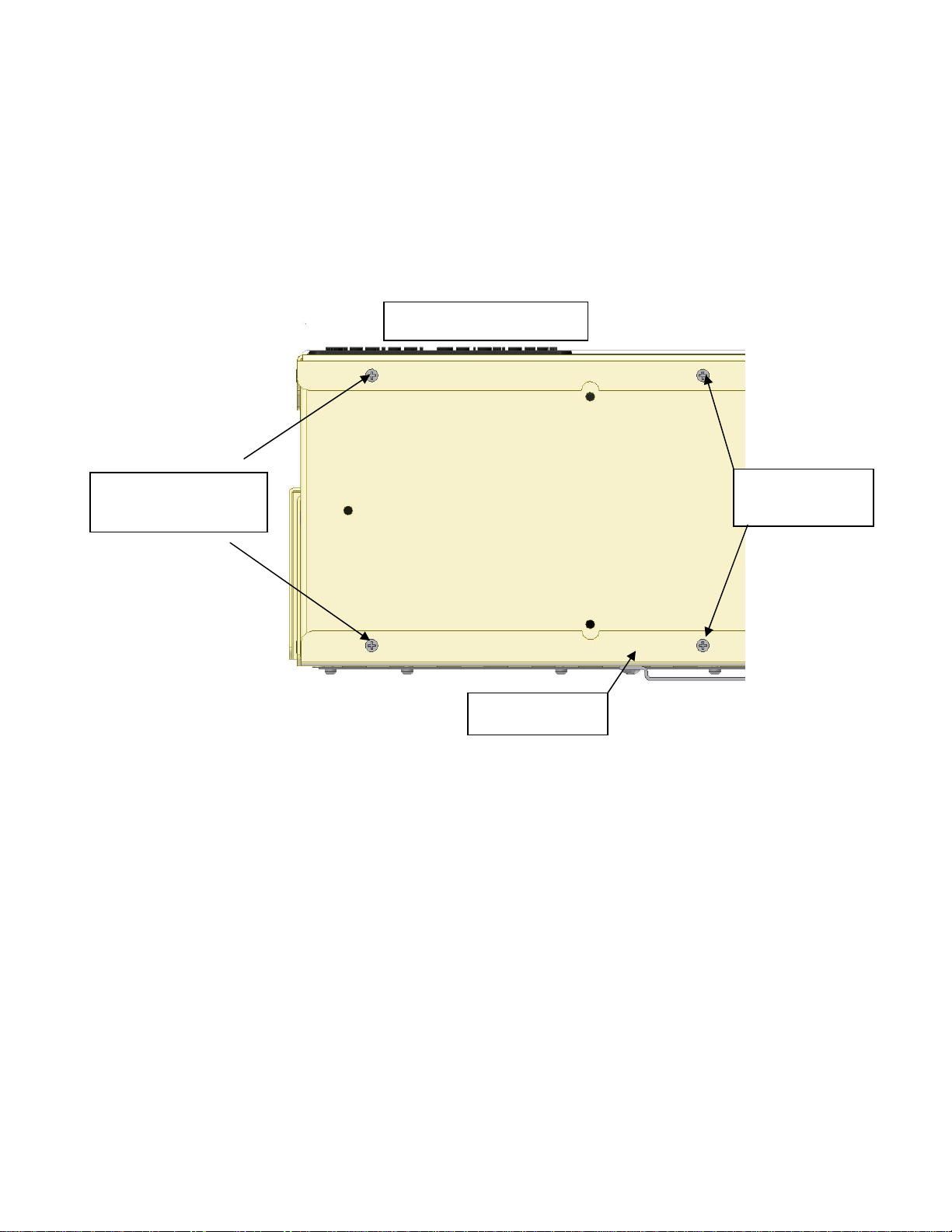
Place the TEMP 3on its back and remove the two indicated screws.
Align the holes in the TEMP 3Time/Clock Mounting Bracket to the empty screw
holes. Secure the mounting bracket using the screws removed in step one.
Remove the 3 screws in the back of The Documentor®. Attach The Documentor®to
Time/Clock Mounting Bracket using these 3 screws.
3. Locate the wall mounting bracket.
4. Mount the bracket securely in a convenient place – on a wall or cart. The TEMP 3loaded
with 6 bags of solution will weigh approximately 30 pounds. When mounting to a wall, care
should be taken to secure the bracket using suitable bolts for the wall material to support a
minimum of 90 lbs.
5. Move the TEMP 3to the desired location, check that the power switch is “off” and plug the
power cord into an approved outlet. Turn the unit on.
6. Using the key switch on the front of the cabinet unlock the doors. Load the labeled bags of
solution into the cabinet through the top door and close the door. The door locks will
automatically lock in approximately 15 seconds. If the door locks prior to closing the door,
unlock the door using the key switch and then close the door again.
Do not remove
these screws.
Front of the TEMP 3
Remove these two
screws
Back Panel

5595.A
5
The Documentor®Instructions
Prior to loading the cabinet with I.V. bags, use The Documentor®to label the I.V. bags with a
future date that follows the manufacturer’s recommendation for the length of time a bag is to
be warmed.
“Future Date Label”
To create a future date label (See The Documentor®Resetting Instructions for adjusting the clock
date):
i) Hold the Label sheet face up;
ii) Line up the arrow on The Documentor®under the words “Remove Fluid By:” on the
label;
iii) Push the label sheet towards the arrow until The Documentor®is activated; and
iv) Place a label on each I.V. bag for documentation and compliance purposes.
Load the labeled bags of solution into the TEMP 3through the top door.
Operating Instructions
1. Load the labeled bags of solution into the cabinet through the top of the cabinet.
2. Turn the unit “on” by depressing the power switch. The switch will illuminate when
energized. The controller will perform a self-test and then it will display the current
temperature of the bottom bag. The factory temperature setting is 40 degrees C. To change
the temperature setting, follow the instructions below.
3. The controller will display 2 temperatures in its display. The top display number (in red)
will indicate the current temperature of the bottom bag in the cabinet. The bottom display
number (in green) will indicate the set–point temperature (40C). During the time that the
controller is directing the unit to warm a light will illuminate in the upper left corner of the
display.
4. To change the temperature setting, follow the instructions below.
TO CHANGE THE SET POINT
i) Press the index key (left most key) to view set-point one (sp1);
ii) press the up or down arrow keys to change the set point;
iii) press the enter key (right most key) to accept the new set point; and
iv) press the index key

5595.A
6
NOTES
The TEMP 3may be left on continually without harm to the unit. It is suggested that each
facility should contact the fluid manufacturer to obtain the manufacturer’s specifications for time
and temperature for the fluids being warmed.
The TEMP 3is not intended for Blood or Blood Products.
In the event that fluid should spill inside the cabinet – unplug the unit to prevent an
electrical shock hazard and refer to step #4 of the Cleaning instructions.
The Documentor®Resetting Instructions
TO CHANGE THE DATE:
1. Plug The Documentor®into an electrical outlet.
2. Press and hold blue RESET button located on the bottom of the The Documentor®.
3. While holding down the RESET button, press and hold the •right button on the front panel.
4. While holding the •right button, release the RESET button.
5. When “Prog” appears in the display, release the •right button, Prog finishes.
6. Tap the •right button again. The display will show “0000” and the 1st digit will flash.
7. Tap the left button until the number “8” appears, then Tap the •right button twice so the third
“0” is flashing.
8. Tap the left button until the number “8” appears in the third position then Tap the
•right button.
9. Tap the left button until the number “8” appears in the fourth position. When the display reads
“8088”, Tap the •right button.
10. When the display flashes all four digits, Tap the •right button.
11. The display flashes “P1(date)”.
12. Tap the •right button and the small digits on the left, representing the year, will flash.
13. Tap the left button until the desired number appears and then Tap the •right button. The digits
representing the month should flash.
14. Tap the left button until the desired number appears and then Tap the •right button. The digits
representing the day should flash.
15. Tap the left button until the desired number appears and then Tap the •right button.
16. When the desired date is set, Tap the •right button until the display flashes “P1 (date)”.
17. Tap the blue RESET button to return to the standard display.
TO CHANGE THE TIME:
18. Follow steps 1-11.
19. Tap the left button. When the display flashes “P2 cloc”, Tap the •right button.
20. The hour format will flash (12 or 24). If necessary, tap the left button until 24 flashes. Tap the
•right button.
21. The hour digits will flash. Tap the left button until the desired setting is achieved. (the hour
must be set in military time 3:05 pm = 15:05) Tap the •right button
22. The minutes digits will flash. Tap the left button until the desired setting is achieved. Tap the
•right button twice.
23. The display will flash “P2 Cloc”, Press and release the blue RESET button.

5595.A
7
Cleaning Instructions
1. Turn the unit off and disconnect it from the power source.
2. Wipe down the cabinet with a damp cloth using a general hospital cleaner (Isopropyl
Alcohol) as needed, following the manufacturer’s instructions for the cleaner.
3. Avoid contact with the electrical connections and the electrical components.
4. In the event that excessive fluid enters the cabinet, disconnect power to the unit and refer to
qualified service personnel. Have a qualified person remove all liquid and dry the
components. Perform any necessary hospital electrical safety checks before returning the
unit to service.
Trouble Shooting
1. If the unit fails to warm, do the following:
a. Check to see that the unit is plugged in and the power switch is on.
b. Check the set-point temperature setting so that the controller is directing the unit to
warm.
c. Check to see that the minimum number of I.V. bags is loaded in the cabinet.
2. If the unit overheats call Medical Solutions, Inc.
3. Contact Medical Solutions, Inc., for any additional technical assistance @ 800-435-7600.

5595.A
8
Preventive Maintenance Plan
The TEMP 3temperature controller should be verified at least once every five years. Use of
the following items to accurately measure the bag temperature for verification.
Fluke 51II Digital Thermometer
6” Long .093” Diameter Type T Needle Thermocouple
(with the Thermocouple calibrated to the Thermometer)
With the outer wrap still on a 1000ml solution bag, pierce the bag through the needle injection
port on the bag with an 18ga needle to make it easier to insert the Thermocouple. Insert the
Thermocouple through the pierced needle injection port. Place the bag into the TEMP 3
through the lower door of the cabinet. Feed the Thermocouple wire out of the cabinet to the
Fluke Thermometer and position the probe in the center of the bag. Close the lower door. Add
five additional bags to the cabinet from the top loading door.
Turn the power to the TEMP 3on. Adjust the temperature controller set-point temperature to
40C. Allow the unit to operate for a minimum of 1 hour before verifying the temperatures.
After the allotted time, compare the temperature on the controller to the temperature reading on
the Fluke Thermometer. The two temperatures should be within one degree Celsius of each
other. If the two temperature readings are within one degree Celsius of each other the
temperature controller has been verified. If they are not, please contact Medical Solutions, Inc.
at 800-435-7600.
If a Fluke Digital Thermometer is not available a glass laboratory thermometer may be used as
an alternative. Load the unit with (6) 1000ml bags and turn the power on. Adjust the
temperature controller set-point temperature to 40C. Allow the unit to operate for a minimum
of 1 hour before verifying the temperatures. Remove the bottom bag and place the end of the
glass thermometer on top of and in the middle of the bag. Fold the bag over the thermometer and
hold for approximately two minutes or until the thermometer stops moving. If the reading on the
thermometer is between 38C and 41C the temperature controller has been verified. If it is not,
please contact Medical Solutions, Inc., at 800-435-7600.
5595.A
9
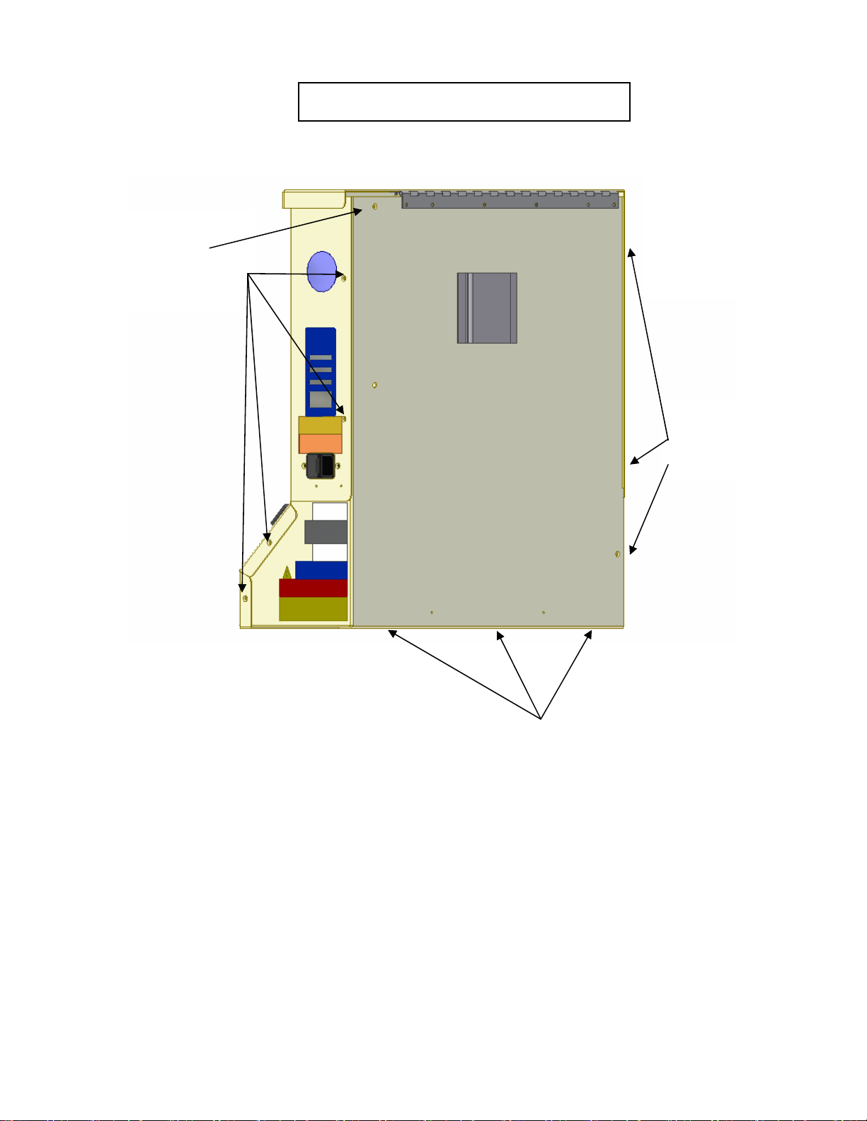
Remove the rear and
partial side panel to
access the electrical
compartment.
Remove 3 screws,
2 on the side and
1 on the back.
Remove 5 screws,
1 on the back
and 4 on the side.
Remove 3 screws on the bottom
Service panel location and removal

5595.A
10
Fuse removal instructions:
To replace the fuses, disconnect the
power cord from the unit. Use a flat
screwdriver to unlock the fuse
holder from the Power Inlet.
Replace the fuses as marked.

5595.A
11
LIMITED WARRANTY
For one year from the date of shipment to the Buyer (the “Warranty Period”), MSI warrants that the Equipment
provided to the Buyer shall be free from defects in workmanship and material. In the event of a breach of this
warranty during the Warranty Period, MSI shall, at its option, repair or replace the Equipment, and Buyer’s remedies
are limited to such repair or replacement. MSI DISCLAIMS ALL OTHER WARRANTIES, EXPRESSED OR
IMPLIED, INCLUDING THE WARRANTIES OF MERCHANTABILITY OR FITNESS FOR A PARTICULAR
PURPOSE. IN NO EVENT SHALL MSI BE LIABLE FOR DIRECT, INDIRECT, PUNITIVE, ECONOMIC,
CONSEQUENTIAL OR OTHER DAMAGES, INCLUDING BUT NOT LIMITED TO LOST PROFITS.
To enable MSI to administer the Warranty properly, Buyer shall (1) register the Warranty using the form provided
below, and (2) promptly notify MSI of any claim hereunder. As a condition to the Warranty, Buyer shall use and
maintain the Equipment according to the provisions of the Operator’s service manual.
IMPORTANT: THIS IS YOUR TEMP 3 ™ WARRANTY REGISTRATION
Please register your warranty by filling out this page and send it to Medical
Solutions, Inc., within 30 days of purchase.
A. Hospital Name:
B. Mailing Address:
C. City: State: Zip Code:
D. Contact Name:
E. Date Purchased:
F. Serial Number:
G. Department Purchased For:
COPY THIS PAGE AND MAIL TO:
Medical Solutions, Inc.
3901 Centerview Drive, Suite L
Chantilly, Virginia 20151
Fax number 703-834-0039
Table of contents
Other Medical Solutions Medical Equipment manuals


Popular Medical Equipment manuals by other brands


SYMBYX
SYMBYX BIOME DuoCare 904 quick start guide

Richmar
Richmar TheraTouch EX4 Operation manual

Sota
Sota BT6pro manual

Guilin Woodpecker Medical Instrument
Guilin Woodpecker Medical Instrument DTE Dpex I instruction manual

STARmed
STARmed VIVA combo RF Generator user guide

Chattanooga Group
Chattanooga Group Vectra Genisys 2758 user manual