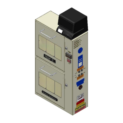
Medical Solutions 16N1 User manual

5695.B
09/04/08
16N1®
THE 1-LITER BAG WARMING SYSTEM
OPERATORS MANUAL
Medical Solutions, Inc.
3901 Centerview Drive, Suite L, Chantilly, VA 20151
(800) 435-7600 Phone • (703) 834-0039 Fax • www.warmiv.com

5695.B
i
TABLE OF CONTENTS
1.0 Intended Use ......................................................................................................... 1
2.0 System Description ............................................................................................... 1
2.1 Important Labels and Directions.............................................................................................1
3.0 General Operating Instructions ............................................................................2
3.1 Cleaning Instructions.................................................................................................................4
4.0 Specifications and Operating Information ...........................................................5
4.1 Specifications ..............................................................................................................................5
4.2 Ambient Operating Conditions................................................................................................5
4.3 Electrical Requirements.............................................................................................................5
5.0 Set-up Instructions ................................................................................................6
5.1 The Documentor®Resetting Instructions..............................................................................7
5.1.1 Changing The Documentor®Date.......................................................................................7
5.1.2 Changing The Documentor®Time ......................................................................................8
5.2 Code Lock Instructions.............................................................................................................9
5.2.1 Changing the Code Lock Sub-Master Code........................................................................9
5.2.2 Setting the Code Lock User Code ........................................................................................9
5.2.2.1 To Set Or Change the User Code Using the Sub-Master Code....................................9
5.2.2.2 To Change the User Code Using the Current User Code: ..........................................10
6.0 Troubleshooting ...................................................................................................11
6.1 Failure to Warm........................................................................................................................11

5695.B
ii
6.2 Excessive Fluids In 16N1®.....................................................................................................12
6.3 “Reload” Displayed with Fluid Bag In Compartment........................................................12
6.4 Time and Temperature Displayed for Compartment With No Bag Inserted.................12
6.5 Set Point Can Not Be Changed..............................................................................................12
6.6 Code Lock Does Not Work Correctly..................................................................................12
6.7 “Tripped” Error Code.............................................................................................................12
6.8 “Fault” Error Code..................................................................................................................12
7.0 Preventative Maintenance Plan........................................................................... 13
7.1 Temperature Verification Procedures ...................................................................................13
Appendix A: Electrical Schematics ............................................................................. 14
Appendix B: Fuse Installation..................................................................................... 18
Appendix C: Removing Service Panel......................................................................... 19
Appendix D: Software License Agreement ................................................................. 20
Appendix E: Limited Warranty ................................................................................... 21
Appendix F: In-Service Sign-In Sheet ......................................................................... 23
TABLE OF FIGURES
Figure 1 - Control Panel Display ....................................................................................................... 2
Figure 2 - Code Lock........................................................................................................................... 3
Figure 3 - Master Power Switch Location........................................................................................6
Figure 4 - Controller Schematic.......................................................................................................14
Figure 5 - Heating Tray Schematic..................................................................................................15
Figure 6 - Fuse Locations .................................................................................................................18
Figure 7 - Service Panel.....................................................................................................................19

5695.B
1
16N1® The 1-Liter Bag Warming System
Please read and understand the Operators Manual before using the 16N1®1-Liter Bag
Warming System™.
1.0 INTENDED USE
The 16N1® is designed to store, rapidly warm, and maintain the temperature of fluid bags
prior to their use.
It is suggested that each facility should contact the fluid manufacturer to obtain the
manufacturer’s specifications for maximum warming time and temperature for
warming fluid.
2.0 SYSTEM DESCRIPTION
The 16N1®holds sixteen (16) one liter fluid bags and is a warming system, which is mounted
on a wheeled base. A temperature controller is used to regulate the heating of each fluid
bag. The temperature controller has a large display (Control Panel Display. See Figure 1) to
show:
oDesired temperature (identified as the “Set Point” temperature)
oCurrent time and date
oActual fluid temperature of each bag
oLength of time each bag has been in the 16N1®.
The Documentor®is designed to assist in the compliance with Joint Commission®standard
MM 2.20 and the fluid bag manufacturer’s specifications for maximum warming time and
temperature.
2.1 Important Labels and Directions
The following important labels and directions are found on the 16N1®. NOTE: Directions
for replacing fuses can be found in Appendix B.
oRating/Model/Serial Number label.
oWarning: Replace Fuse as Marked: 250V 0.5 Amp.
oWarning: Replace Fuse as Marked: 250V 1.5 Amp.
oWarning: Replace Fuse as Marked: 250V 15.0 Amp.
oCaution: Electrical shock hazard. Do not remove protective panel. Refer servicing
to qualified personnel.
oDanger: Risk of explosion if used in the presence of flammable anesthetics.
oWarming: Unit not intended for blood or blood products.
oGround Reliability – Unit must be plugged into a Hospital Grade Receptacle.
oUse Receptacle for The Documentor®only.

5695.B
2
3.0 GENERAL OPERATING INSTRUCTIONS
1. Ensure the 16N1®is powered on. The 16N1® can be left on indefinitely without harm to
the system.
2. The Control Panel Display (see Figure 1) provides critical information for the operation
of the 16N1®including:
a) Current Date and Time. This information is preset by Medical Solutions, Inc. and
can be changed during the set up of the 16N1®. Instructions for changing the date
and time can be found in Section 5.0, “Set-Up Instructions”.
b) Current Set Point Temperature. The Set Point identifies the desired temperature of
the fluid bag. This is preset by Medical Solutions, Inc., and can be changed by
following the instructions found in Section 5.0, “Set-Up Instructions”.
Figure 1 - Control Panel Display
NOTE: Temperatures and times indicated in Figure 1 are examples only. Actual time to
reach temperature may vary depending on factors such as the starting temperature of the
fluid bag.
Current Set
Point
Temperature
Current Date
and Time
Indicator Power
Indicator
Up
Button
Down
Button
Bag Over
Temperature
Current Bag
Temperature and
Time-In Indicator
Empty
Compartment
Indicator
Over
Temperature
Indicator
Power
Button
Time/Date
Button

5695.B
3
c) Heating Compartment Information. Each of the sixteen (16) heating compartments
has corresponding information presented on the Control Panel Display including:
Current Bag Temperature and Time-In – identifies the actual temperature of the
fluid bag and the amount of time the bag has been in the heating compartment.
The Time-In indicator displays hours or days, depending on the length of time
the fluid bag has been in the heating compartment. Please check with your bag
manufacturer for specific recommendations for maximum temperature and
length of storage time.
Reload – identifies that no bag is in the heating compartment.
Pre-warming – identifies that the fluid bag has been recently placed in the
heating compartment. There is a seven (7) minute pre-warming cycle, after
which the actual temperature and time-in will be displayed.
3. To open the 16N1®, enter the Sub-Master Code or User Code (See “Set Up Instructions”
for changing the Sub-Master Code and the User Code) on the Code Lock on the door of
the 16N1®. The factory preset Sub-Master Code is 8-7-6-5-4-3-2-1 and the User Code is
2-2-4-4. When this code is entered, the blue indicator light on the Code Lock will light
identifying that the correct Sub-Master or User Code has been entered. Turn the handle
clockwise and open the door (See Figure 2).
oNOTE: The red indicator light will illuminate if an incorrect User Code has been
entered. Entering three (3) incorrect codes in succession will cause the lock to shut
down for 10 seconds.
Figure 2 - Code Lock
UnlockedLocked

5695.B
4
4. Use The Documentor®, located on the top of the 16N1®, to label fluid bags. Do not
remove the outer packaging, if outer packaging is provided by the bag manufacturer,
when placing the fluid bag in the 16N1®. The Documentor®can create labels with a
future date (See Section 5.0, “Set Up Instructions” for adjusting the clock date) that
follow manufacturer’s recommendations or hospital guidelines for the maximum length
of time a bag is to be warmed. To create labels using The Documentor®:
a) Hold the label sheet face up;
b) Line up the arrow on The Documentor®under the words “Remove Fluid By” on the
label;
c) Push the label sheet towards the arrow until The Documentor®is activated and
d) Place a label on each fluid bag for documentation and compliance purposes.
oNOTE: The Documentor®automatically adjusts for Daylight Savings Time.
5. Place the labeled bags into the 16N1®, one bag per compartment. As the bags are placed
into the 16N1®, the Control Panel Display will change from “Reload” to “Pre-Warming”.
After a seven (7) minute Pre-Warming cycle, the actual temperature of the fluid in the
bag and length of time the bags have been warming will be displayed. (See Figure 1).
oNOTE: For optimal performance, the 16N1®should initially be loaded with bags in
sequential order (starting with Compartment 1 and continuing in order through
Compartment 16). Fluid bags should be placed with ports up and facing towards the
door. Thereafter, bags should be removed from and replaced in the 16N1®in
sequential order. In the event you are unclear which Compartment is next in
sequence, refer to the Display to see which bag has been warming the longest. Fluid
bags with the longest warming times should be removed first.
oNOTE: Fluid bags should not be removed until the time and temperature are
displayed.
oNOTE: Fluid bags previously heated should not be placed into the 16N1®.
6. Close the door and turn the handle on the Code Lock left to an upright position.
7. When the fluid temperature of the bag has reached the Set Point temperature, the fluid
bag can be removed by unlocking the 16N1®door by entering the User Code, and
turning the Lock right to the Unlocked position.
oNOTE: Heater plates are hot and contact should be avoided.
If the fluid temperature in the bag is 2°F over the Set Point temperature, the Control Panel
Display for that heating compartment will read “OVERTEMP”. An audible and visual
alarm will activate until the bag is removed from the 16N1®, or the fluid temperature of the
bag drops to within 2°F of the Set Point.
3.1 Cleaning Instructions
1. Turn the 16N1®off at the Control Panel Power Switch and the Master Power Switch
(See Figure 3) and unplug the 16N1®from the receptacle.
2. Wipe down the exterior of the 16N1®with a damp cloth using a general hospital cleaner
(example: Isopropyl Alcohol) as needed, following the cleaner manufacturer’s
instructions.

5695.B
5
3. In the event that excessive fluids enter the 16N1®, disconnect power to the 16N1®and
refer to qualified service personnel (See Section 6.2).
4.0 SPECIFICATIONS AND OPERATING INFORMATION
4.1 Specifications
Classification Class 1
Dimensions With base: 47.5" tall x 28.5" wide x 23"deep
Without base: 41" tall x 21.5" wide x 15.5"deep
Weight With base: 97 lbs
Without base: 77 lbs
Capacity Sixteen (16) 1-liter fluid bags
Mounting Wheeled cabinet
Construction Aluminum, powder coat finish
Operating Temperature Room temperature to 104°F (10°C to 40°C)
Factory Preset Operating Temperature 104°F (40°C)
Certification MET Laboratory – E112230
4.2 Ambient Operating Conditions
Storage Temperature -22°F to 176°F (-30°C to 80°C)
Humidity Conditions 0 to 90% up to 104°F non-condensing
Ambient Operating Temperature 14°F to 131°F (-10°C to 55°C)
Atmospheric Pressure During
Transportation
Minimum of 16.288 in. Hg.
4.3 Electrical Requirements
Power Requirements 16N1®and Documentor®: 110/120 VAC, 60 HZ
Fused 16N1®: 2 each 15 Amp
Documentor®: 2 each 0.5 Amp
Amperage Consumed 13.875 Amps
Heater Wattage 16 at 100 watts each
Thermal Cutout Temperature Fluid temperature at 2°F (1°C) over Set Point
temperature

5695.B
6
5.0 SET-UP INSTRUCTIONS
1. Remove the 16N1®from the shipping box.
2. Check before operating to ensure that all of the packaging material and manuals are
removed from the unit. Visually inspect the 16N1® for any signs of damage.
3. Locate The Documentor’s®shipping box and remove The Documentor®from the
shipping box. Attach The Documentor®to the 16N1®following the instructions below.
a) Remove the four (4) screws in the top of the 16N1®. Align the four (4) holes in the
Time/Clock Mounting Bracket and secure using the four (4) screws.
b) Remove the three (3) screws in the back of The Documentor®. Attach The
Documentor®to the Mounting Bracket using these three (3) screws.
c) Plug The Documentor®into the Hospital Grade Receptacle located on the side of
the 16N1®.
4. Locate the Master Power Switch on the back of the 16N1®near the bottom of the panel.
Confirm that the Master Power Switch is turned off. Plug the power cord into an
approved outlet. Turn on the Master Power Switch.
Figure 3 - Master Power Switch Location
Master
Power
Switch
Screw Holes for
The
Documentor®
Hospital Grade
Receptacle

5695.B
7
5. On the front of the 16N1®is the Control Panel. Press and hold the Power Button for
one second (See Figure 1).
oNOTE: During the start-up process, the Control Panel Display will first display a
“Welcome” screen and then displays a “Software Licensing” screen.
oNOTE: The start-up process completes with the Control Panel Display showing a
grid pattern resembling the heater compartment (See Figure 1). The display will
show “RELOAD” for each compartment.
6. Confirm that the correct time/date is indicated on the Display. Due to shipping to
different time zones, this might need to be adjusted. To adjust Time/Date use the
following instructions:
a) Press the “Time/Date” button for three (3) seconds.
b) In the top left corner of the Display the date indicator will begin to flash. Use the
“Up” and “Down” buttons to adjust to the correct date.
c) Press the “Time/Date” button to move to the month indicator. Use the “Up” and
“Down” buttons to adjust to the correct month.
d) Press the “Time/Date” button to move to the year indicator. Use the “Up” and
“Down” buttons to adjust to the correct year.
e) Press the “Time/Date” button to move to the hour indicator. Use the “Up” and
“Down” buttons to adjust to the correct hour.
f) Press the “Time/Date” button to move to the minute indicator. Use the “Up” and
“Down” buttons to adjust to the correct minute.
g) Press the “Time/Date” button to move to the on/off indicator. Use the “Up” and
“Down” buttons to adjust to select on or off.
h) Press the “Time/Date” button to return to the Temperature Control Screen.
7. To adjust the Set Point temperature, use the “Up” or “Down” buttons. Each press of
the buttons will move the Set Point temperature up or down 1°F on the Display.
8. The 16N1®is factory pre-set to operate in degrees Fahrenheit (°F). To change the
system to operate in degrees Celsius (°C), contact Medical Solutions, Inc. at 800-435-
7600.
9. The Display will show “RELOAD” for each compartment.
10. The 16N1®can be left on indefinitely without harm to the unit.
5.1 The Documentor®Resetting Instructions
5.1.1 Changing The Documentor®Date
1. Plug The Documentor®into a hospital grade receptacle.
2. Press and hold the blue RESET button located on the bottom of The Documentor®.
3. While holding down the RESET button, press and hold the • right button on the front
panel.

5695.B
8
4. While holding the • right button, release the RESET button.
5. When “Prog” appears in the display, release the • right button. “Prog” then finishes.
6. Tap the • right button again. The display will show “0000” and the 1st digit will flash.
7. Tap the ◄left button until the number “8” appears.
8. Tap the • right button twice so the 3rd “0” is flashing.
9. Tap the ◄left button until the number “8” appears in the 3rd position.
10. Tap the • right button.
11. Tap the ◄left button until the number “8” appears in the 4th position.
12. When the display reads “8088” tap the • right button.
13. When the display flashes all four digits tap the • right button.
14. The display will flash “P1 (date)”.
15. Tap the • right button and the small digits on the left, representing the year, will flash.
16. Tap the ◄left button until the desired number appears.
17. Tap the • right button. The digits representing the month should flash.
18. Tap the ◄left button until the desired number appears.
19. Tap the • right button. The digits representing the day should flash.
20. Tap the ◄left button until the desired number appears.
21. Tap the • right button.
22. When the desired date is set, tap the • right button until the display flashes “P1 (date)”.
23. Tap the blue RESET button to return to the standard display.
5.1.2 Changing The Documentor®Time
1. Follow steps 1-13 in Section 5.1.1 above.
2. Tap the ◄left button.
3. The display will flash “P2 Cloc”.
4. Tap the • right button.
5. The hour format will flash (12 or 24). If necessary, tap the ◄left button until 24
flashes.
6. Tap the • right button.
7. The hour digits will flash. Tap the ◄left button until the desired setting is achieved.
(the hour must be set in military time 3:05pm = 15:05)
8. Tap the • right button.
9. The minutes digits will flash. Tap the ◄left button until the desired setting is achieved.
10. Tap the • right button twice.

5695.B
9
11. The display will flash “P2 Cloc”.
12. Press and release the blue RESET button.
5.2 Code Lock Instructions
To Unlock the Code Lock, enter the Sub-Master Code (Preset to 8-7-6-5-4-3-2-1) or User
Code (Preset to 2-2-4-4) and turn the Code Lock handle clockwise to the open position (see
Figure 2).
oNOTE: Entering three incorrect codes will cause the lock to shutdown for 10 seconds.
The red indicator light on the Code Lock will illuminate if an incorrect code is entered.
A correct code is indicated by the illumination of the blue light on the Code Lock.
The Code Lock is powered by two (2) AAA 1.5v batteries and should provide well in excess
of 15,000 openings of 4 seconds each. If the batteries are low in power, the Red LED will
flash 3 times before the Blue LED flashes to signal acceptance of the code. If this occurs or
the batteries fail, contact Medical Solutions, Inc. at 800-435-7600.
5.2.1 Changing the Code Lock Sub-Master Code
oNOTE: To program the Code Lock, the lock must be in the open position with the #
button visible and the door to the 16N1®should be open.
1. Press the red “#” button located under the Code Lock handle (see Figure 2).
2. Enter the current Sub-Master Code.
3. Enter 0-6 and verify a 1 second blue LED flash.
4. Enter a new eight (8) digit Sub-Master Code and verify a 1 second blue LED flash.
5. Enter the new Sub-Master Code again and verify two 1 second blue LED flashes.
Example: #, 8-7-6-5-4-3-2-1●, 0-6●, 1-2-3-4-5-6-7-8●, 1-2-3-4-5-6-7-8●●
Result: A new Sub-Master Code, 1-2-3-4-5-6-7-8, is activated and the prior Sub-Master
Code is deleted.
5.2.2 Changing the Code Lock User Code
oNOTE: To program the Code Lock, the lock must be in the open position with the #
button visible and the door to the 16N1®should be open.
5.2.2.1 To Change the User Code Using the Sub-Master Code
1. Press the red “#” button located under the Code Lock handle (see Figure 2).
2. Enter the current Sub-Master Code and verify a 1 second blue LED flash.
3. Enter 0-7 and verify a 1 second blue LED flash.
4. Enter the new four (4) digits User Code and verify two 1 second blue LED flashes.
Example: #, 8-7-6-5-4-3-2-1●, 0-7●, 1-3-1-3●●.
Result: The Code Lock User Code is set to 1-3-1-3.

5695.B
10
5.2.2.2 To Change the User Code Using the Current User Code:
1. Press the red “#” button located under the Code Lock handle.
2. Enter the current User Code and verify a 1 second blue LED flash.
3. Enter the new User Code and verify a 1 second blue LED flash.
4. Enter the new User Code again and verify two 1 second blue LED flashes.
Example: #, 2-2-4-4●, 1-3-5-7●, 1-3-5-7●●
Result: The new User Code is 1-3-5-7.

5695.B
11
6.0 TROUBLESHOOTING
The following provides basic troubleshooting techniques for qualified personnel.
6.1 Failure to Warm
If the 16N1®fails to warm, check the following:
1. Is the Control Panel Display on?
a) YES: Proceed to #2.
b) NO:
oCheck to see that the 16N1®is plugged in and the Master Power Switch is turned
on. (See Figure 3).
oPress and hold the Power Button on the Control Panel (See Figure 1) for one (1)
second.
oIf the screen does not turn on, have trained service personnel check the fuses in
accordance with the instruction in Appendix B.
oIf changing the fuses does not resolve the issue, contact Medical Solutions, Inc.
at 800-435-7600.
oIf screen is powered on, proceed to #2.
2. Place a fluid bag into the compartment to be tested and wait 10 minutes.
3. Does the fluid temperature and time appear on the Control Panel Display for the heating
compartment containing the fluid bag?
a) YES: Proceed to #4.
b) NO:
oIf the Control Panel Display shows “RELOAD” see Section 6.3.
oIf the Control Panel Display fails to indicate the fluid temperature and time,
discontinue use of that compartment and contact Medical Solutions, Inc. at 800-
435-7600.
4. Is the Set Point temperature greater than the fluid temperature?
a) YES: Proceed to #5.
b) NO: the Set Point temperature must be greater than the actual fluid temperature for
the compartment to heat.
5. Does the Time-In indicator show 999 days?
a) YES:
oIf 999 days is accurate, replace the fluid bag.
oIf 999 days is displayed in error, proceed to #6.
b) NO: Proceed to #6.

5695.B
12
6. If the compartment still fails to heat, discontinue use of that compartment and contact
Medical Solution, Inc. at 800-435-7600.
6.2 Excessive Fluids In 16N1®
In the event excessive fluids enter the 16N1®:
1. Disconnect power to the 16N1®.
2. Remove the service panel (See Appendix C).
3. Remove any liquid and then dry components.
4. Perform normal hospital electrical safety checks.
6.3 “Reload” Displayed with Fluid Bag In Compartment
Verify that the fluid bag is properly positioned in the heating compartment. The switch at
the back of the heating compartment must be depressed by the fluid bag. If the bag is
positioned properly, but the Control Panel Display continues to indicate “RELOAD”,
contact Medical Solutions, Inc. at 800-435-7600.
6.4 Time and Temperature Displayed for Compartment With No Bag Inserted
The switch at the back of the heating compartment is caught in the depressed position. A
fluid bag should be inserted into the heating compartment affected. Please note that there
will be a discrepancy for the actual time heating for that fluid bag, which will be reflected in
the displayed “Time-In” indicator. The remaining heating compartments in the 16N1® can
continue to be used. Contact Medical Solutions, Inc. at 800-435-7600.
6.5 Set Point Can Not Be Changed
If the Set Point can not be changed (can not be decreased from 104°F or raised/decreased
from any other temperature) power the 16N1®off and then power back on. If the Set Point
can still not be reset, contact Medical Solutions, Inc. at 800-435-7600.
6.6 Code Lock Does Not Work Correctly
The Code Lock will shutdown if three (3) incorrect codes are entered consecutively. Wait 10
seconds and enter the correct User or Sub-Master Code. For any other issues, including
instructions on how to change the batteries, contact Medical Solutions, Inc. at 800-435-7600.
6.7 “Tripped” Error Code
If the 16N1®displays the error code “TRIPPED” in the Control Panel Display, remove the
bag and discontinue use of that compartment. Contact Medical Solutions, Inc. at 800-435-
7600.
6.8 “Fault” Error Code
If the 16N1®displays the error code “FAULT” in the Control Panel Display, discontinue use
of the 16N1®and contact Medical Solutions, Inc. at 800-435-7600.

5695.B
13
7.0 PREVENTATIVE MAINTENANCE PLAN
The 16N1®requires minimal preventative maintenance. The 16N1®temperature controller
should be verified at least once every five years via the procedure below.
7.1 Temperature Verification Procedures
The following items are required to accurately measure the bag temperature for verification
of the temperature controller:
oFluke 51II Digital Thermometer
o6" Long 0.093" diameter Type T Needle Thermocouple, with the Thermocouple
calibrated to the thermometer.
1. Power the 16N1®on.
2. Adjust the Set Point temperature to 104°F.
3. Load the 16N1®with sixteen (16) 1-Liter fluid bags.
4. Allow the 16N1®to operate for a minimum of two (2) hours before verifying the
temperatures.
5. Select the fluid bag in heating compartment 1.
6. With the outer wrap still on the fluid bag (if applicable), pierce the bag through the
needle injection port on the bag with an 18ga needle to make it easier to insert the
Thermocouple.
7. Insert the Thermocouple through the pierced needle injection port.
8. Feed the Thermocouple wire out of the 16N1®to the Fluke Thermometer.
9. Document the temperature readouts on the Control Panel Display and the Fluke
Thermometer.
10. Compare the temperatures on the Control Panel Display to the temperature reading on
the Fluke Thermometer for each fluid bag evaluated. The temperature on the Control
Panel Display has been verified if the two (2) temperature readings are within 2°F of
each other. If the temperatures are not within 2°F of each other, contact Medical
Solutions, Inc. at 800-435-7600.
11. Repeat steps 6-10 for heating compartments 2 through 16.

5695.B
14
APPENDIX A: ELECTRICAL SCHEMATICS
3
4
5
6
7
8
1
2
3
4
1
2
3
4
1
2
3
4
1
2
3
4
5
6
7
8
9
1
2
3
4
5
6
7
8
9
1
2
3
4
5
6
7
8
9
1
2
3
4
5
6
7
8
9
1
2
3
4
11
13
1
2
46
45
11
15
25
31
32
33
31
33
32
25
12
13
45
46
21
23
21
22
23
12
22
41
42
43
41
43
42
36
26
16
3
4
5
6
7
8
1
2
3
4
1
2
3
4
1
2
3
4
1
2
3
4
5
6
7
8
9
1
2
3
4
5
6
7
8
9
1
2
3
4
5
6
7
8
9
1
2
3
4
5
6
7
8
9
51
53
1
2
86
45
51
55
65
71
72
73
71
73
72
75
52
53
85
86
61
63
61
62
63
52
62
81
82
83
81
83
82
76
66
56
1
2
3
4
17
18
27
28
37
38
47
48
47
37
27
17
57
58
67
68
57
67
77
87
77
78
87
88
21
88
FB1 FB2
2
1
4
35
2
1
4
35
04
03
02
01
08
07
06
05
TERMINAL
BLOCK -N
DB-1 DB-2
05 06 07 0804030201
21 43
TERMINAL
BLOCK-L
Fuse-LFuse-N
48 88
23
J1
J2
3214
GND 1
56
PL5
3214
LN
LN
L
L
N
N
LLNN
LN
P1
P2
P3
P4
P5
P6
P7
P8
PL1
PL2
PL3
PL4
PL1
PL2
PL3
PL4
GND
PowerSupply Control Bo ard
DETAIL A
Controls Schematic
1234
A A
B B
C C
D D
SIZ EC
DWG NO REV
SCALEDRAWNBY
ENGINEER APPROVAL
TITLE
DATE
DATE
PROJE CT
ALL COPYRIGHTS
PROPERT YOF
"CONF I DENTIAL"
DATEMANAGER APPROVAL
S UB JE CT T O NON- DISC LOS URE A GREEMENT
Drawing:
INITIALS
INITIALS
DRAWINGSTATUS
Notes:
1. B lackc olor:Components
2. Red color: Component Wiring
I . M a tu te
8 N 1
I . M a tu te
D Hendirx
5587A.dwg
8N1 E lectrical Schematic
5587A
Medic al Solut ions, Inc.
A
SHEET
1 OF2
DATE
DESCRIPTIONREV
Inital Drawing
A02/28/07
Revision History
Parts List
Notes
Wire Harness List
PIN QTY REV DESCRIPTION COLOR CODE
4823 4 A Receptacle Wire Harness Purple
5201 1 A Control Wire Harness Blue
5210 1 A Heater Tray Harness Dark Green
Figure 4 - Controller Schematic

5695.B
15
1
2
3
4
5
6
7
8
9
Px connector
3214
Heater Pad
RTD
12
Bag Switch
Heating tray Schematic
DETAIL B
1234
A A
B B
C C
D D
SIZ EC
DWG NO REV
SCALEDRAWN BY
ENGINEER APPROVAL
TITLE
DATE
DATE
PROJECT
ALL COPYRIGHTS
PROPERT YOF
"CONF I DENTIAL"
DATEMANAGER APPROVAL
S UB JE CT TO NO N-DISC LO SU RE AGREEMENT
D ra wi ng:
INITIALS
INITIALS
DRAWING STATUS
Notes:
1. Black color:Components
2. Red color: Component Wiring
I . M a tute
8 N 1
I . M a tute
D Hendirx
5587A.dwg
8N1 Electrical Schematic
5587A
Medic al Solutions, Inc.
A
SHEET
2 OF 2
DATE
DESCRIPTIONREV
Inital Drawing
A02/28/07
RevisionHistory
Parts List
Notes
Wire Harness List
P IN QTY REV DES CR IP TION COL OR CODE
4823 4 A Receptacle Wire Harness Purple
5201 1 A Control Wire Harness Blue
5210 1 A Heater Tray Harness Dark Green
Figure 5 - Heating Tray Schematic

5695.B
16
Heater Plate
Connector

5695.B
17
Heater Plate
Connector
Table of contents
Other Medical Solutions Medical Equipment manuals
