Steeper Espire Elbow Basic User manual

Espire™Elbow
Classic Plus, Classic and Basic
Technical Manual

SECTION 1 - SYSTEM OVERVIEW
1.1 - Introduction
1.2 - Anatomy
1.3 - Pre-Installation Checklist
1.4 - Technical Specifications
SECTION 2 - INPUTS (CLASSIC PLUS)
2.1 - Input Overview
2.2 - Input Connector Board
2.3 - Connecting Cables to the Input Board
SECTION 3 - BATTERY INSTALLATION
(CLASSIC PLUS)
3.1 - Battery Installation
3.2 - Charging Port/Power Button
SECTION 4 - MEASURING AND CUTTING
FOREARM
4.1 - Measuring the Forearm
4.2 - Protective Foam Insert (Classic Plus)
4.3 - Cutting the Forearm to Length
SECTION 5 - WRIST FABRICATION
5.1 - Wrist Options Overview
5.2 - Output Wires for Terminal Devices (Classic
Plus)
5.3 - Quick Disconnect Wrists (Classic Plus)
5.4 - Electronic Wrist Rotators (Classic Plus)
SECTION 6 - THE LAMINATION COLLAR AND
CLAMP RING
6.1 - Orientation of the Lamination Collar and
Clamp Ring
6.2 - Internal-External Rotation
6.3 - Attaching the Lamination Collar to the Elbow
6.4 - Determining Proper Orientation on Test Socket
6.5 - Final Adjustment with the User
SECTION 7 - MANUAL LOCK
7.1 - Manual Lock Overview
7.2 - Operating Manual Lock
SECTION 8 - CABLE MOUNTING
8.1 - Cable Mounting Overview
8.2 - Setting Up the Cable Mounting
SECTION 9 - SETTING UP THE COUNTERBALANCE
OR SPRING ASSIST
9.1 - Counterbalance and Spring Assist Overview
9.2 - Counterbalance Adjustment
9.3 - Spring Assist Adjustment
SECTION 10 - MAINTENANCE AND
TROUBLESHOOTING
10.1 - Troubleshooting
SECTION 11 - INTENDED USE AND SAFETY
11.1 - Intended Use
11.2 - Indications and Contraindications
11.3 - Safety
2 | Espire Elbow Technical Manual - Classic Plus, Classic and Basic Espire Elbow Technical Manual - Classic Plus, Classic and Basic | 3
CONTENTS

4 | Espire Elbow Technical Manual - Classic Plus, Classic and Basic Espire Elbow Technical Manual - Classic Plus, Classic and Basic | 5
SECTION 1 - SYSTEM OVERVIEW
The Espire Elbow system is to only be purchased, configured
and fitted by a qualified prosthetist. This device is intended
for use in accordance with the information contained in this
document. Instruct the patient on proper use of this device
before transferring the device to the patient.
Intended Use Statement
The Espire Elbow is to be used exclusively for external
prosthetic fittings of the upper limbs.
1.1 Introduction
In the following document, you will find information on
everything from fabrication to maintenance and care of the
Espire Elbow system. Read these instructions carefully and
educate the end-user on all functions of this product before
final delivery.
Thank you for purchasing the Espire Elbow system from Steeper
Group. If you have any questions, concerns or comments, please
contact our Customer Service team at +44 (0) 870 240 4133
(UK & ROW), (+1) 210 481 4126 (US).
Product Description
Espire Classic Plus – Mechanical elbow with manual lock and
forearm counterbalance for lift compensation. Body-powered
elbow operation. Includes provisions for myoelectric control of
terminal devices.
Espire Classic – Mechanical elbow with manual lock and forearm
counterbalance for lift compensation. Body-powered only.
Espire Basic – Mechanical elbow with manual lock and forearm
spring assist for lift compensation. Body-powered only.
Features
1.3 Pre-Installation Checklist
What’s in the box:
Hardware
• Espire Elbow
• Lamination Collar and
Clamp Ring
• Lamination Dummy
• Forearm Cable Lift Kit (optional
extra)
Instruction Manuals
• Espire Elbow Technical
Manual – Classic Plus, Classic,
and Basic
• Espire Elbow User Manual
– Classic Plus, Classic, and
Basic
• Espire Elbow Fabrication
Instructions
• Note: All manuals are available
at steepergroup.com
1.4 Technical Specifications
Specifications
Weight Limit 25lb/11.3kg
Flexion Angle (preset control) -5° - 135⁰
Connections (Classic Plus only)
Inputs 4
Outputs 4
IP Rating
Protected from touch by fingers and objects greater
than 12mm. Protected from water spray less than 15°
from vertical.
1.2 Anatomy
Lamination Collar
Lamination Clamp
Manual Lock Cable
Forearm
Battery Cover
(Classic Plus Only)
(Optional Extra)
(Clamp Ring)
Forearm Cable Lift Kit
Upper Elbow
Classic Plus Classic Basic
Elbow Joint
Control
Mechanical Mechanical Mechanical
Terminal Device
Control
Electronic/
Mechanical
Mechanical Mechanical
Elbow Lock Mechanical Mechanical Mechanical
Lift Compensation Counter-
balance
Counter-
balance
Spring
assist
6 | Espire Elbow Technical Manual - Classic Plus, Classic and Basic Espire Elbow Technical Manual - Classic Plus, Classic and Basic | 7
SECTION 2 - INPUTS (CLASSIC
PLUS)
2.1 Input Overview
The Espire Elbow is compatible with many types of inputs,
oering versatile control strategies.
Example List of Supported Inputs:
• A/C Remote Electrodes*
• D/C Cased Electrodes
• Linear Transducers
• Touch Pads
• Switches (Single-State, Dual-State, Bump, etc)
• Other Items Not Listed (Contact Steeper Group)
*Not compatible with Steeper A/C Electrodes with TruSignalTM
Note: For an input to be compatible, the shape of the
plug connector must match the receptacle on the input
board.
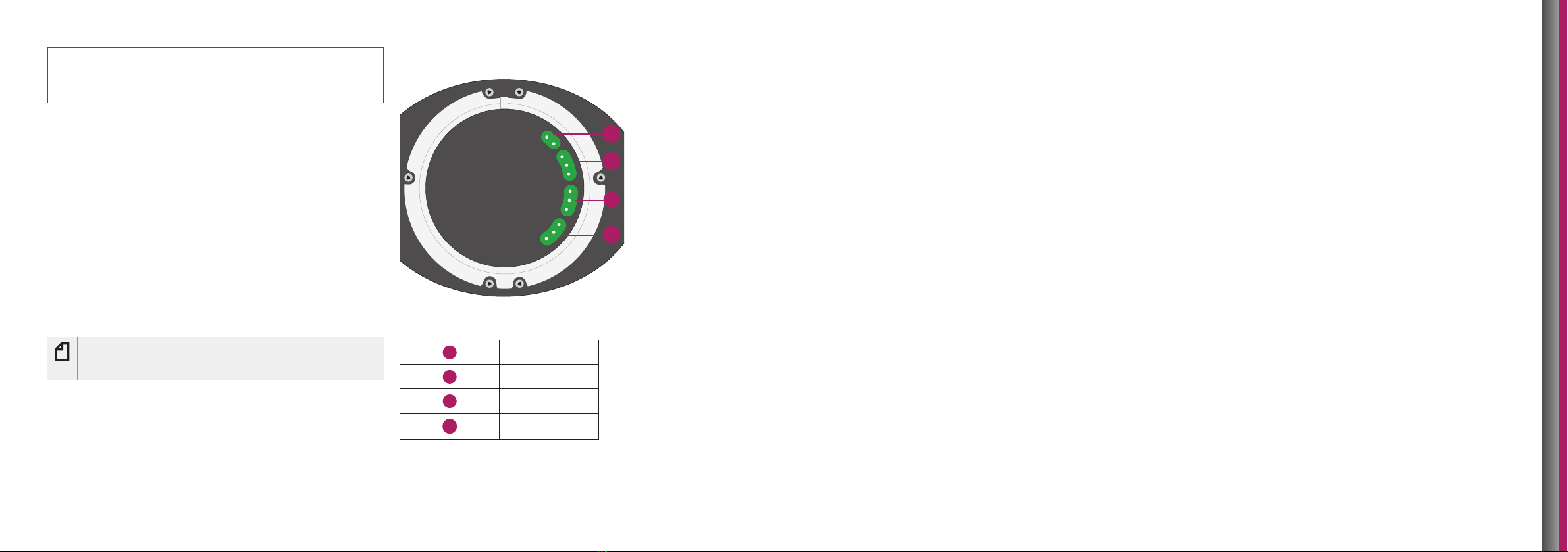
2.2 Input Connector Board
There are 4 plug receptacles on the input board. The table
below lists the location, the type of input that can be used, and
its setup type.
Input Connector Board - Top View
Board Location Input Option
1Battery
2Electrode-Close
3Electrode-Open
4Switch
2.3 Connecting Cables to the Input Board
1. Apply silicone grease to the plug connectors before
inserting into the board.
2. When attaching cables, note the proper orientation. The
connectors are “keyed” or asymmetrical to assure proper
alignment. The connector should plug in easily and is
held in place with friction.
3. Once the cables are attached, apply more silicone grease
on top of the connectors to prevent moisture from
entering receptacles.
4. When removing cables, pull close to the connector to
avoid pulling on the wires. Wires that become loose
could cause intermittent operation.
1
2
3
4
8 | Espire Elbow Technical Manual - Classic Plus, Classic and Basic Espire Elbow Technical Manual - Classic Plus, Classic and Basic | 9
SECTION 3 - BATTERY
INSTALLATION (CLASSIC PLUS)
3.1 Battery Installation
Internal Batteries from Steeper
Steeper 3500S batteries can be used to power the hand and
wrist. For ordering information, please view the Steeper Upper
Limb Catalogue or visit www.steepergroup.com. Batteries
may be installed above or below the elbow and must be
in conformance with all applicable safety and operational
specifications.
Note: Steeper 3500S batteries must be placed within the
elbow compartment as shown on the diagram below,
Above Elbow Battery Location
Batteries that are mounted above the elbow can be connected
to the top of the input board using the input board of the
Classic plus and input wire supplied by the battery manufacturer
(see section 2). A pre-installed pathway routes battery power
from above the elbow to the distal end of the forearm (see
section 4.2).
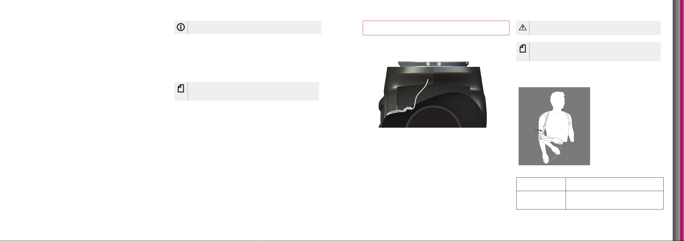
Below Elbow Battery Location
The Espire Classic Plus provides a compartment on the bottom
side of the elbow for housing the 3500S batteries and, if
needed, other manufacturers’ batteries. Other manufacturers’
batteries can be installed in this compartment, providing the
battery dimensions fit without modifying the arm.
1. Route the battery wire through the hole inside of the
compartment into the forearm.
2. Substitute the pre-installed power output wire for one
supplied by the battery manufacturer, then route the
wire through the forearm.
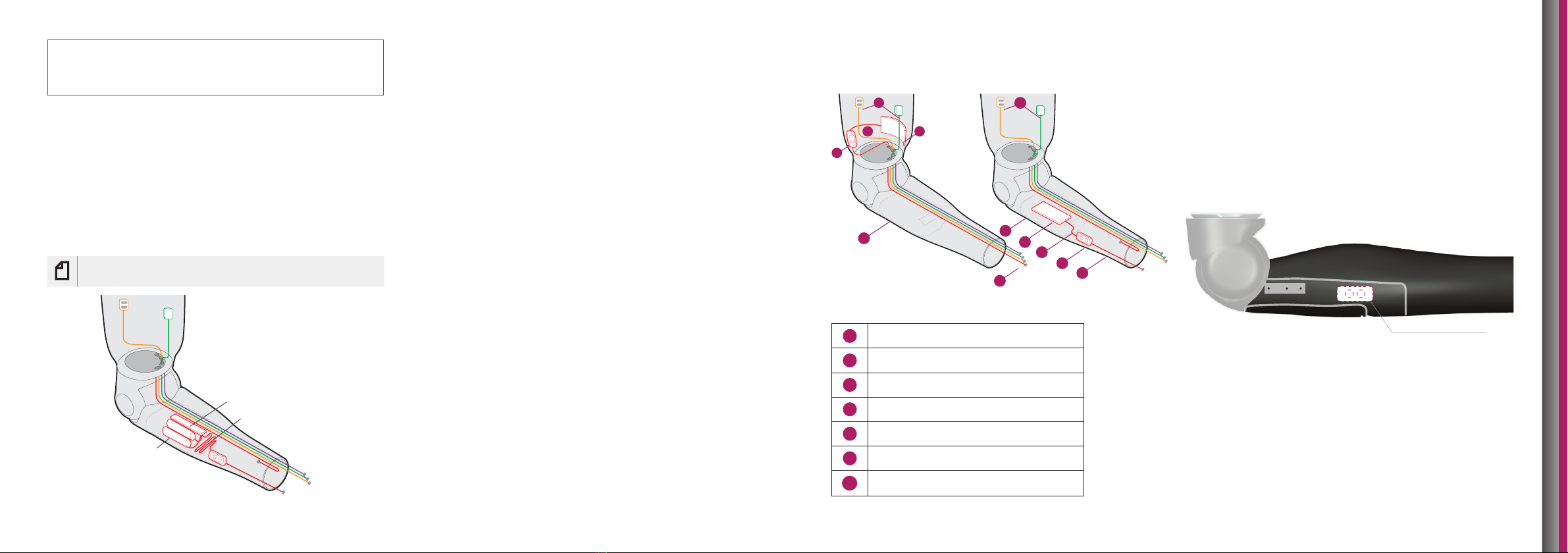
Example Configurations
Above Elbow Location Below Elbow Location
Component
1Electrodes
2Battery
3Battery Wire
4Charging Port/Power Button
5Battery Compartment
6a Power Output Wire (pre-installed)
6b Power Output Wire
11
4
3
3
2
2
55
6a 6b
4
3.2 Charging Port/Power Button
For below elbow locations, a charging port/power button can
be mounted anywhere on the forearm. To prevent damage,
avoid the grey shaded areas and seam lines when drilling
holes. Attach the unit according to the manufacturer’s
recommendations.
NOTE: Do not drill in grey shaded areas or on grey seam lines
Example Location
Hub
Additional Cable
3500S Batteries
10 | Espire Elbow Technical Manual - Classic Plus, Classic and Basic Espire Elbow Technical Manual - Classic Plus, Classic and Basic | 11
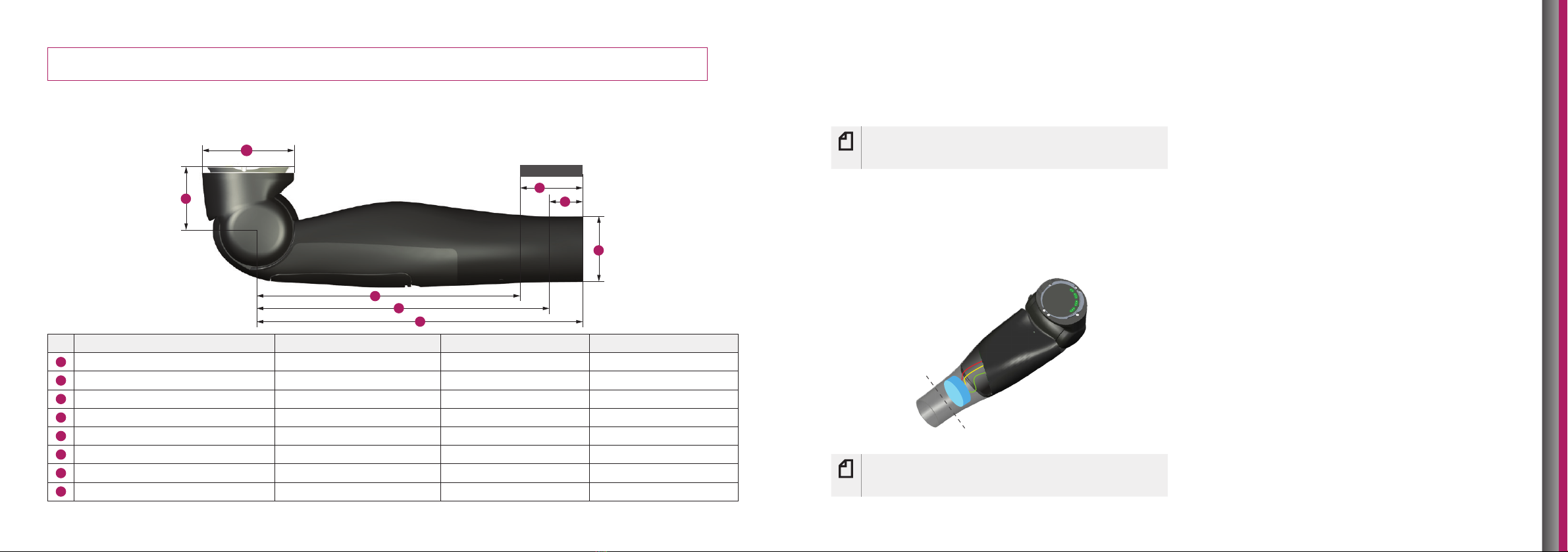
SECTION 4 - MEASURING AND CUTTING FOREARM
4.1 Measuring the Forearm
The Espire Elbow is available in two forearm lengths, Small (45mmØ wrist) and Standard (50mmØ wrist). Forearm measurement
can be referenced from the centre of the elbow. A removable sticker is applied to the forearm to reference the maximum cut area.
MAX CUT AREA
3
2
8
7
1
4
5
6
Dimension Measured From Small Standard
1Diameter - Wrist --- 45 mm 50 mm
2Diameter - Upper Arm Connection --- 70 mm/2.74 in 70 mm/2.74 in
3Minimum Build Height Residual Limb to Elbow Centre 48 mm/1.89 in 48 mm/1.89 in
4Overall Length Elbow Centre 248 mm/9.75 in 273 mm/10.73 in
5Minimum Length – w/rotator Elbow Centre 222 mm/8.75 in 225 mm/8.86 in
6Minimum Length – w/out rotator Elbow Centre 200 mm/7.88 in 225 mm/8.86 in
7Maximum Cut Area – w/rotator Distal End 25 mm/1.00 in 48 mm/1.875 in
8Maximum Cut Area – w/out rotator Distal End 48 mm/1.875 in 48 mm/1.875 in
4.2 Protective Foam Insert
(Classic Plus)
A foam insert is installed prior to shipping to protect the output
wires and to prevent dust or debris from entering the elbow.
Note: Foam insert must be in place prior to cutting the
forearm and completing wrist fabrication. Failure to use
the insert will damage the Espire Elbow.
4.3 Cutting the Forearm to Length
1. Measure the desired length of the forearm.
2. Cut the forearm, preferably with a bandsaw.
3. Continue with wrist fabrication.
Note: It is important to avoid subjecting the system to
excessive vibration such as that caused by a carbide-tip
saw blade or a sanding belt/disk.
12 | Espire Elbow Technical Manual - Classic Plus, Classic and Basic Espire Elbow Technical Manual - Classic Plus, Classic and Basic | 13
SECTION 5 - WRIST
FABRICATION
5.1 Wrist Options Overview
The Espire Elbow accommodates two wrist sizes. Wrist
options are available from multiple manufacturers and the
compatible option depends on the Espire model. Refer to
the manufacturer’s instructions for fabrication and assembly
information.
Small Elbow Standard Elbow
Wrist Size 45 mm 50 mm
Espire Model Wrist Option
Classic, Basic Mechanical Wrist, Friction Wrist, Heavy
Duty Wrist, Short Wrist, Child’s 2-knob
Wrist (Small Elbow only)
Classic Plus Quick Disconnect Wrist, Electronic Wrist
Rotator, Friction Wrist, Short Wrist
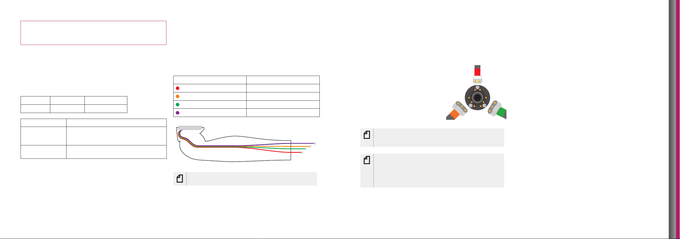
5.2 Output Wires for Terminal Devices (Classic
Plus)
Output wires will already be installed into the circuit board of
the Espire Elbow Classic Plus. They can easily be retrieved from
inside of the forearm and connected to the desired device. The
wires will be colour coded and simply need to be plugged into
the appropriate terminal device. Wires that are not needed can
be tucked away into the forearm.
Colour Output Type
(Red) Power
(Orange) Hand-Open
(Green) Hand-Close
(Purple) Switch
Note: If mounting the battery in the forearm please
refer to section 3 for further details.
1
22
5.3 Quick Disconnect Wrists (Classic Plus)
Wiring
The hand-open, hand-close, and power output cables will
plug into a single coaxial unit which fits through the centre of
the quick disconnect wrist.
1. Plug the orange (hand-open)
cable into the left plug labeled
“2”, then plug the green (hand-
close) cable into the right plug
labeled “2”.
2. Plug the red (power) output
cable into the plug labeled “1”.
Note: If the two 3-socket connectors (hand-open/
hand-close) are attached to the wrong plugs labeled
“2”, the open-close functions will operate in reverse.
Note: If fitting with a short wrist or friction housing but
still want batteries above elbow, the cable option uses
dierent connector. Therefore, if using power with the
Classic version it would require external wiring if power
proximal to the elbow joint was needed. If integrated
power is desired, the Classic Plus would be advisable.
5.4 Electronic Wrist Rotators (Classic Plus)
Electronic wrist rotators require a battery that supplies an
additional plug for the wrist power (See section 3.1). To connect
a wrist rotator, install the battery in the forearm and use that
unique system. The wire should be attached to the battery, run
though the distal end of the forearm, and connected to the
wrist. Contact the wrist manufacturer for more information.
14 | Espire Elbow Technical Manual - Classic Plus, Classic and Basic Espire Elbow Technical Manual - Classic Plus, Classic and Basic | 15
SECTION 6 - THE LAMINATION
COLLAR AND CLAMP RING
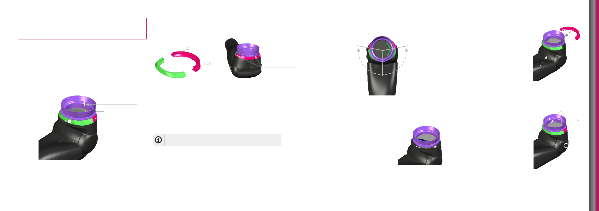
6.1 Orientation of the Lamination Collar and
Clamp Ring
The lamination collar must be oriented properly relative to the
patient socket to allow for correct internal / external humeral
rotation and to protect the wiring of the Espire Elbow.
Line indicates
posterior
Anti-rotation
stop pin located
internally on the
underside of the
lamination collar
Colours for representation only.
The clamp ring is a two-piece assembly that is uniquely shaped
to fit the profile of the Espire Elbow. When assembled to the
elbow, the clamp screws will face posterior.
6.2 Internal-External Rotation
The Espire is designed with a humeral anti-rotation stop pin to
prevent 360-degree rotation. This feature is to prevent input
wires from being twisted and potentially damaged. The anti-
rotation stop pin allows for 100° external / 100° internal rotation
for a total range of 200°.
Info: Normal human range of motion is 30° externally
and 135° internally.
Humeral Friction
Fasteners
6.3 Attaching the Lamination Collar to the Elbow
1. Disassemble the clamp ring by
removing the fasteners.
2. Place the lamination collar (or
socket with attached collar)
near top of the elbow.
3. Plug appropriate cables into
the input board (if applicable,
see section 2.3).
4. With the laminating collar
in place, insert Clamp Ring
A (green) around both the
anterior end of the lamination
collar and elbow attachment.
5. Then insert Clamp Ring
B (pink) around both the
posterior end of the lamination
collar and elbow attachment.
6. Insert the fasteners and torque,
(hand tighten to start and
then tighten until appropriate
friction is achieved for humeral
rotation). Apply equal torque
to both fasteners.
Top View
Posterior
A
B
Lamination collar
Clamp ring
0°
100° 100°
100° 100°
16 | Espire Elbow Technical Manual - Classic Plus, Classic and Basic Espire Elbow Technical Manual - Classic Plus, Classic and Basic | 17
6.4 Determining Proper Orientation on Test
Socket
The lamination collar attachment to the socket must provide a
clinically acceptable measurement from centre axis of shoulder
to centre axis of elbow. The appropriate elbow carry angle must
also be established, preferably for full extension.
1. Test the collar orientation by placing it under the user’s
test socket with the orientation line facing posterior. It
may be necessary to extend the collar away from the
socket to establish the correct elbow position. Mark where
the collar contacts the socket or extension material.
2. Remove the clamp ring from the lamination collar and
elbow.
3. Temporarily attach the collar to test socket using
fibreglass tape, epoxy or other adhesive. Clean any
residue from the collar surface at the elbow attachment
point.
4. Re-attach the elbow to the lamination collar and test
socket. Rotate the forearm clockwise and anti-clockwise
and verify the stop positions at 100° from centre (see
section 6.2). Rotate the collar accordingly to adjust the
amount of internal or external rotation.
5. Temporarily fit the arm to the user, verify that the
position, carry angle, and elbow centre are appropriate.
Record the data.
6. Create a new mould for the definitive socket. Transfer the
measurements and position from the test socket.
7. Fabricate the definitive socket with sensors and applicable
prosthetic materials.
SECTION 7 - MANUAL LOCK
7.1 Manual Lock Overview
The Espire features a mechanical locking mechanism that
can be locked or unlocked while under load, with a maximum
support of 25lbs/11kg.
The manual lock cable is attached to the upper elbow assembly,
near the midline. The lock can be engaged/disengaged every
10° (13 positions). A strain-relief is included to reduce the
likeliness of damage due to excessive pull on the lock cable.
The lock cable can be used with or without the Steeper Harness
System. Attach the cable to a harness using your preferred
mounting method. The cable may be shortened, but do not
remove it completely.
For further details on the Steeper Harness System please view
the Steeper Upper Limb Catalogue.
Caution: Complete removal of the manual lock cable
can lead to malfunction and injury to the user.
Note: The manual lock is not removable or field-
serviceable. Do not attempt to disassemble or modify
the unit.
7.2 Operating Manual Lock
Pull on the lock cable to
engage/disengage the
lock. Lock response will
vary by the amount of
force applied.
Standard Lock-
Unlock
A strong cable pull (clicking sound)
disengages or re-engages the lock.
Temporary Unlock A light cable pull (no click) unlocks the
elbow joint temporarily. Relieving the
cable tension re-engages the lock.
Info: For more information on lamination, see Espire
Elbow Fabrication Instructions.
6.5 Final Adjustment with the User
The humeral rotation is adjusted with a 2.5mm hex key that
is supplied with the clamp ring. While the user is wearing the
prosthesis, adjust the friction until it is most comfortable. This
friction can be adjusted as needed.
Note: Over tightening this screw may damage the
screw threads. Use small, controlled adjustments until
the desired amount of friction is reached.

18 | Espire Elbow Technical Manual - Classic Plus, Classic and Basic Espire Elbow Technical Manual - Classic Plus, Classic and Basic | 19
SECTION 8 - CABLE MOUNTING
8.1 Cable Mounting Overview
Your preferred cable system can be mounted to the forearm to provide elbow flexion and/or
prehensile control.
A cable mounting bracket is located internally, (both medially and laterally). Three indentations
on the surface of the forearm indicate where a hole may be drilled to attach the cable loop. The
recommended starting point is the first hole (closest to elbow centre). The closer to the joint the
bracket is located the more force is required to flex the elbow.
8.2 Setting Up the Cable Mounting
Drill Mounting Hole
A (17/64in or 6.75mm) drill bit and collar are provided to control the depth of the hole that is drilled.
Carefully drill the mounting hole. Do not drill beyond the forearm shell surface or contact
the internal mounting bracket.
Recommended
Starting Point
3 cm
Attach Cable Loop
(or preferred cable anchor)
1. Fold the leather cable loop and fasten together with the rivet.
2. Align the cable loop to the hole. Attach with a 10-32 fastener and hand tighten.
3. Attach your preferred cable system to the prosthesis.
20 | Espire Elbow Technical Manual - Classic Plus, Classic and Basic Espire Elbow Technical Manual - Classic Plus, Classic and Basic | 21
SECTION 9 - SETTING UP THE
COUNTERBALANCE OR SPRING
ASSIST
9.1 Counterbalance and Spring Assist Overview
Depending on which model you are using, the Espire will include
either a counterbalance or spring assist mechanism:
Espire Model Lift Compensation Aid
Classic Plus, Classic Counterbalance
Basic Spring Assist
Both the counterbalance and spring assist aid in flexion and
extension of the Espire Elbow. Dierent amounts of tension are
necessary based on the elbow’s overall length, the weight of the
terminal device, and the type of clothing worn.
Note: The counterbalance and spring assist
mechanisms are not removable or field-serviceable. Do
not attempt to disassemble or modify the unit.
Adjustment Dial Location
The adjustment dial can be installed on either the medial or
lateral side of the elbow and should be specified at the time of
ordering. Medial placement is the typical location.
The dial is identical for both counterbalance and spring assist.
However, these mechanisms adjust in opposite directions (see
sections 9.2 and 9.3).
Note: Adjustments are easier to make when the
forearm is flexed.
Caution: Be aware that if the adjustment dial is at
maximum tension and the arm is raised to a horizontal
level, the elbow could suddenly flex.
Caution: To prevent injury, users should ensure the
elbow is in the maximum flexed position when donning
or dong.
Adjustment Dial
Example: left arm with medial
adjustment location
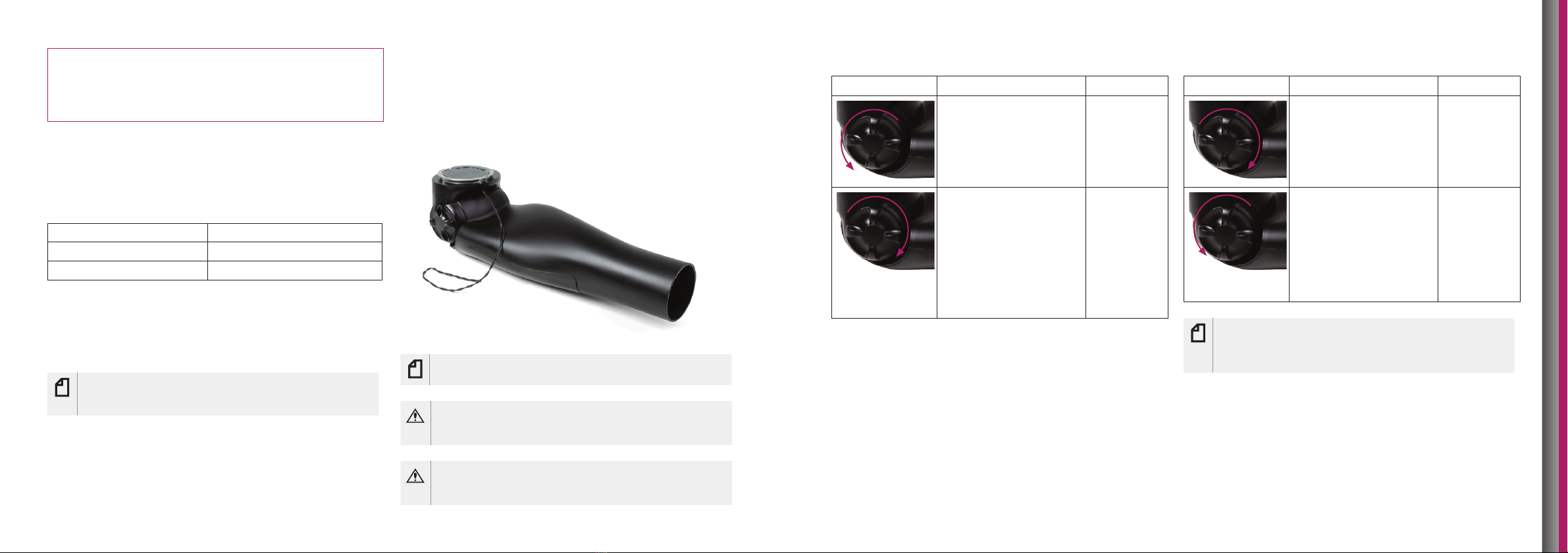
9.2 Counterbalance Adjustment
Direction Adjustment Result
Turn the dial posteriorly
to increase the
counterbalance weight.
Note: Elbow cannot be
over-adjusted in this
direction, it will simply
reach maximum flexion.
Supports
more load on
the elbow
Turn the dial anteriorly
to decrease the
counterbalance weight.
Note: Elbow will spring
back into flexion
according to how much
spring lift assist is put into
the system if it exceeds
the minimum adjustment.
Supports
less load on
the elbow
9.3 Spring Assist Adjustment
Direction Adjustment Result
Turn the dial anteriorly to
increase the spring assist
weight.
Note: Elbow cannot be
over-adjusted in this
direction, it will simply
reach maximum flexion.
Supports
more load on
the elbow
Turn the dial posteriorly
to decrease the spring
assist weight.
Note: Elbow will spring
back into flexion
according to how much
spring lift assist is put into
the system if it exceeds
the minimum adjustment.
Supports
less load on
the elbow
Note: The direction of adjustment would be opposite
if on the lateral aspect of the elbow. There is a sticker
that indicates + or – on the dial to indicate more or less
assist to lift.
22 | Espire Elbow Technical Manual - Classic Plus, Classic and Basic Espire Elbow Technical Manual - Classic Plus, Classic and Basic | 23
SECTION 10 - MAINTENANCE
AND TROUBLESHOOTING
10.1 Troubleshooting
For troubleshooting connection issues on the Classic Plus,
contact your local distributor or Product Manager for support.
Caution: The Espire Elbow should never be serviced
while connected to the end-user. Ensure that the device
is disconnected and powered o before any service or
maintenance is performed. This device should never
be serviced while in use. Never let children handle this
device unsupervised. Take caution when using this
device around pets that may cause damage to the
device.
10.2 Maintenance
The Espire Elbow cannot be maintained in the field, and must
be returned for repair/service. For support on maintenance
please contact your local distributor or Product Manager.
SECTION 11 - INTENDED USE
AND SAFETY
11.1 Intended Use
Intended Use Statement
The Espire Elbow is to be used exclusively for external
prosthetic fittings of the upper limbs.
Intended Users
The Espire Elbow is intended for use only by the individual
being fitted with the device. The manufacturer does not
approve use by any other person/s. The Espire Elbow system
is to be purchased, configured and fit only by a qualified
prosthetist.
11.2 Indications and Contraindications
Indications for use of the Espire Classic Plus, Classic or Basic
elbow systems include the following:
• Adequate limb length to allow for appropriate socket
fit at a level above the elbow. This would include elbow
disarticulation, transhumeral, shoulder disarticulation and
forequarter
• Adequate muscle activity and range of motion of shoulder
joint to adequately control a body-powered prosthetic
device
11.3 Safety
Please ensure that the user is fully aware of all the safety
instructions before they leave the clinic,
Note: Possible technical damage.
Info: Basic information regarding this product.
Caution: Possible risk of accident or injury.
Warning: Possible risk of severe accident or injury.
Caution: Failure to follow the safety instructions that
follow can lead to damage or malfunction of the
product. Follow the safety instructions and stated
precautions in this document.
• Appropriate sound side limb dexterity or assistive device to
position and lock elbow system for use where necessary
• Adequate muscle activity for myoelectric control (Classic
Plus only)
• Adequate cognitive ability to master technology and input
requirements of device (Classic Plus only)
• The patient is able and willing to participate in training for
use of the myoelectric control of the prosthesis
• Access to a qualified prosthetist for fitting and servicing of
the elbow system
• Able and willing to charge power source on a daily basis
(Classic Plus only)
Contraindications for use of the Espire Classic Plus, Classic, or
Basic elbow systems include the following:
• Any condition that prevents socket fitting, such as a
complicated wound or intractable pain which precludes
socket wear
• Inability to tolerate the weight of the prosthesis
• Inability to produce muscle or body movement necessary for
operation of the terminal device(s)
• Significant deformity of remaining limb that would impair
the ability to operate body-powered devices
• Specific environmental factors—such as excessive moisture
or dust, or inability to clean or maintain the prosthesis

24 | Espire Elbow Technical Manual - Classic Plus, Classic and Basic Espire Elbow Technical Manual - Classic Plus, Classic and Basic | 25
Safety Instructions
Info: Disposal
These products may not be disposed of with household waste
in some jurisdictions. Disposal that is not in accordance with
the regulations of your country may have a detrimental impact
on health and the environment. Please observe the information
provided by the responsible authorities in your country
regarding return and collection processes.
Caution: Manipulation of system components
Independent changes and/or modifications to system
components may lead to faulty control or malfunction of the
Espire Elbow, resulting in a risk of injury. No modifications of
the Espire Elbow except those described in this information
document are authorised. The Espire Elbow and damaged
components may only be opened or repaired by certified
Steeper technicians.
Caution: Penetration of dirt and humidity
The penetration of dirt and humidity may lead to faulty control
or malfunction of the Espire Elbow and result in a risk of injury.
Ensure that neither solid particles nor liquids penetrate the
Espire Elbow.
Caution: Mechanical overloading
External mechanical influences or loads, such as impacts and
vibration, can lead to faulty control or malfunction of the Espire
Elbow and result in a risk of injury. The Espire Elbow should not
be subjected to mechanical vibrations or impacts.
Caution: Thermal overloading
Extreme temperature conditions can lead to faulty control or
malfunction of the Espire Elbow and result in a risk of injury.
Avoid areas outside the specified operating temperature range.
The operating temperature range must be between 5°C and
40°C (41°F and 104°F).
Caution: Improper use
Any type of excessive strain, overload or improper use may
lead to faulty control or malfunction of the Espire Elbow,
resulting in a risk of injury. The Espire Elbow was developed
for everyday use and must not be used for unusual activities.
These unusual activities include, for example, sports with
excessive strain and/or shocks to the wrist joint (pushups,
downhill mountain biking, etc.) or extreme sports (free
climbing, paragliding, etc.). Not for use when swimming or in
wet environments. Careful handling of the prosthesis and its
components not only increases their service life but, above
all, ensures your personal safety. Should the prosthesis be
subjected to unusual stresses (such as a fall), immediately
contact a qualified prosthetist and have the prosthesis
inspected for any damage.
Caution: Consequences of product deterioration
Wear and tear on system components can lead to malfunction
of the Espire Elbow, resulting in a risk of injury. The service life
of this device is 2 years for device parts and accessories.
Caution: Water and Humidity
The electrical and mechanical systems of your Espire Elbow are
not water-resistant. Water must be prevented from entering
the Espire Elbow. Be careful not to let water run over the top
of the prosthetic glove and enter the Espire Elbow as well as
the terminal device. If water enters the inside of the prosthesis
for any reason, immediately switch o all components and
stop using or charging them. A qualified prosthetist must be
contacted immediately to assess the device and avoid further
damage.
Caution: Risk of Accident While Operating a Vehicle
An upper extremity amputee’s ability to drive a vehicle is
determined on a case-by-case basis. Factors include the type
of fitting (amputation level, unilateral or bilateral, residual
limb conditions, design of the prosthesis) and the amputee’s
abilities. All persons are required to observe their country’s
national and state driving laws when operating vehicles. For
insurance purposes, drivers should have their driving ability
examined and approved by an authorised test centre. For
maximum safety and convenience, Steeper recommends
that, at the very least, a specialist evaluate the need for any
adaptations to the car. It is indispensable to ensure that the
driver can operate the vehicle without any risk with the Espire
Elbow turned o. A doctor or prosthetist should be consulted
before operating a motor vehicle with this device; otherwise
the Espire Elbow is not approved for use whiling driving.
Caution: Risk of Pinching Where The Elbow Joint Bends
Ensure that fingers and other body parts are not in this area
when bending the elbow joint.
Caution: Unsupervised Use
It is not recommended for children to operate this device
without the supervision of an adult. Use extreme caution
around small children and household pets.
Warning: Using with Other Equipment
Use of this equipment adjacent to or stacked with other
equipment should be avoided because it could result in
improper operation. If such use is necessary, any equipment
needs to be agreed appropriate with their Prosthetist and/or
Steeper.
Warning: Use Only Specified Equipment
Use of accessories, transducers and cables other than those
specified or provided by the manufacturer of this equipment
could result in increased electromagnetic emissions or
decreased electromagnetic immunity of this equipment and
result in improper operation.
Complies with Standards
No. Description Version
ISO 22523 External limb prostheses and
external orthoses – Requirements
and test methods
2006
26 | Espire Elbow Technical Manual - Classic Plus, Classic and Basic
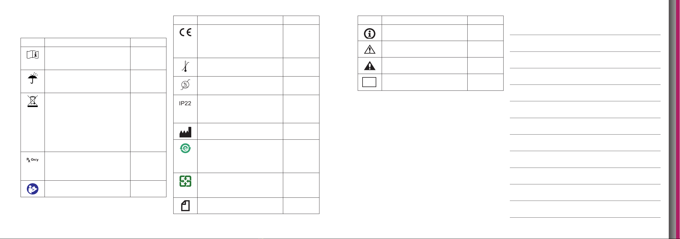
Definitions of symbols used in and on this device
and packaging
Symbol Definition Source
Consult instructions for use. BS EN ISO
15223-1: 2012
Reference no.
5.4.3
Keep dry. BS EN ISO
15223-1: 2012
Reference no.
5.3.4
This product contains electrical and
electronic components that may
contain materials which, if disposed
with general waste, could be damaging
to the environment. Residents of the
European Union must follow specific
disposal or recycling instructions
for this product. Residents outside
the European Union must dispose or
recycle this product in accordance with
local laws or regulations that apply.
IS EN
50419:2006
Reference no.
Fig. 1
Caution: Federal (USA) law restricts this
device to sale by or on the order of a
physician.
USA Code
of Federal
Regulations
21 CFR Part 801
§ 801.109(b)(1)
Refer to instruction manual/booklet. IEC TR 60878
Ed. 3.0 b:2015
Symbol Definition Source
The requirements for accreditation
and market surveillance relating to the
marketing of products; Medical Device
Directive.
765/2008/EC
768/2008/EC
MDD 93/42/
EEC Articles
4,11,12,17, Annex
II )
Temperature limit. ISO 15223-1
Reference no.
5.3.7
Storage humidity range. ISO 15223-1
Reference no.
5.3.8
Protection against solid foreign objects
of 12.5 mm diameter and greater, and
protection against vertically falling
water drops when tilted up to 15
degrees.
IEC 60601-
1, Table D.3,
Symbol 2
Medical device manufacturer. ISO 15223-1,
Clause 5.1.1
China RoHS Mark I logo. Product
does not contain toxic and hazardous
substances or elements above the
clip level in any material or application
including those exempt from the
requirements of the EU RoHS Directive.
SJ/T11364-
2006
Subject to recycling under the Waste
Disposal Act.
Environmental
Protection
Administration,
R.O.C.(Taiwan)
Note: Possible technical damage.
Additional Notes
Symbol Definition Source
Info: Basic information regarding this
product.
Caution: Possible risk of accident or
injury.
Warning: Possible risk of severe
accident or injury.
Indicates that this item is a medical
device
MD
MADE IN THE UK
©2020 Steeper Group
All rights reserved.
Steeper Group, Unit 3 Stourton Link,
Intermezzo Drive, Leeds, UK, LS10 1DF
Steeper Group
Unit 3 Stourton Link, Intermezzo Drive
Leeds, LS10 1DF
Tel: +44 (0) 870 240 4133
Email: customerservices@steepergroup.com
SteeperUSA
8666 Huebner Road, Suite 112
San Antonio, TX 78240
Tel: (+1) 210 481 4126
Email: inquiries@steeperusa.com
STPPR126 Issue 1 November 2020
This manual suits for next models
2
Table of contents
Other Steeper Medical Equipment manuals


