Medicatech MasterRad30 User manual

Page 1of 15
Rev. 01
Installation Manual
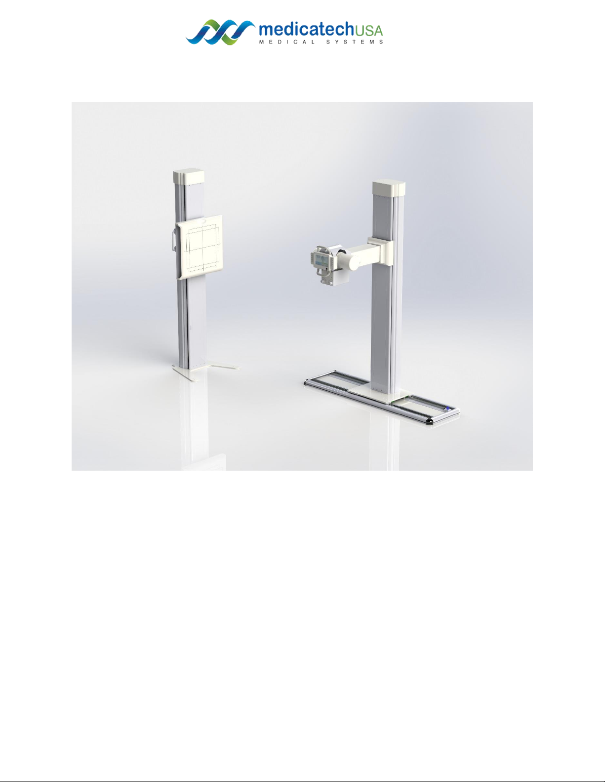
MasterRad30
Universal Radiographic System

Page 2of 15
Rev. 01
Introduction:
Important! .. X-ray Protection
X-RAY EQUIPMENT IS DANGEROUS TO BOTH PATIENT AND OPERATOR UNLESS
MEASURES OF PROTECTION ARE STRICTLY OBSERVED
X-ray equipment if not properly used may cause injury. Accordingly, the instructions herein
should be thorougly read and understood before attempting to place this equipment in
operation. We will be glad to assist and cooperate in placing this equipment
Although this apparatus I built to the highest safety and incorporated a high degree of
protection against x-radiation other than the useful beam, no practical precautions to prevent
the possibility of any persons carelessly, unwisely, or unknowingly exposing themselves or
other to x-radiation.
It is important that everyone working with x-radiation be properly trained and take adequate
steps to insure protection against injury. The manufacturer assumes that all operator and
service personnel authorized to use, install, calibrate an maintain this equipment is cognizant of
the danger of excessive exposure tp x-radation, is sufficiently trained and has the required
knowledges for it. The equipment herein described which may result from exposure to x-
radiation.
Various protective material and devices are availablt. It is recommended that such materials
and devices be used

Page 3of 15
Rev. 01
SECTION 1: INSTALLATION
1.1 TOOLS
The following hand tools are required for the installation:
•Standard service engineers tool kit.
•Electric drill motor and assorted bits.
1.2 Pre-installation checks
Prior to beginning installation, it is recommended to inspect the sire and verify that
the x-ray room complies with requirement such as:
•Space requirements to allow installation and system movements must
consider the maximum dimensions and travels of the equipment.
Maximum Height 96 in (8 ft)
Maximum Width 132 in (11 ft)
Maximum Length 180 in (15 ft)
•Conduits and walls are ready to install the system.
•Electricity installation:
oMain supply: Single phase, 50/60 Hz
115/208/230/240 V ~
•Minimum Power input required: 400 VA
Page 4of 15
Rev. 01
Page 5of 15
Rev. 01
1. Hardware Installation:
1.1. Refer to the layout of the room
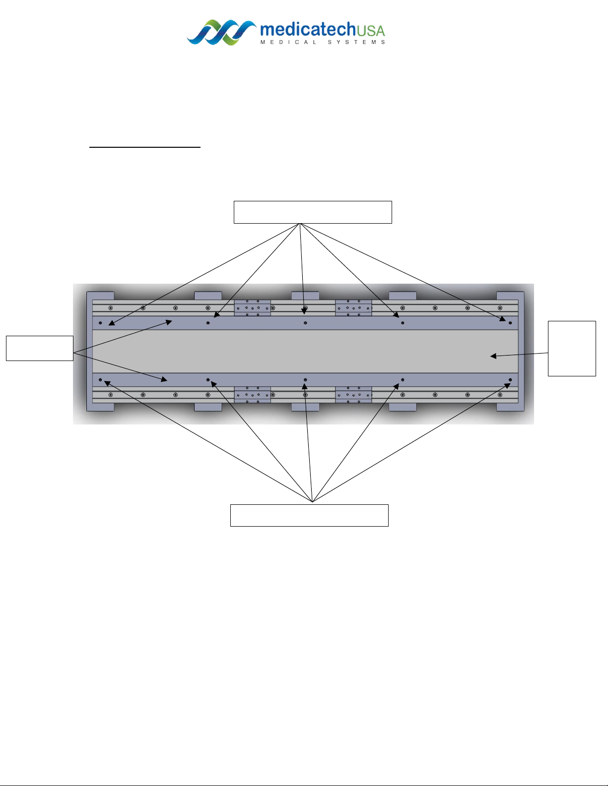
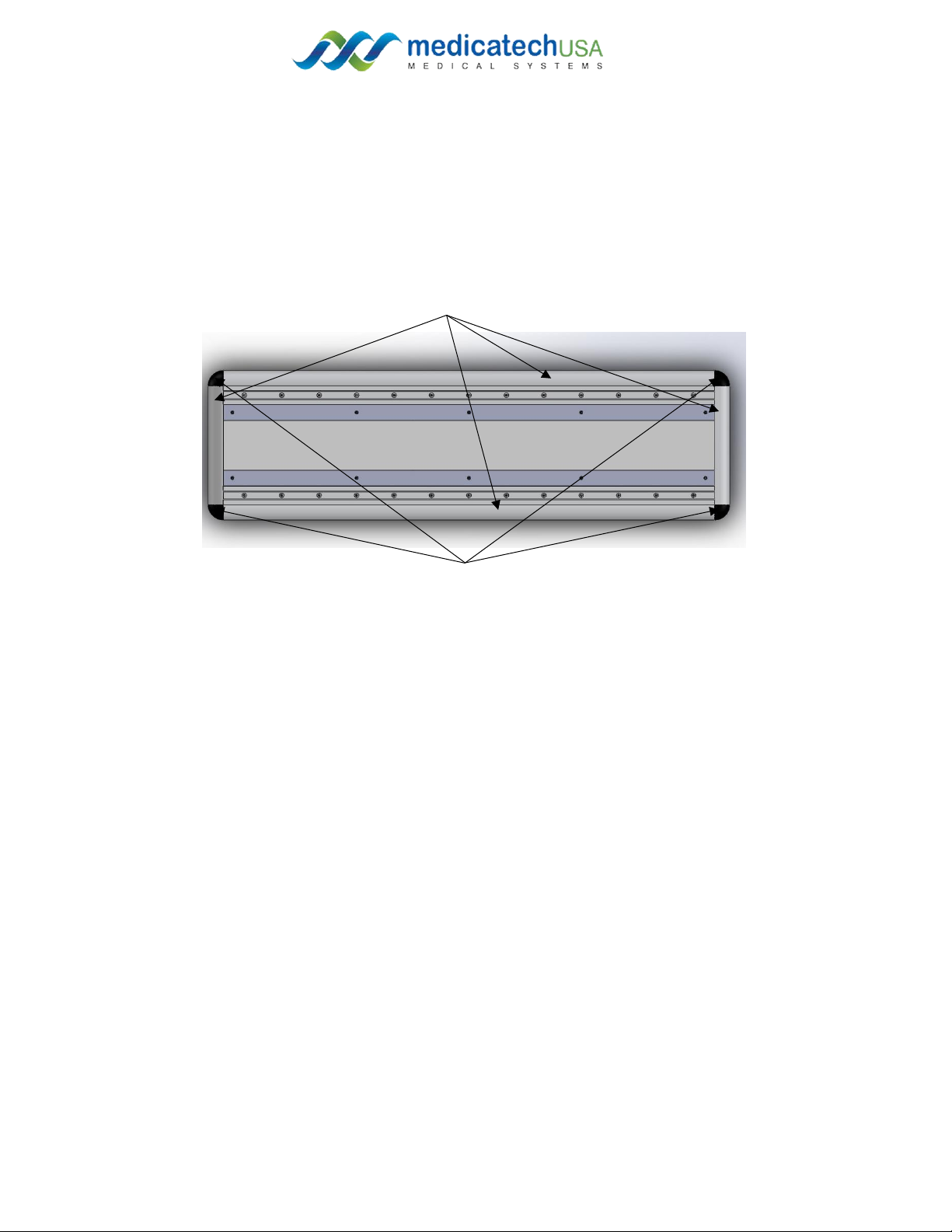
1.2. Locate and unscrew the 10 x allen flat head screws #10-32 screws
Figure 1:take the bare strips and the floor mount cover
1.3. Take off the 2 brake strips and the floor mount cover
1.4. Place the floor mount 6” from the back wall.
1.5. Mark the place of the anchor on the floor.
5x Allen flat head #10-32 screws
5x Allen flat head #10-32 screws
Brake strips
Floor
mount
cover
Page 6of 15
Rev. 01
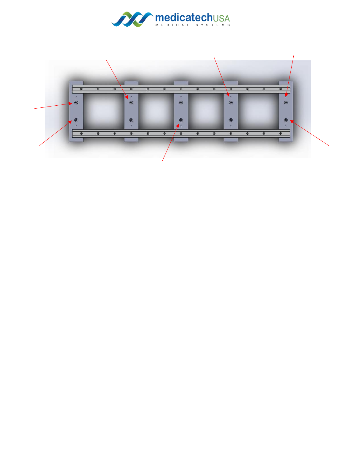
1.6. Using a 3/8” cement drill bit, Drill 7 mounting holes (refer to figure 2)
1.7. Place the washer and the nut on the anchor, as it will be hard to place them after
hammering the anchors in the floor.
1.8. Use the hammer to fix the anchor into the ground. (Make sure that the anchors are
deep enough in the floor, so it will clear the cover on top. )
1.9. Place the top cover and the 2 brake strips using the provided screws. (refer to figure 1)
1.10. Place the tube stand on the floor mount. (figure 3) (requires 2 people minimum)
Figure 2: floor mount mounting holes
Page 7of 15
Rev. 01
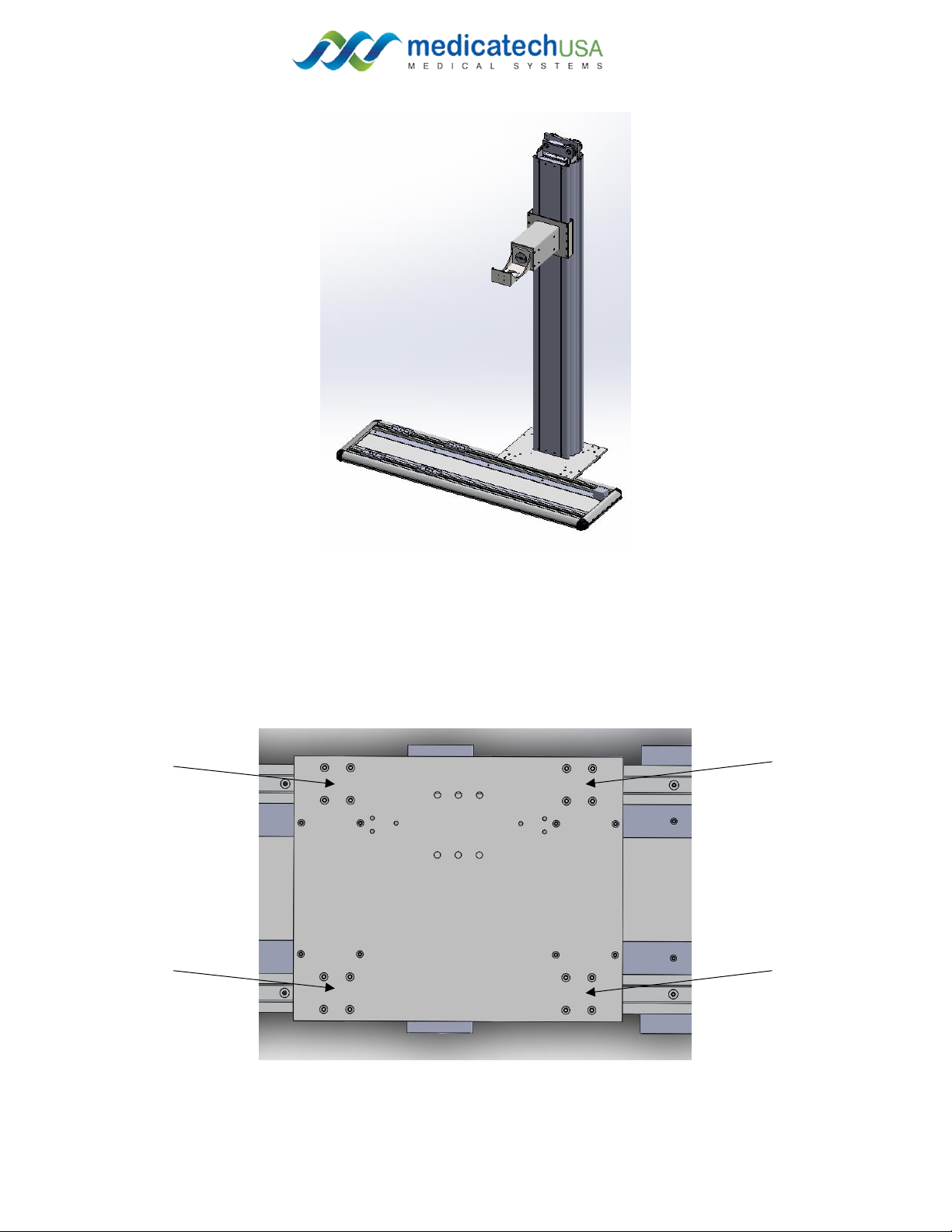
Figure 3:place the tube stand on the floor mount.
1.11. Align the tube mount base with the 4 carts on the floor mount.
1.12. Use the 16 xM6 screws to connect the tube stand to the floor mount. (figure 4)
Figure 4: 16x M6 screws
Page 8of 15
Rev. 01
1.13. Place the 4 side covers and the 4 corners simply by connecting them and place
them around the floor mount (refer to figure 5)
1.14. Make sure that the side cover with the cable tray attached is at the back side.
1.15. Connect grey draw wire sensor at the back right of the floor mount at its
designated place. (use the three screws provided)
1.16. Place the sensor’s cover by inserting the cover’s lip into the floor mount cover’s
grove.
1.17. Connect the wire to the cart.
1.18. Guide the wire through the cable tray and to the relay at the back of the tube
stand.
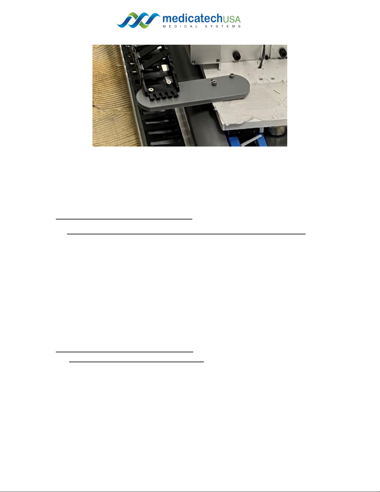
1.19. Locate black draw wire sensor at the bottom of the tube stand.
1.20. Attached the wire to the bottom of the arm holder.
1.21. Mount the control panel through the 4 provided screws on the front of the arm.
1.22. Attach the bracket provided to the top of the tube stand.
1.23. Mount the front cladding (extrusion) to on the bracket.
1.24. Repeat 1.22 and 1.23 for the chest stand.
1.25. Attach the plastic part at the end of the cable tray to the cart (use the designated
supplied screws)
Side covers
Figure 5: showing the top cover, brake strips, side cover and corner.
Corners
Page 9of 15
Rev. 01
Tube , collimator, and generator installation
(all cables are going to the back of the tube stand and through the cable tray)
1.26. Place the tube on top of the arm.
1.27. Place the collimator ring at the bottom of the arm below the tube through the
arm
1.28. Place the collimator below the arm as shown in the picture, then screw the
collimator inside screws to fix the collimator to the collimator ring.
1.28.1. (refer to the collimator Manual)
Refer to the following pages for proper cable management and connections for the tube,
collimator and generator
2. Collimator, Tube, and generator installation:
2.1. Collimator: (refer to the collimator manual)
2.1.1. Align the tube using the screws found with the
metal plates inside of the blue binder. (note: there
are two different types of screws used according to
the type of X-ray tube).
2.1.2. Thereare two main tools used to install
collimator;
2.1.2.1. Allenkey for screws
2.1.2.2. Allenkey for the mounting plate
Page 10 of 15
Rev. 01
2.1.3. remove the collimator mounting plate
2.1.4. connect the collimator mounting plate to the tube using the screws previously
used to align and keep tube in place
2.1.5. place collimator on to mounting plate and tighten all four screws in order to
secure collimator on the tube arm
2.1.6. connect collimator to CPI generator cable then other collimator cable located at
the back of the table to foot pedal cable ( there is only one way to connect the
cables)
Figure 8: showing the 4 mounting holes at the bottom of the arm to mount the tube and the collimator ring
2.2. Tube: (refer to the generator and the tube manual)
2.2.1. Place tube on holder so that it is stable
2.2.2. Unscrew the tap (be gentle with cap screws as they are easy to strip)
2.2.3. Grey tube wire is connected to the tube with the wire side labeled 1,2,3, etc.
2.2.4. Connect the grey wire as follow inside the tube to its relative number: (refer to
figure 9)
2.2.4.1. Black wire is 1
2.2.4.2. Red wire is 2
2.2.4.3. Yellow wire is 3
2.2.4.4. White wire is 5
2.2.4.5. Blue wire is 6
2.2.5. Get the wire through the built in zip tie in order to adjust the fix the wgrey wire
in place inside the tube

Page 11 of 15
Rev. 01
2.2.6. Screw the cap back on
2.2.7. Feed the loose end of the grey cable through the arm and through to the bottom
access point
2.3. Generator connections:
2.3.1. Connect the high-tension cables to the tubes.
2.3.1.1. Connect one cable to the positive end on the tube
2.3.1.2. Connect the second cable to the negative end on the tube.
2.3.2. Remove the cover for the electrical CPI generator
2.3.3. Connect the high-tension cable it their designate place,
2.3.3.1. Apply silicon on the top of the wire head and distribute it all over the
head of the cable, you end up with a thin layer of silicon that cover the head
of high-tension cable.
Figure 9: internal wiring of the tube.

Page 12 of 15
Rev. 01
2.3.3.2. Connect the positive end of the cable to the positive end inside the
generator and so for the negative
2.3.4. Close the generator cover
2.3.5. Organize the cables through the cable tray
2.3.6. Connect the power cable to the wall disconnect.
Note: most of the other wiring are connected for you as a courtesy.
3. Chest Stand mounting:
3.1. Place the chest stand 40” from the nearest edge of the floor mount.
3.2. Make sure it aligns with the laser and the light field from the collimator.
3.3. Mark the anchor places.
3.4. Using the 3/8” cement drill bit (for any other types of flooring, please contact us for the
appropriate fixture), Drill 4 mounting holes.
3.5. Use the 3/8”-16 anchors provided to fix the chest stand to the ground.
Figure 10: connecting the high tension cables to the generator

Page 13 of 15
Rev. 01
4. Electrical connections
4.1. Mount the relay box to the back of the tube stand
4.2. Connect the wires to the relay box as follow:
4.2.1.
1. Use the lemo connector (black wire with silver head)
a. Connect the cable to the back of the control panel.
b. Guided the cable through the top of the arm and to the back of the tube
stand.
c. Connect the cable to the first top connector
2. Connect the floor mount draw wire sensor
3. Connect the tube stand draw wire sensor
4. Skip
5. Connect the power off brakes of the tube stand
Page 14 of 15
Rev. 01
6. Connect the rotation brakes (wire from the arm)
7. Skip
8. Connect the floor mount brakes
9. Skip
10. Skip
11. Power cable
5. DR Panel , workstation installation:
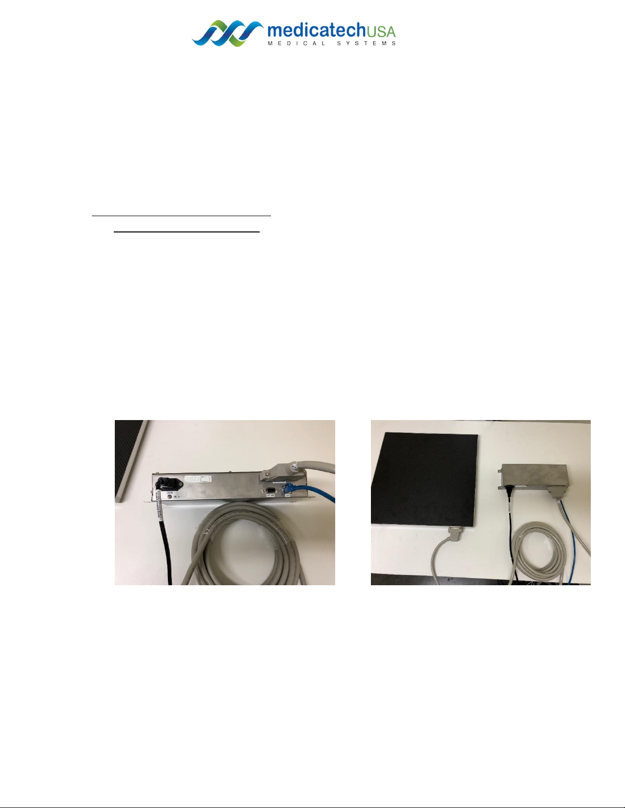
5.1. DR Panel: (refer to figure 11)
5.1.1. Remove the DR panel from the packing (take care don’t drop it or hit).
5.1.1.1. Connect the DR Panel to the power box to the 25 Pin connector’s cable
(female connector).
5.1.1.2. Connect the male side of the cable to the power box.
5.1.1.3. Position the DR Panel inside the table panel bucky.
5.1.1.4. Connect the cat6 cable from power box to the Ethernet port on the
workstation.
5.1.2. to be able to use it, you need to power on both the power box and the
workstation, then open Voyance software on the workstation (Kindly consult the
user manual of Voyance for more details.
Figure 11: view of the DR power box connection

Page 15 of 15
Rev. 01
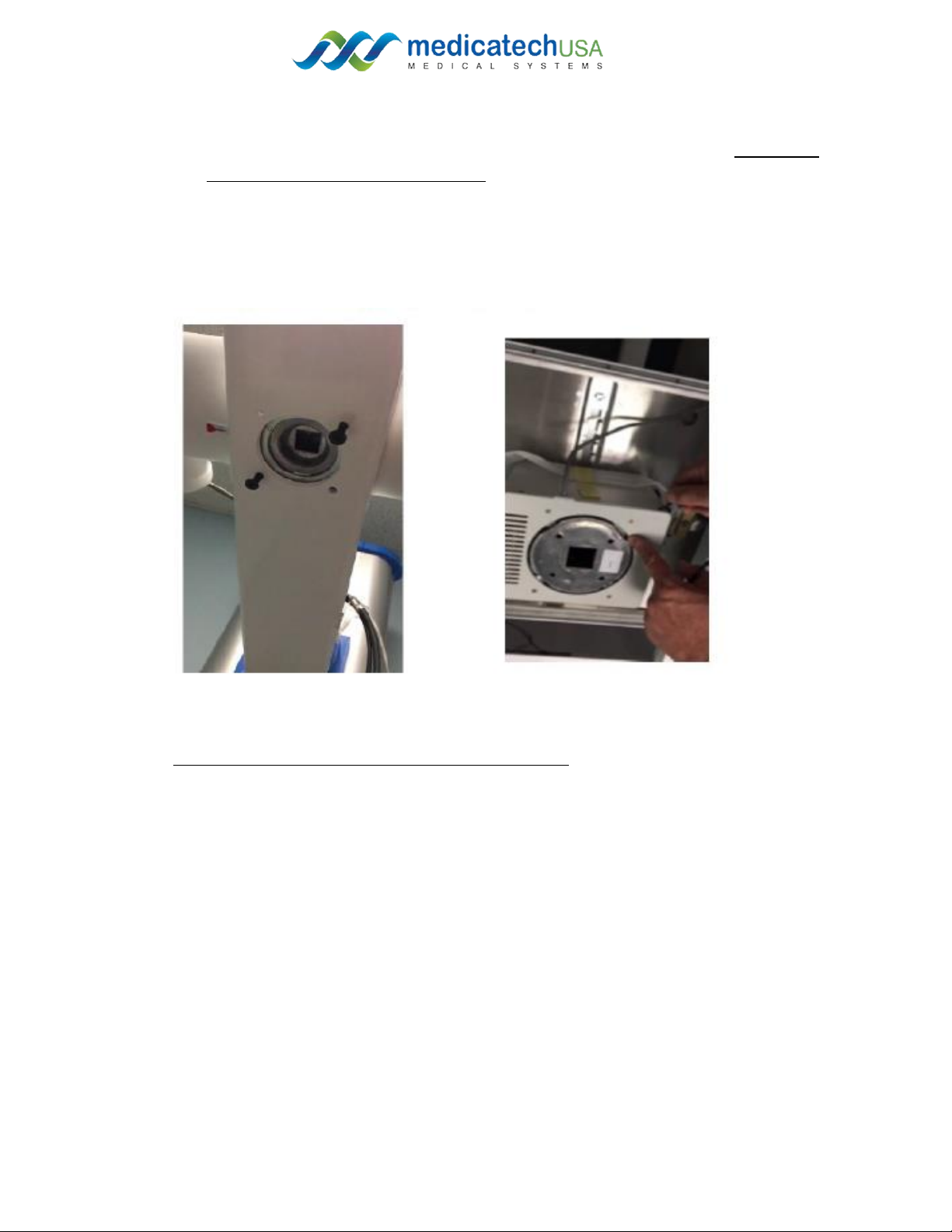
6. Mount the column’s top cap for the tube stand and the chest stand, by the provided M4
screws.
7. Control panel: system movement
7.1. Buttons are the same on both sides
Tube stand (left and right)
Power button
Arm Up and down
Arm Rotation
Table of contents
Other Medicatech Medical Equipment manuals

Popular Medical Equipment manuals by other brands


Cholestech
Cholestech LDX Quick reference guide

Hitachi
Hitachi EUP-LV74 instruction manual

FIOR & GENTZ
FIOR & GENTZ NEURO CLASSIC-SWING Instructions for use

InterTest
InterTest V Series Operation manual

GCE
GCE ECOlite4000 Instructions for use

Cardinal Health
Cardinal Health CHB-AGS Instructions for use manual


