Alpha Communications AlphaRefuge 2100 Series User manual

Copyright© 2011-2018, Alpha Communications®, All Rights Reserved. AWD265 Rev. 2 (08/2019)
AlphaRefuge™ 2100 Series (V3) Area of Refuge and Rescue
Assistance system Installation, Use and Wiring Instructions
Pre-Installation Requirements:
• 120V Power
• Determine Communication:
1. Dedicated analog phone line from POTS, PBX, or Central Oce.
2. VoIP - requires use of Alpha Model ABL-VOIP to connect Master to VoIP phone system.
3. Internal Intercom (no osite calling) - requires Alpha Model 2100-LINESIM.
• Twisted, shielded 22 or 24 AWG wire cabling to connect each Refuge Call Box (RCB) to the
Refuge Command Center (RCC)
• Use 24V 18/2 wire for powering the Emergency Phones from the 24VDC Power Supply.
NOTE: Terminals and markings shown in this manual may not be in the order in which they appear
on the actual equipment. When installing, observe all national and local electrical and building
codes.

2
Installation Steps:
Step 1
Remove the front cover from the SmartRescue and mount the SmartRescue back box to the wall
using suitable mounting screws (not included).
Step 2
Punch out the conduit knockouts for the analog phone line and phone cabling runs.
Step 3
Connect an analog phone line to the outside phone line (Diagram A)
Step 4
Connect the backup battery cable to the battery terminal (battery included). (Diagram A)
DIAGRAM A

3
Step 5
Wire your Refuge Command Center to a 120VAC Power Source
(If your Refuge Command Center comes with a plug-in transformer, simply plug it in, and connect
to 24VDC on RCC board).
• Connect the hot wire of the 120vac to the L screw
• Connect the neutral wire of the 120vac to the N screw
• Connect the ground wire of the 120vac to the ground screw
• Connect one lead of the DC power connection to the –V screw and the other to the +V screw,
polarity is not important.
• Connect the DC power connection to the SmartRescue. The power connection is on the lower
left hand side of the board.

4
Wiring Refuge Call Boxes to Refuge Command Center
Step 6
Wire the Refuge Call Boxes to the Reguge Command Center
Refuge Call Box *Use 22 or 24 AWG 2-pair twisted, shielded cable
between the phones and the SmartRescue. The
maximum communication run is 5,100’
Connecting wire run:
To Refuge Command Center: Insert 4 wires for
each phone as shown below.
To Refuge Call Box: Wire out to a standard
2-pair RJ11 phone jack. Connect this jack to the
5’ cord supplied by Alpha.
Refuge Command Center
The Refuge Call Boxes come with a 5’ cord with
an RJ11 on both ends. If you received a spade
connector, your company requested it. Wire ac-
cording to your company guidelines.
*Shields from the cabling runs (if used) should be
attached to one of the mounting screws on the
SmartRescue housing.

5
Step 7
Mount the front cover back onto the enclosure.
Programming the Refuge Command Center
Step 8
Programming Options for Refuge Command Center
Option 1 (Factory Default)
The Emergency Phones will call directly osite and not stop at the Refuge Command Center.
That phone’s button will light at the Refuge Command Center during the call.
(Keep in Default Mode if site is not manned 24/7 to answer calls onsite)
Option 2
Program the Refuge Command Center to Allow the Emergency Phones to call it rst, then
outside number(s):
(Used when sta are available at certain times to answer calls)
1. Hold down Red Disconnect and Submaster 1 buttons for 5 seconds
2. Release buttons (you will hear a conrmation tone)
3. Press Phone 2 button, then Red button, and then the Phone 1 button
4. Press Submaster 2 button, then Submaster 1 button (you will hear a conrmation tone)
*Note: If you need to restore the Refuge Command Center to Default Mode see page 11.

6
Powering The Refuge Call Boxes
Step 9
Provide power to the Refuge Call Boxes through one of the following 3 options:
Option 1: Powering up to ten Refuge Call Boxes via PWR2410A Power Supply
• Use 1-pair 18 AWG wire for power, maximum distance of 5,100’
• Do NOT wire more than 3 devices per wire run and a maximum of 10 devices per Power
Supply
Option 1:
Transformers (Only if your phone comes with one supplied by Alpha). Requires 120VAC
Option 2:
Powered Directly by Elevator Car. Requires 120VAC.

7
Programming The Refuge Call Boxes
Step 10a
Program appropriate options for each of your Refuge Call Boxes
Option 1: Bypass Refuge Command Center and Dial Directly to Osite Number(s)
• Press Enter to get into program mode
• Press 1, Enter, (Emergency Number), Stop
• If using two emergency numbers: Press 2, Enter, (Emergency Number), Stop
• Repeat for up to 5 total emergency numbers
• To exit programming mode: Press and hold Stop for 2-3 seconds until warble sound
Option 2: Call Refuge Command Center and if No Answer, Dial Osite Number(s)
• Press Enter to get into program mode
• Press 1, Enter, (Emergency Number), Stop
• Press 2, Enter, (same Emergency Number as entered in b.), Stop
• To exit programming mode: Press and hold Stop for 2-3 seconds until warble sound
Step 10b
Program the Location Message
NOTE: This Should ALWAYS be done, unless your call center requests otherwise!!!
• Press Enter to get into program mode
• To turn on message, press 1, 3, Enter, 2
• For no message, press 1, 3, Enter, 0
• Press 6, Record, (wait for beep, speak your message), Stop
• To program frequency of message, press 1, 3, Enter, ___
• 1 = plays message once
• 2 = plays message twice (this is standard conguration)
• 3 = plays message until the called party presses * on their phone
• To exit program mode, press and hold Stop for 2-3 seconds until warble sound

8
System Operation & Testing
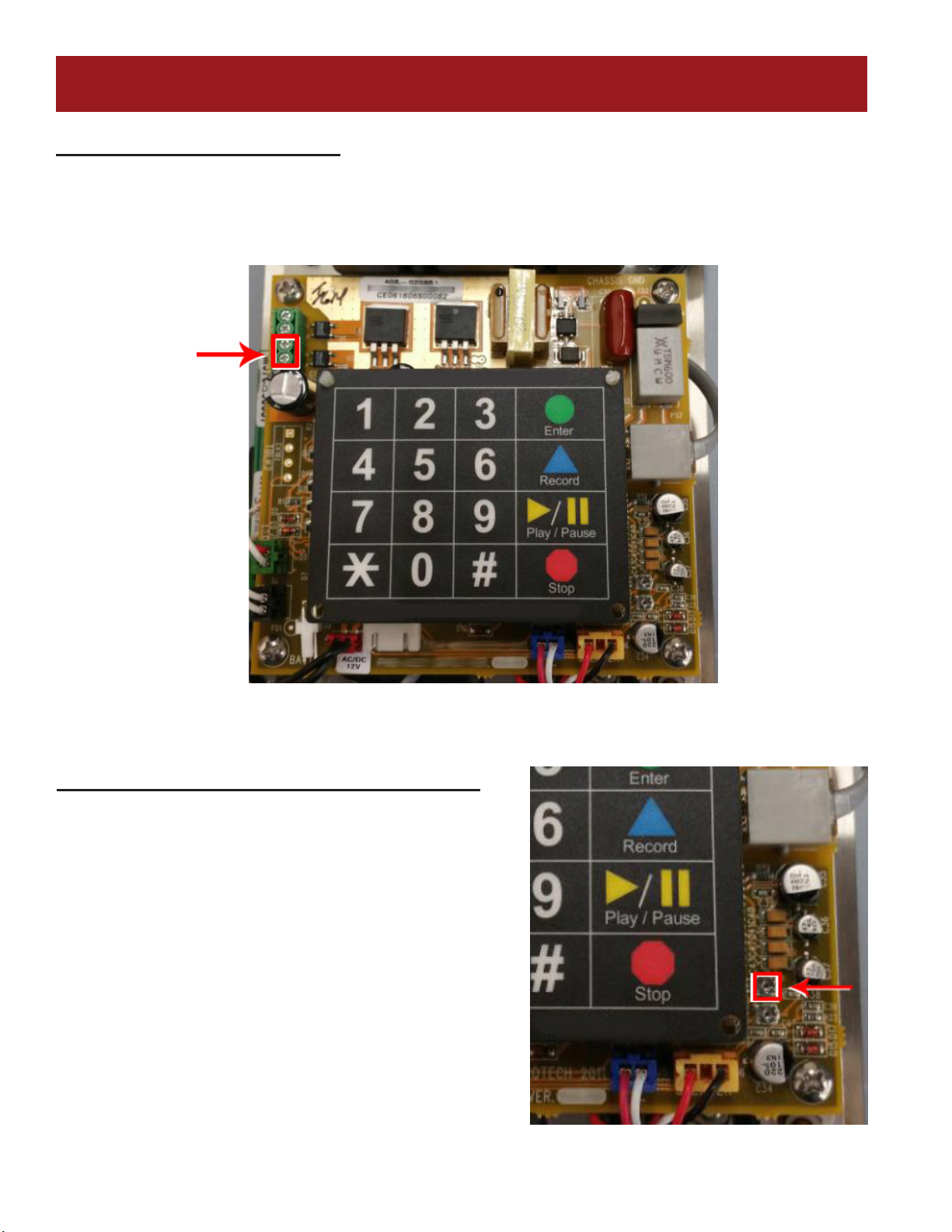
A. Once nished, the following Refuge Command Center LEDs should be lit:
• Power LED, located on bottom edge of the faceplate, will be constant lit green
• Battery LED, also located on bottom edge of the faceplate, will be constant lit.
• Red = Low level charge
• Yellow = Mid level charge
• Green = Full Charge
B. Initiate a Call to an Emergency Phone or Sub-Master from the Refuge Command Center:
• Lift handset on Refuge Command Center
• Press the Talk button for the corresponding Refuge Call Box or Sub-Master you wish
to call into
• The green LED will light next to that button
• You should have two-way communication to that device
• You can place the device on hold by pressing the Talk button a second time
• To resume communication, press the Talk button a third time
• To disconnect, hang up the Refuge Command Center handset
C. Emergency Phone places a call into the Base Station:
• You will hear an alternating audible tone at the Refuge Command Center indicating a
call has been initiated by one of the phones
• The corresponding green LED will light on the Refuge Command Center next to the
phone that placed the call
• Lift the handset and there is two-way communication between the Refuge Command
Center and the Refuge Call Box. The handset can be hung up on the Refuge Command
Center at any time to end the call
D. Refuge Call Box places a call to the Refuge Command Center then an Outside Number, or
Just to an Outside Number:
• You will hear an alternating audible tone at the Refuge Command Center indicating a
call has been initiated by one of the Refuge Call Boxes (if programmed to call outside
line only, no tone)
• The corresponding green LED will light on the Refuge Command Center next to the
Refuge Call Box that placed the call
• If call is not answered at the Refuge Command Center, the Refuge Call Box will hang
up and dial the second number programmed into the phone
• The CO Line LED, located next to the red button, will also be lit indicating that the
outside line is active. Two-way communication can then take place between the outside
line and the Refuge Call Box once the call is answered
• The Refuge Command Center can join the conversation by lifting the handset
• To talk to rescue services only from the Refuge Command Center, place the Refuge
Call Box on hold by pressing the corresponding Talk button. To bring them back into
the conversation, press the Talk button again.
• To disconnect rescue services, press the red button at the top of the Refuge Command
Center faceplate. The Rescue Services LED will go o and leave you communicating
with the Refuge Call Box only.
• Handset on the Refuge Command Center can be hung up at any time to end the call.
If above testing works and voice communication is clear, congratulations,
you have successfully installed the system!

9
System Supervision
NFPA-Required for Area of Refuge Systems, not Required for Elevator Industry
NFPA-2016
24.10.4 - All pathways between a remote area of refuge station and the central control point shall be
monitored for integrity.
24.13.4 Power Supplies: All control units shall meet the power supply requirements of section 10.6s
10.6.9 Monitoring Integrity of Power Supplies
10.6.9.1 Unless otherwise permitted or required by 10.6.9.1.3 and 10.6.9.1.6 all primary and secondary
power supplies shall be monitored for the presence of voltage at the point of connection to the system.
10.6.9.1.1 Failure of either the primary or secondary power supply shall result in a trouble signal in
accordance with section 10.14
10.6.7.2.1 The secondary power supply (battery back up) shall have sucient capacity to operate the
system under quiescent load (system operating in a nonalarm condition) for a minimum of 24 hours and,
at the end of that period, shall be capable of operating all alarm notication appliances used for
evacuation or to direct aid to the location of an emergency for 5 minutes.
Appendix

10
Phone Line Supervision
Alpha Refuge Call Boxes have a built-in Line Check Feature. The station constantly looks for a
phone line. When a phone line is not detected it will trigger the onboard relay. Connect the relay to
an alarm device for notication.
Appendix
Adjusting Volume on Refuge Call Boxes
• Locate the silver VR1 port on the bottom right
corner of the Refuge Call Box board
• Using a ne Philips Head screwdriver, turn the
VR1 clockwise to increase the volume and
counterclockwise to decrease the volume.

11
Refuge Call Box System Activation Relay
When an Emergency phone has been activated,
this relay changes state and can be connected to an
alarm panel, strobe, or other notication means.
Appendix
Restoring Refuge Command Center Factory Default Settings
• Hold down Red Disconnect and Submaster 1 buttons for 5 seconds
• Release buttons (you will hear a conrmation tone)
• Press Phone 2 button, then Red button, then Submaster 2 button, and then the Phone 5 button
• Press Submaster 2 button, then Submaster 1 button (you will hear a conrmation tone)

12
Troubleshooting
PROBLEM POSSIBLE CAUSE & SOLUTION
Power LED is not illumi-
nated:
• Check to make sure the transformer is connected to a good 120V power
source. If 24V powered, check the power supply.
• Make sure power connection on the circuit board is secure.
Battery LED is not il-
luminated or always
shows red:
• Battery has not charged for long enough. Wait 18 hours for the battery to
trickle charge. When fully charged it will have 19v.
• Battery plug is not connected to circuit board. Verify connection.
• Battery is worn. It is recommended to replace every 2 years.
LEDs on Refuge Call Box
ash when button is
pressed:
• Verify the phone line is working and is connected properly.
• Verify dial tone is present at the Refuge Command Center.
Submaster and Phone
LEDs blinking on Refuge
Command Center:
• Verify power is applied and the backup battery is connected properly to the
Refuge Command Center board.
Refuge Command Cen-
ter LEDs stay on:
• Wires may be crossed. Verify wiring from the Refuge Command Center to the
Refuge Call Boxes is correct.
Two-way communica-
tion from Refuge Call
Box is poor:
• There is likely feedback on the line. Adjust the VR1 and VR2.
• Verify wiring is not spliced onto the phone line cord.
Refuge Command Cen-
ter will not dial phones:
• Verify wires are connected properly from the Refuge Command Center to the
Refuge Call Box(es).
Refuge Command Cen-
ter will dial Refuge Call
Boxes, but Call Boxes
will not dial Command
Center:
• No outside phone line connected to Refuge Command Center.
• Phone line connected does not have working 24v to 52v.
• Line connected has voltage but does not have working dial tone.
• Plug analog phone into phone line and place a call out to verify line.
No sound or tone on
Command Center hand-
set:
• Verify 24v power is connected to the Command Center base.
Dial tone present on
Command Center hand-
set and phone is not
calling out:
• There should not be a dial tone on the Command Center handset.
• Wire pairs are out of order. Verify wire pairs are connected to the correct pins.
• Wires are shorted and need to be replaced.
Appendix
ALPHA COMMUNICATIONS® • 42 Central Drive • Farmingdale NY 11735-1202
TOLL-FREE TECHNICAL LINE 1-800-666-4800 • Phone: 631-777-5500 • Fax: 631-777-5599

13

14

15

16

17
RCB2100SF Flush Mount St. Steel
Remote Call Box Station

18
RCB2100SF Flush Mount St. Steel
Remote Call Box Station
Table of contents
Other Alpha Communications Emergency Phone manuals
Popular Emergency Phone manuals by other brands

LogicMark
LogicMark Freedom Alert 35911 Installation & operation instructions

sabya
sabya Grey bell instruction manual

TeleAlarm
TeleAlarm Carephone 62 Quick user guide

Soundoff Signal
Soundoff Signal Armada A300 quick start guide

Talkaphone
Talkaphone ETP-100E Installation & operation manual

AT&T
AT&T SPAREONE user guide