Mediso Nucline SPIRIT DH-V User manual
Nucline
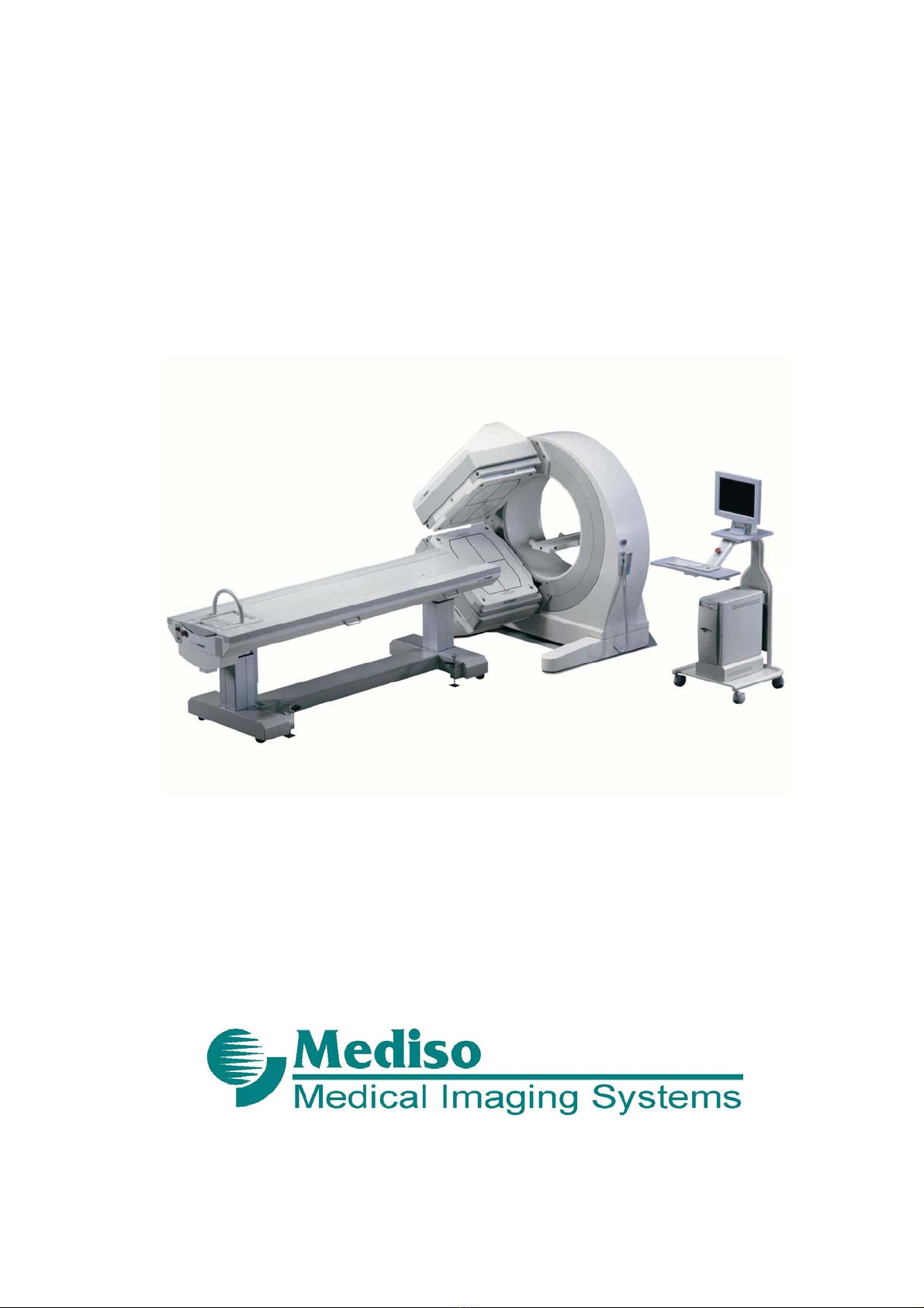
TM SPIRIT DH-V
DUAL - HEAD SPECT AND WHOLE BODY
DIGITAL GAMMA CAMERA
Service Manual
Revision 1.02

Acquisition software release: v.7.03
The information and drawings set forth in this manual are the property of Mediso Ltd. No part
of this document may be copied without the prior consent of Mediso Ltd.
Manufacturer reserves the right to revise or update the contents of this manual due to
modifications or improvements in the design of the equipment without obligation to notify any
person or organization of such changes.
Nucline
is a registered trademark of Mediso Ltd.
Other brand or product names are trademarks or registered trademarks of their respective
holders.
Mediso Ltd. - Medical Imaging Systems
Address: H-1022 Budapest, Alsótörökvész út 14. HUNGARY
Phone: +36-1 3993030
Fax: +36-1 3993040
E-Mail: info@Mediso.hu

Revision 1.02 3/216
Disclaimer
Mediso Ltd. and its official representatives may not be held responsible for personal injury or
damage of any kind, expressed or implied, caused by, or emerging out of the use of this
equipment, if equipment is not operated in adherence to operating and maintenance
procedures set forth in this manual.
Users exchanging files and diskettes should beware of the risk of computer viruses. Damage
caused by user provided programs, scripts, or computer viruses are NOT warranted by
Mediso Ltd.
Warning
Electrical
Failure to provide an adequate earth ground circuit can result in a shock
hazard which can cause serious personal injury.
Only properly trained personnel should be permitted access to any internal
part of the equipment. Live electrical terminals and components inside electronics cabinets
can present a shock hazard and can cause serious or fatal injury.
Maintenance and service routines beyond those mentioned in this manual must be referred
to service personnel authorized by the manufacturer. In the absence of appropriate
instructions in this manual do not attempt to make service work on the equipment.
When this equipment is interconnected with other electrical appliances in its normal
operation, it is important, that these other appliances also be provided with adequate
grounding protection. Faults occurring in any interconnected appliance can degrade the
safety of this product.
Mechanical
All moveable assemblies and supporting structures should be operated with care and
routinely inspected. Any collision which could damage the equipment, worn components,
unusual noises or difficulties in operation should be reported to the manufacturer's office
immediately.
Radiation
This equipment does not generate any hazardous radiation. When using radioactive isotopes
or compounds, safe and proper handling techniques should always be observed. If
radioactive contamination occurs, use the decontamination agent and method as described
in your site protocol to clean the outside of the equipment.

Nucline
SPIRIT DH-V Service Manual
4/216 05/05/2006
ECN Rev. Date Description Pages Approved
0000306 1.01 2006.05.05. New document all
0000534 1.02 2006.07.12 DR interface panel
changing 77 - 85

Revision 1.02 5/216
Table of contents
Disclaimer .............................................................................................................................................. 3
Warning .................................................................................................................................................. 3
Electrical .............................................................................................................................................. 3
Mechanical........................................................................................................................................... 3
Radiation.............................................................................................................................................. 3
Table of contents ...................................................................................................... 5
Introduction ............................................................................................................... 9
Scope of manual ..................................................................................................... 10
Text Conventions Used in this Manual ................................................................. 11
Chapter 1. Safety and Regulatory Information................................................... 12
1.1 General Safety........................................................................................................................... 12
1.1.1 Electrical Safety................................................................................................................... 13
1.1.2 Mechanical Safety ...............................................................................................................15
1.1.3 Radiation ............................................................................................................................. 15
1.2 IEC Symbols Used.................................................................................................................... 16
1.3 Safety Devices .......................................................................................................................... 17
1.3.1 Emergency Stop Button ...................................................................................................... 18
1.3.2 Preventing Collisions...........................................................................................................18
1.4 Patient Safety and Emergency Egress................................................................................... 20
1.4.1 Patient Handling .................................................................................................................. 20
1.4.2 Patient Positioning............................................................................................................... 20
1.4.3 Emergency Egress .............................................................................................................. 21
1.4.4 Power Failure Procedure..................................................................................................... 21
1.4.5 When Electrical Power is Restored..................................................................................... 21
1.5 Data Safety ................................................................................................................................ 22
1.5.1 General................................................................................................................................ 22
1.5.2 Connectivity ......................................................................................................................... 22
1.6 Safe Operation Guidelines.......................................................................................................22
1.7 Safety Labels............................................................................................................................. 23
1.8 Regulatory Information ............................................................................................................ 24
1.8.1 Standard Compliance.......................................................................................................... 24
1.8.2 USA Regulations .................................................................................................................25
Other manuals for Nucline SPIRIT DH-V
1
Table of contents
Other Mediso Medical Equipment manuals

Popular Medical Equipment manuals by other brands


Getinge
Getinge Arjohuntleigh Nimbus 3 Professional Instructions for use

Mettler Electronics
Mettler Electronics Sonicator 730 Maintenance manual

Pressalit Care
Pressalit Care R1100 Mounting instruction

Denas MS
Denas MS DENAS-T operating manual

bort medical
bort medical ActiveColor quick guide

AccuVein
AccuVein AV400 user manual


