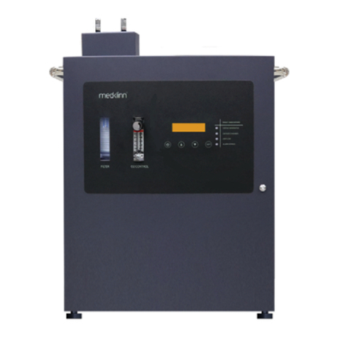
MedKlinn PRO AS750D User manual

PRO AS750D
USER MANUAL

1. Safety Precautions
2. Device Identication
3. System Overview
4. Control Panel Identication
5. Getting Started
- Display Screen Menu
- Changing the Settings
- Fault Indicator on the control panel
- Controlling the Active Oxygen emission rate
- Installation of device
- Installation of nozzle
6. Basic Maintenance
1
3
6
7
9
13
22
26
27
28
30
TABLE OF CONTENT

1
1. Do not use the device if the power cable or plug is damaged.
2. Do not insert any sharp or pointed object through the ventilation holes of the device.
3. Do not let unauthorized personnel to play with the device.
4. Do not immerse the device in water, or allow water or any uids to enter through the ventilation holes.
5. When removing the power plug, always hold the plug and never pull the cable.
6. Do not remove the power plug when your hands are wet.
7. Remove the power plug from the wall socket before cleaning the device.
8. Do not modify, disassemble or repair this device without proper training and consulting the manual beforehand. Opening
the device or tampering with it in any way without proper training will cause the Warranty to become void. If you encounter
any problem with the device, please contact the nearest authorized Medklinn Service Centre.
9. Do not replace the electric plug or cut the power cable. Replacing the plug or cutting the power cable in any way will
immediately cause the warranty to become void. Any subsequent fault in the operation of the device will not be covered by
the Warranty, and repair and maintenance service will be chargeable.
10. If the power cable is damaged, contact an authorized Medklinn Service Centre for repairs immediately.
11. Do not wipe the device with benzene or paint thinner.
FOR FURTHER ASSISTANCE, PLEASE CALL OUR CUSTOMER SERVICE.
SAFETY PRECAUTIONS
WARNINGS - To reduce the risk of electrical shock, re or injury:

2
NOTE – Radio, TV or sensitive equipment interference:
If the device should cause interference to radio, television reception or any sensitive equipment, try to correct the interference
by one or more of the following measures:
- Reorient or relocate the receiving antenna.
- Increase the distance between the device and radio/TV receiver/sensitive equipment.
- Connect the equipment into an outlet on a circuit dierent from that to which the receiver is connected.
- Consult the dealer or an experienced radio/TV technician for help.
Cautions during operation:
1. Place the device at least six feet from radio, television or electronic equipment. This is to minimize the possibility of
interference with the equipment or the remote controller.
2. Do not cover the device in any way at all, particularly the ventilation holes. Doing so will cause excessive heat build-up and
may result in a re and irreparable damage to the device.
3. Ensure free ow of air around the device.
4. Avoid locations where the device is exposed to condensation due to rapid and drastic temperature uctuations. The
device should only be used in temperatures between 10º-35ºC.
5. Eective cleaning by Active Oxygen requires adequate air exchange as they are created from oxygen. Regular air exchange
will take place if the door or window is opened occasionally.
6. Do not use the device in small enclosed spaces where there is no or poor air circulation e.g. in wardrobes, closets or
pantries.
7. Active Oxygen is very reactive, and there may be some loss of paint from poorly painted surfaces. To minimize this, do not
place the nozzles directly against walls or other painted surfaces, and leave a space of at least two feet from these surfaces.
8. It is NOT recommended to place the nozzle directly too close to pets.

3
DEVICE IDENTIFICATION
Medklinn PRO AS750D (Front View)
Functional parts
O2 Control
Filter
Reservoir
Active Oxygen
Outlet
Control Panel
Door
Door Lock
Controls the amount of oxygen
owing into the device’s ozone
module
Filters the air supply
Collects any liquid formed
from air condensation
Outlet for the generated Active
Oxygen
Controls/Monitors the entire
system
Door of the device
Locks the device’s door
Active Oxygen Outlet
Reservoir
Door Lock
Door
Filter
O2 Control
Control Panel

6
4
Compressor
Medklinn PRO AS750D
(Inner Compartment View)
Functional parts
Compressor
Oxygen
Tower
Power Supply
Fan
HVPS
Ozone Module
Pushes air into the device
Increases oxygen purity in the
air supply
Supplies power to the fan
Cools internal compartment
temperature
Supplies power to the ozone
module
Generates the Active Oxygen
Power
Supply
Ozone Module
HVPS
Oxygen
Tower
Fan
DEVICE IDENTIFICATION

8
5
Medklinn PRO AS750D
(Bottom View)
Medklinn PRO AS750D
(Top View)
Functional parts
Ozone Sensor
Port
Air Ventilation
Holes
Leveling Feet
Port for the ozone sensor cable
(Optional accessory)
Holes for air to ow in/out of
the inner compartment
Adjustable feet to control
height of device on a surface
Ozone Sensor
Port
Leveling Feet
Fan Filter Air Ventilation
Holes
DEVICE IDENTIFICATION
Fan Filter Filters dust from entering the
inner compartment

6
SYSTEM OVERVIEW
Medklinn PRO AS750D converts supplied oxygen (O2) into Active Oxygen (O3 and O-). The Active Oxygen generated is nature’s
most powerful sterilizing force, killing up to 99% bacteria, viruses, allergens, moulds, and other pollutants from both air and
surfaces in any indoor spaces.
When the Medklinn PRO AS750D operates, the air is taken in by the compressor through the air inlet into the HEPA lter. This
air is forced through a ne mesh lter that traps pollutants before passing into the oxygen tower, which compresses the air
and removes nitrogen from it, thus increases the purity of oxygen (O2) up to 90%.
The concentrated oxygen (O2) is nally supplied to the ozone module which breaks it down to its Active Oxygen components
(O3 and O-) with the use of electricity. It is then released into the environment through the Active Oxygen outlet.

7
Functional parts
Display Screen
Power Indicator
Power Button
Displays information status of
the device
Shows that the device is
ON/OFF
To switch the device ON/OFF
and works as BACK button in
the menus
SET
OZONE GENERATOR
FAULT INDICATORS
OXYGEN CHAMBER
AIR FLOW
ALARM BYPASS
Display Screen
Power
Button
Power
Indicator
Up
Button
Down
Button
Set
Button
Up / Down
Button
Set Button
To scroll up and down in the
menu
To select options in the menus
CONTROL PANEL IDENTIFICATION

8
Ozone
Generator
Oxygen
Chamber
Points to a problem with the
ozone generator
Points to a problem with the
oxygen chamber
Air Flow Points to a problem with the
air ow
Alarm Bypass Shows that an alarm bypass
was done and the device will
continue running for another
30 days before shutting down
Fault indicators
SET
OZONE GENERATOR
FAULT INDICATORS
OXYGEN CHAMBER
AIR FLOW
ALARM BYPASS
Display Screen
Power
Button
Power
Indicator
Up
Button
Down
Button
Set
Button
CONTROL PANEL IDENTIFICATION

9
GETTING STARTED
1. Plug the power cord into the connector of the device and 110V-240V AC power outlet.
NOTE: Proper grounding for international plugs:
For safety precaution, international plugs must have proper grounding wire connected to the device.
2. Press the Power Button on the Control Panel to switch on the device
3. The Power Indicator and Display Screen will light up when the device is switched on.
4. The device’s information status will be displayed one after another repeatedly on the Display Screen.
1. CLOCK
Displays the current time on the device (hh:mm:ss).
Display screen menu
Clock
08:00:00
2. (a) MODE: NORMAL
Shows that the device is in standard operation mode. MODE: NORMAL

12
10
(b) MODE: TEMPORARY
Shows that the device has an issue to be addressed and has 30
days remaining of operating time before it shuts down. Make a
call to the nearest Medklinn’s service center to address the issue.
MODE: TEMPORARY
REMAIN: 30 days
(c) MODE: STOPPED
Shows that the device has stopped operating. Make a call to the
nearest Medklinn’s service center to address the issue.
MODE: STOPPED
Call for service
3. P1
Shows the setting of Program 1. It includes the start time, end
time, and the time interval of the device alternating from on to
o for that duration.
P1 8:00 - 12:00
10 ON, 30 OFF (MIN)
start time end time
time interval

13
11
4. P2
Shows the setting of Program 2. It includes the start time, end
time and shows that this current program is being disabled.
5. P3
Shows the setting of Program 3. It includes the start time, end
time and shows that this current program is being disabled.
6. P24h
Shows the setting of Program 24h. It includes the start time, end
time and the time interval of the device alternating from on to o
for the entire 24 hour period.
P2 12:00 - 14:00
Disabled
P3 15:00 - 17:00
Disabled
P24h 00:00 - 24:00
10 ON, 10 OFF (MIN)
7. FLOW
Shows the ow rate of oxygen into the ozone module. FLOW
1.5 LPM

12
8. O3 LVL at ROOM1 (Optional. Activated when ozone sensor is
installed)
Shows the ozone level detected by ozone sensor 1.
9. O3 LVL at ROOM2 (Optional. Activated when ozone sensor is
installed)
Shows the ozone level detected by ozone sensor 2.
10. O3 LVL at ROOM3 (Optional. Activated when ozone sensor is
installed)
Shows the ozone level detected by ozone sensor 3.
O3 LVL at ROOM1
0.00PPM
0.00PPM
O3 LVL at ROOM2
0.00PPM
O3 LVL at ROOM3
11. The information above will be displayed one at a time in a 5 second rotation (depending on the administrator
setting).
12. The information on the Display Screen can also be toggled through the Up/Down buttons on the Control Panel.

13
Changing the settings
1. Switch on the device by pressing Power on the Control Panel.
2. Wait until the information on the Display Screen is shown.
3. Press Set to enter into the main menu. Except the Display Screen, the other components stop operating while in
this mode.
(i) Changing the clock time
4. Press Set on Clock Setting.
5. Press Up to change hour and Down to change minutes. The
time format is in 24-hour clock mode.
6. Press Set to conrm on the time change. After 3 seconds, the
display Setting Accepted will be shown.
7. Press any key to acknowledge the change.
Clock Setting
08:00:00
Edit Value
Setting Accepted
Press any key…

16
14
(ii) Changing the operation time
Program 24h
8. From step 3, press Down to go onto the next option in the
main menu. The display Program Setting will be shown.
12. Press Set to congure settings of Program 24h.
10. To set a single operation time for the entire 24 hours, press
Down until Program 24h is shown and follow steps 12 - 16 only.
9. Press Set to change the Program Setting.
11. To set multiple operation times, press Down until Program 1,
2 and/or 3 are shown. Follow steps 17 – 31 to set up Program 1.
Program Setting
Program 24h
13. Press Set to select ON time. Edit Program 24h
ON Time

15
14. Press Up/Down to toggle the time interval wanted.
Disable Program
Time 6
Time 1 Time 2 Time 3 Time 4 Time 5
Time 7 Time 8 Time 9 Time 10 Time 11
Time 15 Time 16 Time 17Time 12 Time 13 Time 14
Time 21 Time 22 Time 23Time 18 Time 19 Time 20
Time 25 ON ALWAYSTime 24
Disable 10minON,
10minOFF
10minON,
20minOFF
10minON,
30minOFF
10minON,
40minOFF
10minON,
50minOFF
20minON,
20minOFF
20minON,
30minOFF
20minON,
40minOFF
20minON,
50minOFF
30minON,
10minOFF
30minON,
30minOFF
30minON,
40minOFF
30minON,
50minOFF
40minON,
10minOFF
40minON,
20minOFF
40minON,
40minOFF
20minON,
10minOFF
30minON,
20minOFF
40minON,
30minOFF
40minON,
50minOFF
50minON,
10minOFF
50minON,
20minOFF
50minON,
30minOFF
50minON,
40minOFF
50minON,
50minOFF
ALL TIME ON

16
15. Press Set to select. There will be an asterisk beside the values
to show that this particular time is selected.
16. Press Power twice to go back to main menu.
*10min ON,
30min OFF
Program 1
Edit Program 1
ON Time
Program 1
17. Press Set to congure settings of Program 1.
18. Press Set to select ON time.

17
19. Press Up/Down to toggle the time interval wanted.
Disable Program
Time 6
Time 1 Time 2 Time 3 Time 4 Time 5
Time 7 Time 8 Time 9 Time 10 Time 11
Time 15 Time 16 Time 17Time 12 Time 13 Time 14
Time 21 Time 22 Time 23Time 18 Time 19 Time 20
Time 25 ON ALWAYSTime 24
Disable 10minON,
10minOFF
10minON,
20minOFF
10minON,
30minOFF
10minON,
40minOFF
10minON,
50minOFF
20minON,
20minOFF
20minON,
30minOFF
20minON,
40minOFF
20minON,
50minOFF
30minON,
10minOFF
30minON,
30minOFF
30minON,
40minOFF
30minON,
50minOFF
40minON,
10minOFF
40minON,
20minOFF
40minON,
40minOFF
20minON,
10minOFF
30minON,
20minOFF
40minON,
30minOFF
40minON,
50minOFF
50minON,
10minOFF
50minON,
20minOFF
50minON,
30minOFF
50minON,
40minOFF
50minON,
50minOFF
ALL TIME ON

20. Press Set to select. There will be an asterisk beside the values
to show that this particular time is selected.
21. Press Power to go back to the previous menu.
*10min ON,
30min OFF
Edit Program 1
Start Time
Edit Value
08:00:00
22. Press Down and then Set to enter Start Time conguration.
23. Press Up to change hour and Down to change minutes.
Setting Accepted
Press any key…
24. Press Set to conrm on the start time. After 3 seconds, the
display Setting Accepted will be shown.
25. Press any key to acknowledge the change.
Edit Program 1
End Time
26. Press Down and then press Set to enter End Time
conguration.
18
Table of contents
Other MedKlinn Laboratory Equipment manuals
Popular Laboratory Equipment manuals by other brands
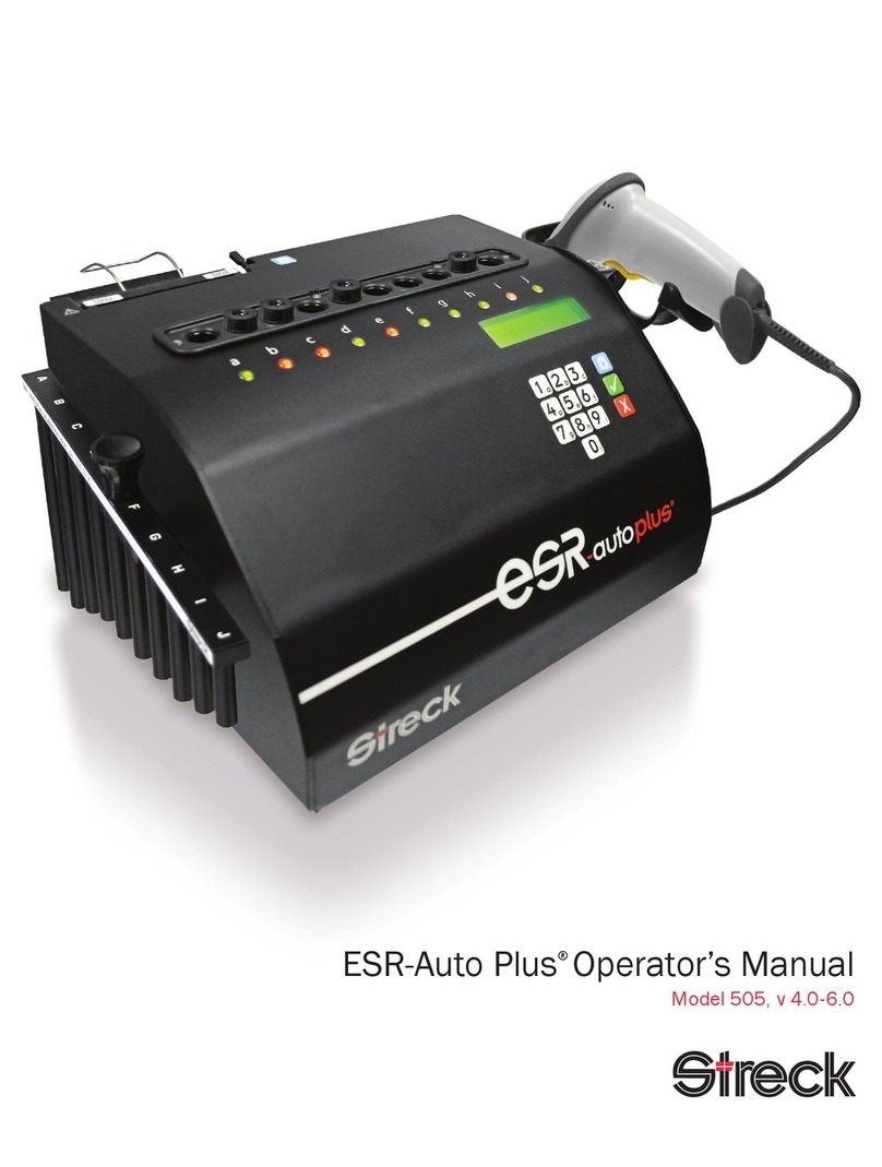
Streck
Streck ESR-Auto Plus 505 Operator's manual
HTL
HTL CLINIPET+ manual
DiaSys
DiaSys SSE-006 Operator's manual

Thermoline Scientific Equipment
Thermoline Scientific Equipment TFB-1 operating instructions

Ortho-Clinical Diagnostics
Ortho-Clinical Diagnostics MTS Centrifuge 5150-60 Service manual
Soilmoisture Equipment
Soilmoisture Equipment PR16 quick start guide
