Medora SolarBee SB1250PWc User manual

www.medoraco.com
• 866 - 437 - 8076 •
O&M_SB1250PWc_10239_20191105
SB1250PWc Owner's Manual
Table of Contents
About Medora Corporation
Medora Corporation combines knowledge and experience from across the water quality spectrum to help
solve real-world problems. Whether in Lakes, Stormwater Retention Ponds, Raw Drinking-Source Reservoirs,
Water Treatment Plants, Potable Storage Tanks, or Wastewater Treatment Processes, Medora Corporation
equipment continues to be at the forefront as the #1 world leader for in-situ water body treatment.
© 2019 Medora Corporation | www.medoraco.com | 866 - 437 - 8076 | [email protected]
Table of Contents
10014_20191001
SB1250PWc Owner's Manual
Safety 1
Operation 4
Features 5
Maintenance 13
Electrical 18
Technical Specifications 21
Troubleshooting 22
Parts Diagram 25
Dimension Drawing 26
Warranty 27
Customer Service 28
O&M_SB1250PWc_10239_20191105

Carefully read safety information when you see
any safety symbols.
Be sure you have read all installation, operation, maintenance and safety instructions
before you install, service or begin to operate this unit.
Accidents occur every year because of careless use of industrial equipment. You can avoid
hazards by following these safety instructions, and applying some ordinary common sense
when operating or servicing this unit.
Keep in mind that full operator attention and alertness are required when operating or
servicing this unit.
USE COMMON SENSE!! Most accidents can be avoided by using common sense and
concentration on the job being done.
© 2019 Medora Corporation | www.medoraco.com | 866 - 437 - 8076 | [email protected]
Safety
Safety
1949_10036_20191001 O&M_SB1250PWc_10239_20191105 - 1
IMPORTANT!!!
Follow all federal and state laws in regards
to safety regulations of working at heights,
conned spaces, rescue, etc. as required by
the U.S. Department of Labor, Occupational
Safety and Health Administration. Use
necessary PPE when placing and servicing
this unit.
Identify all possible hazards. Determine what
safeguards are needed and implement them.
Only you, the user, understand your product
and system characteristics fully. The ultimate
responsibility for safety is with you. Your
safety ultimately rests in your hands. Do
your part and you will enjoy safe, trouble free
operation for years to come. This instruction
manual is not intended to include a compre-
hensive listing of all details for all procedures
required for placement, operation and mainte-
nance. If you have a question about a proce-
dure or are uncertain about any detail, Do Not
Proceed. Please contact GridBee Customer
Service at 866-437-8076 to speak to a repre-
sentative.
ELECTRICAL HAZARD
WARNING: THIS EQUIPMENT CONTAINS HIGH
VOLTAGE! ELECTRICAL SHOCK CAN CAUSE
SERIOUS OR FATAL INJURY. ONLY QUALIFIED
PERSONNEL SHOULD ATTEMPT PLACEMENT,
OPERATION AND MAINTENANCE OF
ELECTRICAL EQUIPMENT. REMOVE ALL
SOURCES OF ELECTRICAL POWER BEFORE
PERFORMING ANY SERVICE WORK TO THE
MACHINE. USE PROPER LOCKOUT TAGOUT
(LOTO) PROCEDURES TO ENSURE A SAFE
WORK ENVIRONMENT.
Rotating Hazard
CAUTION: KEEP BODY APPENANDAGES OR
LOOSE CLOTHING AWAY FROM EQUIPMENT
WHILE OPERATING. ENSURE EQUIPMENT IS
OFF BEFORE ATTEMPTING SERVICE.
Crush Hazard
WARNING: DO NOT REMOVE ANY FLOAT
ASSEMBLY BOLTS OR PINS WHILE
EQUIPMENT IS FLOATING IN WATER.
EQUIPMENT MUST BE SECURELY
SUPPORTED BEFORE PERFORMING
SERVICE.
Laceration Hazard
CAUTION: EDGES MAY BE SHARP AND
CAUSE LACERATION IF PROPER CARE IS
NOT USED.
Entanglement Hazard
WARNING: ENSURE THAT PERSONNEL ARE
CLEAR OF THE ELECTRIC CORD AND CHAIN
TO AVOID ENTANGLEMENT.
Thin Ice Hazard
WARNING: ICE SURROUNDING MACHINE
MAY NOT SUPPORT WEIGHT, KEEP CLEAR OF
THIN ICE.
© 2019 Medora Corporation | www.medoraco.com | 866 - 437 - 8076 | [email protected]
Safety
Safety
1949_10036_20191001 O&M_SB1250PWc_10239_20191105 - 2

Permit-Required
Conned Spaces
A conned space has limited openings for
entry or exit, is large enough for entering and
working, and is not designed for continuous
worker occupancy. Conned spaces include
underground reservoirs, ground storage tanks,
elevated tanks, silos, manholes, and pipelines.
Conned Space Tips
• Do not enter permit-required conned spaces
without being trained and without having a
permit to enter.
• Review, understand and follow employer’s
procedures before entering permit-required
conned spaces and know how and when
to exit.
• Before entry, identify any physical hazards.
• Before and during entry, test and monitor for
oxygen content, ammability, toxicity or
explosive hazards as necessary.
• Use fall protection, rescue, air monitoring,
ventilation, lighting and communication
equipment according to entry procedures.
• Maintain contact at all times with a trained
attendant either visually, via phone, or by
two-way radio. This monitoring system
enables the attendant and entry supervisor
to order you to evacuate and to alert
appropriately trained rescue personnel to
rescue entrants when needed.
Refer to 29 CFR 1910.146 for complete
regulations set by OSHA. Refer to your state's
regulations if your state established and operates
their own safety and health programs approved
by OSHA.
Protect Yourself
Medora Corporation insists that you comply with
all relative OSHA and local regulations while
installing and performing any maintenance to the
mixer circulation equipment.
Key OSHA Compliance Standards that must
be followed (and not limited to) are:
• 1910.146 Permit-required conned spaces
• 1910.147 Lockout/Tagout
• 1926.500 Fall Protection
Fall Protection Tips
• Identify all potential tripping and fall hazards
before work starts.
• Look for fall hazards such as unprotected
oor openings/edges, shafts, open hatches,
stairwells, and roof openings/edges.
• Inspect fall protection and rescue equipment
for defects before use.
• Select, wear, and use fall protection and
rescue equipment appropriate for the task.
• Secure and stabilize all ladders before
climbing.
• Never stand on the top rung/step of a ladder.
• Use handrails when you go up or down stairs.
• Practice good housekeeping. Keep cords,
welding leads and air hoses out of walkways
or adjacent work areas.
Refer to 29 CFR 1926.500 for complete
regulations set by OSHA. Refer to your state's
regulations if your state established and operates
their own safety and health programs approved by
OSHA.
Lockout Tagout
When the On/Off switch is in the "ON" position,
the mixer may start up at any time if not already
operating. The mixer's On/Off switch can be
locked out by placing a pad lock thru the door latch
of the controller after the switch has been turned
to the "OFF" position. The On/Off switch is to be
used as the emergency stop.
© 2019 Medora Corporation | www.medoraco.com | 866 - 437 - 8076 | [email protected]
Safety
Safety
1949_10036_20191001 O&M_SB1250PWc_10239_20191105 - 3
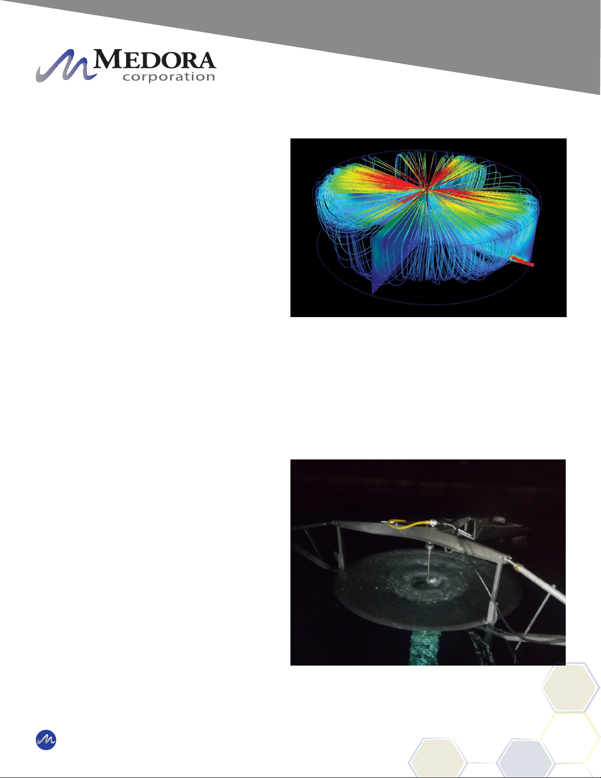
The SolarBee is designed to circulate water
by bringing water from below and sending it
out across the top in a thin layer causing a
mixing effect. The laminar layer ows outward
radially, in diverging “stream lines” from the
distribution dish. As it does, vertical ow is
induced in between the water being drawn
below and the water above. At the level of the
ow intake, water is drawn from all corners of
the tank. As this lower layer of uid makes its
way inward with converging streamlines to the
SolarBee, the water is forced upward, toward
the surface, providing gentle mixing and
de-stratication.
The SolarBee obtains all the energy it needs
from the sun. Its solar panels provide power
to the onboard battery which energizes the
drive system’s controls and motor. Excess
solar energy is stored during the day and
used during the night allowing the SolarBee
to operate during the night without being
connected to the grid.
During operation, a visible ow can be
observed coming off the distributor dish
and spreading outward. The impeller of the
SolarBee is designed to operate at full speed
when there is sufcient sunlight and battery
charge. The rpms may drop down some
during the later night and early morning when
the battery uses up its charge after a longer
period of overcast days. In severe sunlight
limited conditions, the machine may slow
down or stop temporarily to protect the battery
from damage.
SolarBee Series Flow Model
Flow Coming Off Distribution Dish
© 2019 Medora Corporation | www.medoraco.com | 866 - 437 - 8076 | [email protected]
Operation
Operation
SB Series
10199_20191008 O&M_SB1250PWc_10239_20191105 - 4

The SolarBee with technology includes new
features which enhance its performance
through more efcient and durable components,
improved operation monitoring capablilities, easy
component access, and a robust frame structure.
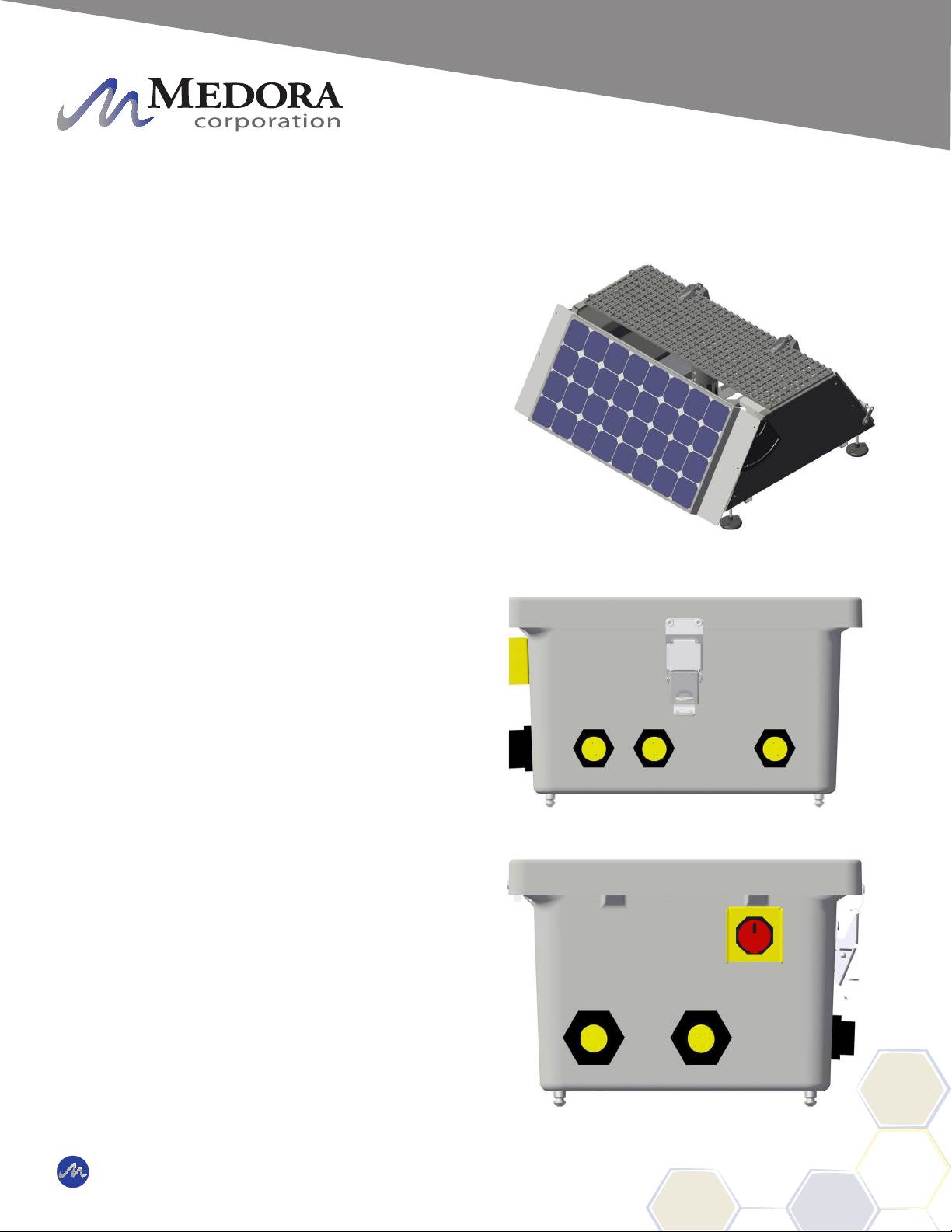
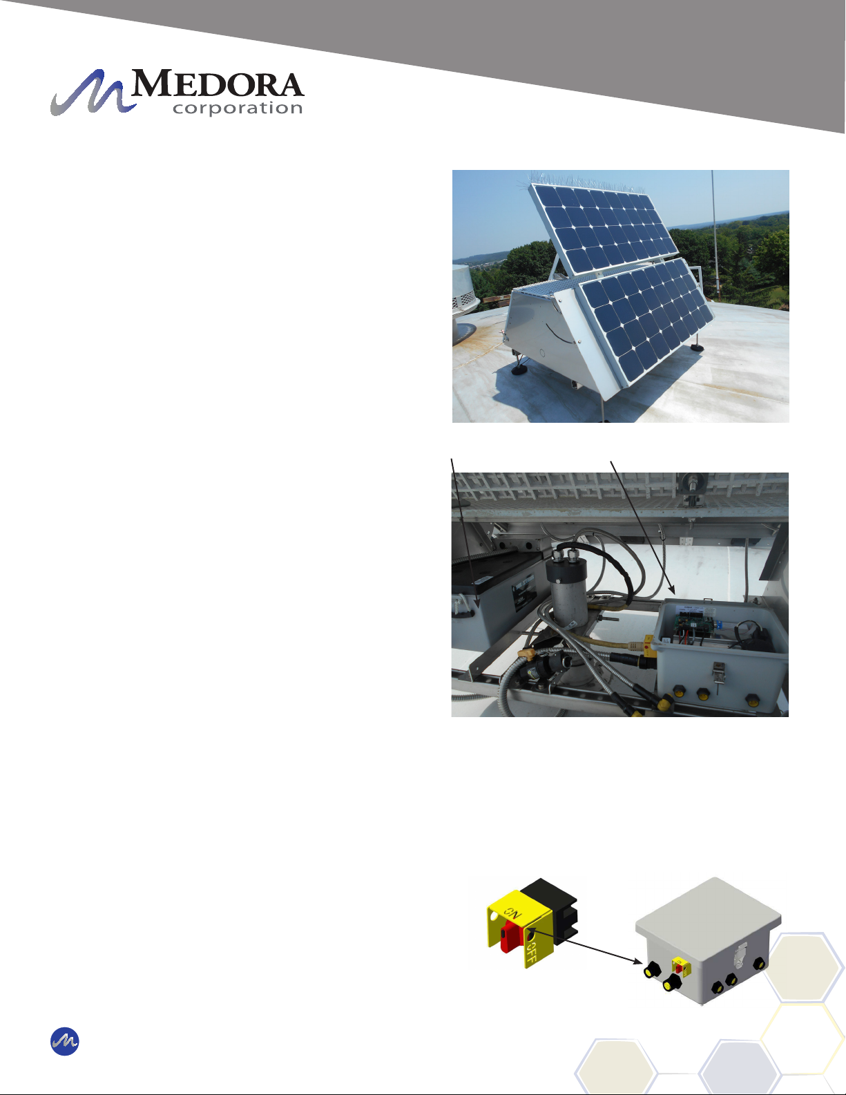
Solar / Electronics
Photovoltaic (PV) Modules -The PV modules
are often referred to as the solar panels. The
SolarBee uses 100% solar energy to provide
day/night operation. The PV modules collect
solar power to operate the machine with excess
left over to charge an onboard 12-volt, deep
cycle battery. The SolarBee has an 80-watt PV
modules which individually connect to the digital
controller. A bird deterrent is located directly
above the PV modules to prevent bird fouling.
The PV module is generally placed on a low
prole structure which encloses the controller and
battery. The PV module is positioned so it faces
the direction of best sunlight.
The low prole solar panel stand offers additional
protection by providing shading while also
allowing ventilation. Keeping the temperature
down inside the digital controller and the battery at
a lower temperature which extends the life of the
battery and electronics.
Deep Cycle Battery - The deep cycle battery
stores excess power from the PV module during
the day and operates the machine using the
stored power during the night and extremely
overcast days.
© 2019 Medora Corporation | www.medoraco.com | 866 - 437 - 8076 | [email protected]
Features
Features
SB1250PWc
10240_20191010 O&M_SB1250PWc_10239_20191105 - 5
Digital Controller - The digital controller is located
inside the the low prole solar panel stand. The
digital controller operates and monitors the SolarBee.
The digital controller is programmed with application
specic run schedule, fallback rpm, and battery charge
settings. The SolarBee's Design and Application
Engineering groups are constantly reviewing the
program to optimize operation. The digital controller
can be updated with a new program (rmware) using
a SD (Secure Digital) Card, similar to that of a digital
camera's memory stick.
All solar energy collection and motor operation are
managed by the digital controller. This component
has two primary functions: (1) To direct and divide the
power being collected by the PV module(s) between
the brushless motor and battery. (2) To serve as the
main control center that operates the brushless motor.
There are 3 PV module connections located on the
front face of the digital controller. If the onshore power
accessory was purchase, a connection will be located
on the right side face. The onshore connection is
used only in applications where onshore grid power is
desired.
The left side face of the digital controller contains the
brushless motor connection, battery connection, and
On/Off switch. The On/Off switch activates power
to the motor. When the switch is turned to the Off
position, the motor will not operate. The charging
function of the controller will continue to charge the
battery even when the switch is turned off.
SCADA outputs offering machine operation parameters
reside within the digital controller. Please contact
SolarBee if you are interested in receiving these
parameters.
Front Face Of Digital Controller
Left Side Face Of Digital Controller
© 2019 Medora Corporation | www.medoraco.com | 866 - 437 - 8076 | [email protected]
Features
Features
SB1250PWc
10240_20191010 O&M_SB1250PWc_10239_20191105 - 6

Motor Controller - The motor controller is located
near the motor just below the top plate of the
SolarBee. The motor controller is sealed in line
with the electrical cord that runs to the brushless
motor.
The motor controller on the SolarBee receives
power and signals from the main control center
located inside the external enlosure. These
signals are used to operate the brushless motor
at the commanded speed. The motor controller
also sends feedback signals back up to the main
control center.
Due to the high frequency of communication
between the motor controller and brushless motor,
the two components need to be located close
to one another. This is the primary reason for
having the motor controller located directly on the
SolarBee.
All electronic connections on the SolarBee
equipment should only be used for the inputs or
outputs that they are labeled and designed for. If
any of the leads going into the electronic controller
are disconnected, be sure when re-connecting to
place them in the proper position.
Wiring - All electric wiring includes corrosion-
resistant, industrial cords with molded, weather
and watertight connectors. The connectors
are indexed to prevent improper wiring. A
general electrical schematic can be found in the
Maintenance and Field Adjustment section.
Motor Control Cord
Durable Wiring And Connectors
© 2019 Medora Corporation | www.medoraco.com | 866 - 437 - 8076 | [email protected]
Features
Features
SB1250PWc
10240_20191010 O&M_SB1250PWc_10239_20191105 - 7
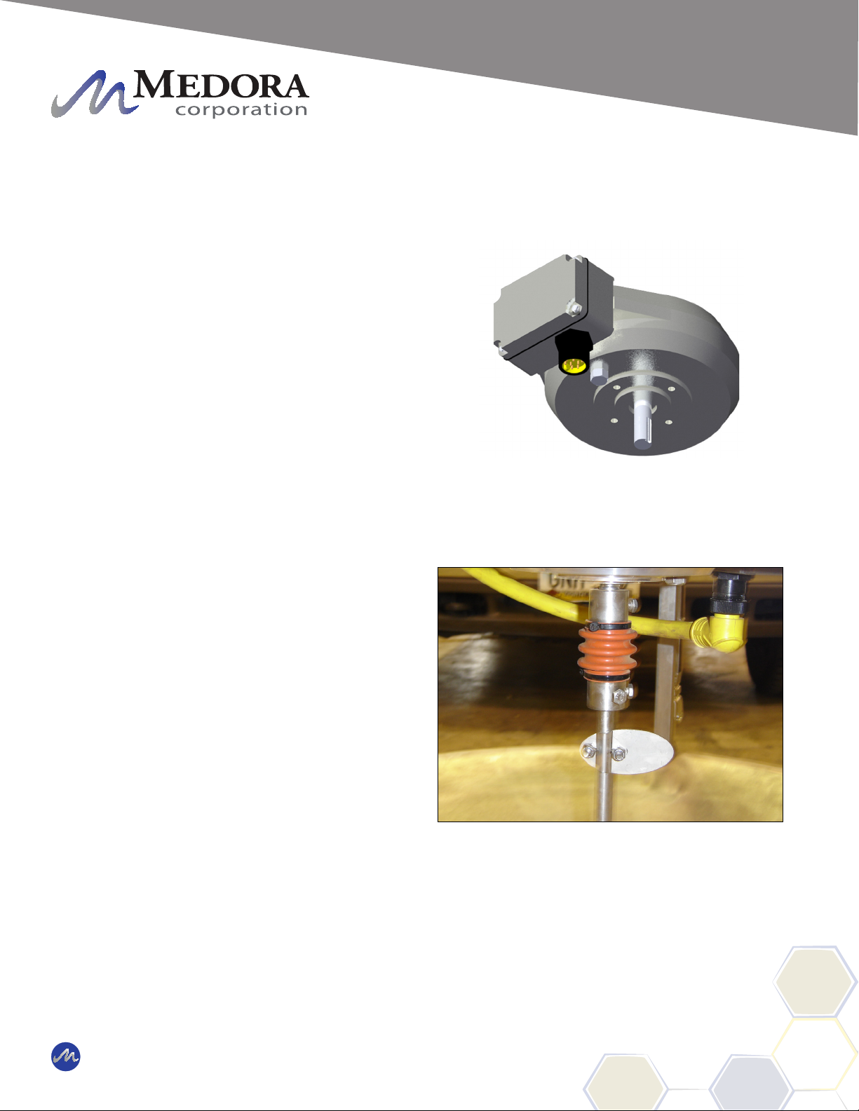
Brushless Motor / Impeller
Brushless Motor - The brushless motor is located
directly below the Top Deck. 4 bolts run down
through the Top Deck and into the housing of the
brushless motor fastening it onto the machine.
The brushless motor is built to be very durable.
The housing is constructed of casted aluminum.
The brushless motor runs very quietly and
smoothly. It does not require any maintenance. A
drive shaft extends through the bottom center of
the housing.
Shaft Coupling - The shaft coupling connects the
brushless motor drive shaft to the impeller shaft.
The shaft coupling is located directly below the
brushless motor.
The rotating assembly (motor, shaft coupling,
impeller shaft, impeller) can be removed from the
machine without disconnecting the shaft coupling.
Brushless Motor
Brushless Motor With Shaft Coupling Attached
© 2019 Medora Corporation | www.medoraco.com | 866 - 437 - 8076 | [email protected]
Features
Features
SB1250PWc
10240_20191010 O&M_SB1250PWc_10239_20191105 - 8

Impeller Assembly - The rotating assembly is
made up of the stainless steel impeller shaft,
stainless steel ag indicator, and stainless steel
impeller blades. The impeller assembly can be
removed by pulling 3 hair pins on the top plate.
CAUTION: KEEP BODY APPENDAGES
OR LOOSE CLOTHING AWAY FROM
THE IMPELLER ASSEMBLY WHILE THE
MACHINE IS OPERATING! IF MAINTENANCE
IS REQUIRED, BE SURE TO TURN THE
SOLARBEE OFF FIRST!
The ag indicator is xed to the shaft and used as
a visual indicator of the impeller shaft's rotational
speed.
A food grade oil-lled, Teon freeze sleeve
secured with o-rings surronds the impeller shaft.
The freeze sleeve is free to rotate on the shaft. If
the water should freeze around the machine, the
freeze sleeve will stand still, frozen in by the ice,
but inside the plastic sleeve, the impeller shaft will
be turning.
The impeller blades are welded to a hub that is
fastened to the impeller shaft. The impeller is
designed to gently pump water from below and
can handle up to 3-inch (7.6cm) spherical solids.
The impeller bushing is a smooth collar that the
impeller shaft tip ts into. The impeller bushing
aligns and centers the impeller shaft within the
machine.
Turn SolarBee Off Before Performing Maintenance
Flag Indicator
Impeller Blades
Impeller Hub
3 Hairpins
Rotating Assembly
Top Plate
Impeller
Shaft Tip
© 2019 Medora Corporation | www.medoraco.com | 866 - 437 - 8076 | [email protected]
Features
Features
SB1250PWc
10240_20191010 O&M_SB1250PWc_10239_20191105 - 9
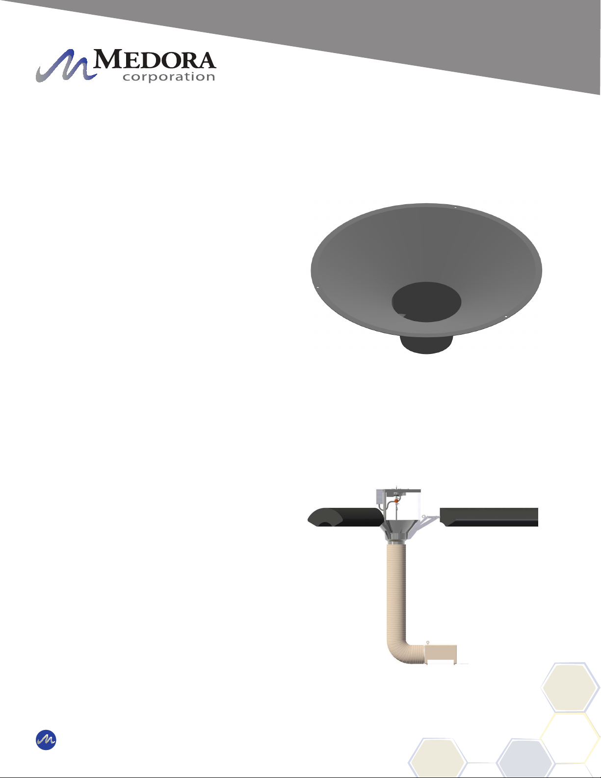
Distributor Dish / Hose
The distributor dish, structural members, structural
fasteners, and mounting brackets are constructed
of stainless steel.
Distributor Dish - Near-laminar ow is achieved
by the SolarBee due to its uniquely designed
distributor dish. The impeller rotates while sitting
within the lower half of the distributor dish. The
gentle water movement strengthens the induced
ow effect (water movement occuring between the
lower water layer entering the machine and the
upper water layer leaving the dish).
The top lip of the distributor dish is set
approximately 1-1/2 inch to 2-inch (3.8cm - 5.0
cm) below the surface of the water to achieve best
ow results. The distributor dish depth is set at
the factory and should not need adjustment after
deployment.
Hose - The hose extends from below the dish
down to the oor of the reservoir. The intake
level is generally set just above the oor of the
reservoir. As the water level uctuates, the hose
remains at a xed placement on the reservoir
oor by the use of a torque bar as the extra hose
lays on the bottom. The intake draws water
horizontally into the hose.
The contact between the torque bar and the oor
prevents the machine from rotating or moving out
of place. The machine naturally has a very small
torque due to impeller rotation.
Hose With Bend Keeping Intake Stationary
Distributor Dish
© 2019 Medora Corporation | www.medoraco.com | 866 - 437 - 8076 | [email protected]
Features
Features
SB1250PWc
10240_20191010 O&M_SB1250PWc_10239_20191105 - 10
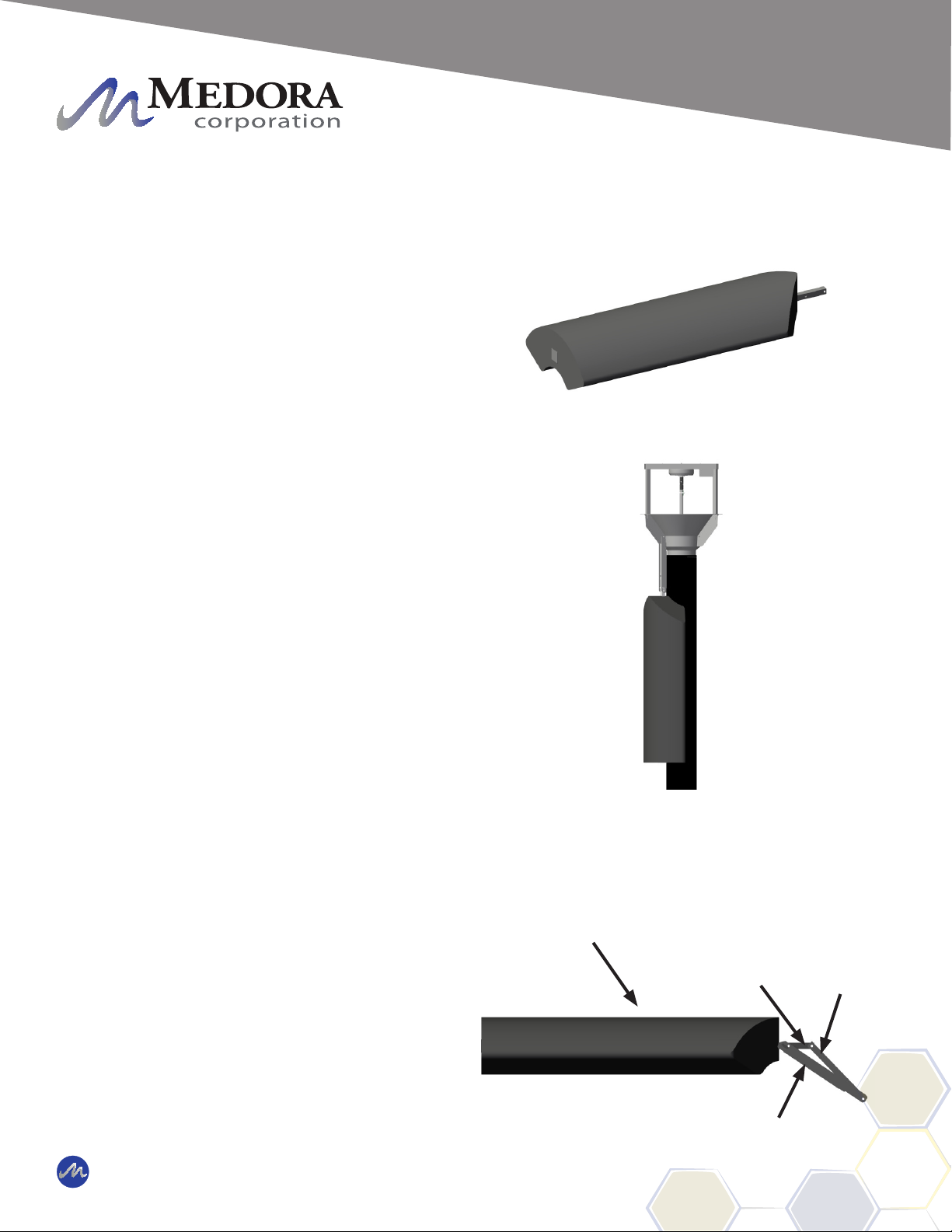
Release Channel / Floats
The SolarBee contains 3 release channels and
3 oats. The release channels allow vertical
positioning of the machine and the oats provide
buoyancy.
Floats - The oat is made from high density
Polyethylene. The oats are lled with a
Polystyrene closed-cell foam for long term
buoyancy. The stainless steel oat tube is molded
into the oat. The oat tube connects the oat
to the release channel and release tube. The
oat is shaped to hug the hose for installation
purposes allowing the machine to be installed in
a 24" square hatch. The oats have a uniquely
designed shape to:
• Minimize space when collapsed around
the hose.
• Minimize the interference with the water
ow on the surface coming off the
distributor dish.
Release Tube - The release tubes are constructed
of stainless steel. They directly connect the oats
to the central machine structure.
Float
Release
Tube
Release Channel
Collapsed Float
Float
Float Tube
© 2019 Medora Corporation | www.medoraco.com | 866 - 437 - 8076 | [email protected]
Features
Features
SB1250PWc
10240_20191010 O&M_SB1250PWc_10239_20191105 - 11

Float Assembly - The oat assembly connects
to the core unit in one location. There is no
adjustment necessary for setting the dish depth.
The oat assembly is bolted to the core unit of
the SolarBee to allow the distributor dish lip to
be automatically set to the correct depth below
the surface of the water. The depth may vary
depending on hose length being supported by the
machine and the amount of hose resting on the
bottom of the reservoir due to uctuations of the
water.
Each oat tube is connected to the central
machine structure with 1 bolt. Each oat is
connected to the oat tube by one pin. Each
oat assembly is constructed of the molded oat
and oat tube. The end of the oat tube contacts
the core unit frame when the oat is extended
into place by means of boyancy pressure when
deployed into the water.
If the machine is resting in the bottom of an empty
tank, the SolarBee will be supported against the
oats resting on the oor of the tank. Once water
is brought back into the tank, the machine will self
deploy and begin to oat.
Float Connection Points
Bolt
3/4 in to 1 in
(2.0 cm - 2.5 cm)
Distance Between Distributor Dish And Water
Level
CAUTION: DO NOT REMOVE ANY FLOAT
ASSEMBLY PINS OR BOLTS WHILE THE
SOLARBEE IS FLOATING IN THE WATER!
THE SOLARBEE MUST BE RESTING ON
THE GROUND OR SAFELY SUPPORTED
TO RELIEVE THE FORCES ON THE FLOAT
ASSEMBLY STRUCTURES PRIOR TO
DISASSEMBLY! FAILURE TO FOLLOW
THIS WARNING COULD LEAD TO SINKING
THE SOLARBEE, SERIOUS INJURY!
Eye Loop
© 2019 Medora Corporation | www.medoraco.com | 866 - 437 - 8076 | [email protected]
Features
Features
SB1250PWc
10240_20191010 O&M_SB1250PWc_10239_20191105 - 12

The performance of the Machine has proven
to increase tremendously when its operator
understands the operation of the machine
and knows how to carry out eld adjustment
procedures.
In most cases, the operator have can perform
routine checkups and eld adjustment procedures
on the Machine, by pulling the Machine to the
hatch. A large, expensive boat isn't necessary.
When tank entry is required, an inatable raft/boat
(approximately 6 ft) is deployed inside the tank.
It is extremely important that safety comes rst
every time the Machine is inspected or having
maintenance procedures performed. It is strongly
encouraged that anyone working on or near the
machine follow these rules:
Wear a personal oatation device
Stay focused and alert
Turn the Machine off before working on it
Stay clear of parts while they are moving
To turn the Machine motor off, turn the On / Off
switch to the off position. To completely power
down the digital controller, remove all power
sources in the proper sequence.
ON / OFF
SWITCH
DIGITAL
CONTROLLER
© 2019 Medora Corporation | www.medoraco.com | 866 - 437 - 8076 | [email protected]
Maintenance
Maintenance and Field Adjustment
SB / GF PW Series Mixers
10237_20191009 O&M_SB1250PWc_10239_20191105 - 13

Impeller Assembly Removal
In the case that there is buildup below the impeller that
cannot be reached, the impeller assembly can easily
be removed.
TOOLS RECOMMENDED:
Elbow High Rubber Gloves
Garbage Bag
STEP 1: With machine off locate the 3 fasteners on the
top plate that attach it to the frame and remove them.
STEP 2: Firmly grasp the top plate and pull straight up
on the impeller assembly.
STEP 3: Observe and clean any debris located on the
bottom of the impeller.
STEP 4: Observe and clean any debris located down
in the dish where the impeller rests. Place the debris
into a garbage bag and remove from pond to prevent it
from going through machine again. Follow all local
laws and regulations when disposing of any
materials collected.
STEP 5: Once clean, place impeller assembly back
in place. Be sure bottom of impeller shaft ts into the
bushing in the dish and that the 3 top plate holes are
aligned with the top of the frame.
STEP 6: Replace the 3 fasteners that were removed
in Step 1.
STEP 7: Turn machine back on.
1250PWc Impeller Assembly
500PWc Impeller Assembly
Turn Machine Off Before
Performing Maintenance
CAUTION: TURN MACHINE OFF BEFORE WORKING NEAR IMPELLER! WEAR PROTECTIVE
GLOVES AND BE CAUTIOUS OF SHARP LEADING EDGES ON IMPELLER BLADES WHILE
CLEANING! FAILURE TO FOLLOW THESE WARNINGS COULD LEAD TO INJURY!
Top Plate
Top Plate
© 2019 Medora Corporation | www.medoraco.com | 866 - 437 - 8076 | [email protected]
Maintenance
SB / GF Small Frame Impeller Assembly Removal
SB / GF Series Small Frame Mixers
2089_10245_20191001 O&M_SB1250PWc_10239_20191105 - 14
Battery Replacement
The SolarBee contains an onboard battery
located in the electronic controller that will require
infrequent replacement. Between 2 and 3
replacments are expected over the course of the
machine life.
TOOLS RECOMMENDED:
NO TOOLS REQUIRED:
STEP 1: Open the solar panel stand access panel
located opposite side of the solar panel.
STEP 2: Locate the electronic controller and
the On/Off switch. Turn the switch to the "OFF"
position.
STEP 3: Refer to proper Power Down Procedure
located in the Electrical Section.
STEP 4: With the SolarBee off, unscrew the
battery lead from the battery terminal.
STEP 5: Slide the battery out of the panel stand
box.
IMPORTANT NOTE:
The battery weighs approximately 140 lbs
and may require two people to handle.
STEP 5: Install new battery into position and
connect battery lead back up to the battery
terminal.
STEP 6: Refer to the proper Power Up Procedure
located in the Electrical Section.
STEP 7: Turn the On/Off switch back to the "ON"
position.
STEP 8: Be sure the SolarBee is operating
correctly and close the access panel.
Battery Disposal: Be sure to follow local
law and regulations when disposing of the
used up battery!
Solar Panel Stand Open With
Controller And Battery
Battery
Electronic
Controller
DIGITAL
CONTROLLER
ON / OFF
SWITCH
* * Failure to follow these steps could
result in component damage. * *
© 2019 Medora Corporation | www.medoraco.com | 866 - 437 - 8076 | [email protected]
Maintenance
Battery Replacement
SB Series Potable Water
2086_10274_20191001 O&M_SB1250PWc_10239_20191105 - 15

Tank Maintenance
The machine is designed to rest on the oor of the tank in an event when the tank is drained. If the machine is
left undisturbed, the machine will naturally oat and self adjust when the tank is relled.
During the event that a potable water tank is taken off-line for maintenance for re-coating, sandblasting, or
cleaning, a few considerations need to be followed for the care of the machine. The best solution for the care
of the machine is to remove the unit from the tank until the maintenance is complete. Often times there is an
access hatch thru the side of a tank which the machine in most cases can easily be removed. Sometimes this
is not an option and the following guidelines should be followed in the event of interior tank work.
STEP 1: Turn the machine circulation equipment "Off"
if the tank is projected to be dry for more than a few
days. The On/Off switch is located in the machine
electronic controller mounted to the pv module stand.
STEP 2: Cover the entire machine, including the hose
and intake assembly, using a heavy duty tarp. Be
sure to tuck the tarp under the machine to avoid any
sand being collected on the machine in the case of
sandblasting.
STEP 3: The electrical cord and chemical injection cord
will be suspended from the ceiling so extreme care
needs to be taken to prevent damage to the cord and
hose from any abrasions from blasting. Both injection
and electrical may be disconnected and coiled up
under the tarp if desired.
STEP 4: Once the maintenance is complete, remove
the tarp and reconnect the electrical cord and chemical
injection hose (if applicable). The machine may need
to be cleaned from any dust or sand that may have
made it’s way thru the tarp. A key component that
should be checked and cleaned is the impeller bushing
and impeller tip. Please follow the proper procedure
earlier in this section.
Machine power cord laying tangle free.
Machine resting on oor ready for water.
© 2019 Medora Corporation | www.medoraco.com | 866 - 437 - 8076 | [email protected]
Maintenance
Tank Maintenance
SB / GF Series Mixers, Potable Water
2088_10252_20191022 O&M_SB1250PWc_10239_20191105 - 16

Tank Maintenance continued,
STEP 5: Decontaminate the machine by wiping all
machine surfaces using a bleach/water solution and a
towel or cloth. Remove all excess dust, sand, etc. Do
not use a pressure washer to clean the machine.
This may damage the on-board electronics which may
result in improper operation of the machine.
STEP 6: The machine intake needs to be placed in its
original position and the entire hose layed out across
the oor. The hose should not be coiled or draped
over the machine! Reposition the electrical cord
and injection hose so they do not get tangled on any
objects.
STEP 7: The machine is now ready for the tank to be
lled with water and be turned “On”.
Most customers feel that removing the machine
circulation equipment is the best option for the safety of
the equipment. Removing the equipment also allows
for the contractors to perform their work freely and not
have to maneuver around the machine.
Please contact Medora Corporation Customer
Service, 1-866-437-8076 (customerservice@
solarbee.com), for a quote for temporary removal
of your machine.
Hose properly layed out on tank oor.
Machine resting in drained tank.
© 2019 Medora Corporation | www.medoraco.com | 866 - 437 - 8076 | [email protected]
Maintenance
Tank Maintenance
SB / GF Series Mixers, Potable Water
2088_10252_20191022 O&M_SB1250PWc_10239_20191105 - 17

Low Prole Stand
Digital Controller
(Inside Low Prole)
Battery
(Inside Low Prole)
PV Module(s)
Solar Panel(s)
(1 - 3 Depending on Machine Model)
PV Inputs
(1 - 3)
Outside of Reservoir (Inside Low Prole)
Inside of Reservoir
Motor Power and
SCADA Signals
Motor
Motor
Controller
Optional:
120 VAC 60 HZ @ 2.0 AMPS
240 VAC 50 HZ @ 1.0 AMPS
GRID POWER BACKUP (OPTIONAL)
CONNECTED ON OPPOSITE
FACE OF CONTROLLER
© 2019 Medora Corporation | www.medoraco.com | 866 - 437 - 8076 | [email protected]
Electrical
General Electric Overview for Potable Water SolarBee
(Low Profile)
1148_10154_20191002 O&M_SB1250PWc_10239_20191105 - 18
Table of contents
Popular Tank Equipment manuals by other brands

Regulus
Regulus RBC 200 Installation and operation manual

Endress+Hauser
Endress+Hauser silometer FMC 671 Z Operating instruction

Graf
Graf SAPHIR Installation and maintenance instructions

RED
RED LOGIKA REFILL installation guide

Amtrol
Amtrol FIRE-X-TROL FPT-5 Installation, operation & service instructions

Sealey
Sealey TP95 instructions


