Sealey TP95 User manual

Petrol is a highly flammable liquid and any spillage will evaporate to form a flammable, heavier than air vapour which is easily ignited.
Common ignition sources include, but are not limited to, smoking and light matches, welding and cutting equipment, heaters, all types of
electrical equipment unless specifically designed as suitable for use in flammable atmosphere. Even low voltage inspection lamps, if
damaged can ignite petrol vapour
Please take time to read the following safety information before commencing work with the TP95.
! Use the tool only for its intended purpose.
! Familiarise yourself with this product’s applications and limitations, as well as the specific potential hazards peculiar to this tool.
! Use original Sealey spare parts only. Non-recommended parts may be dangerous and will invalidate the warranty.
!We recommend that the TP95 is used outdoors or in a well ventilated area, and well away from pits or other openings in the ground
where vapour can collect.
!Disconnect the vehicle's battery before draining fuel.
!Keep a foam or dry powder fire extinguisher nearby.
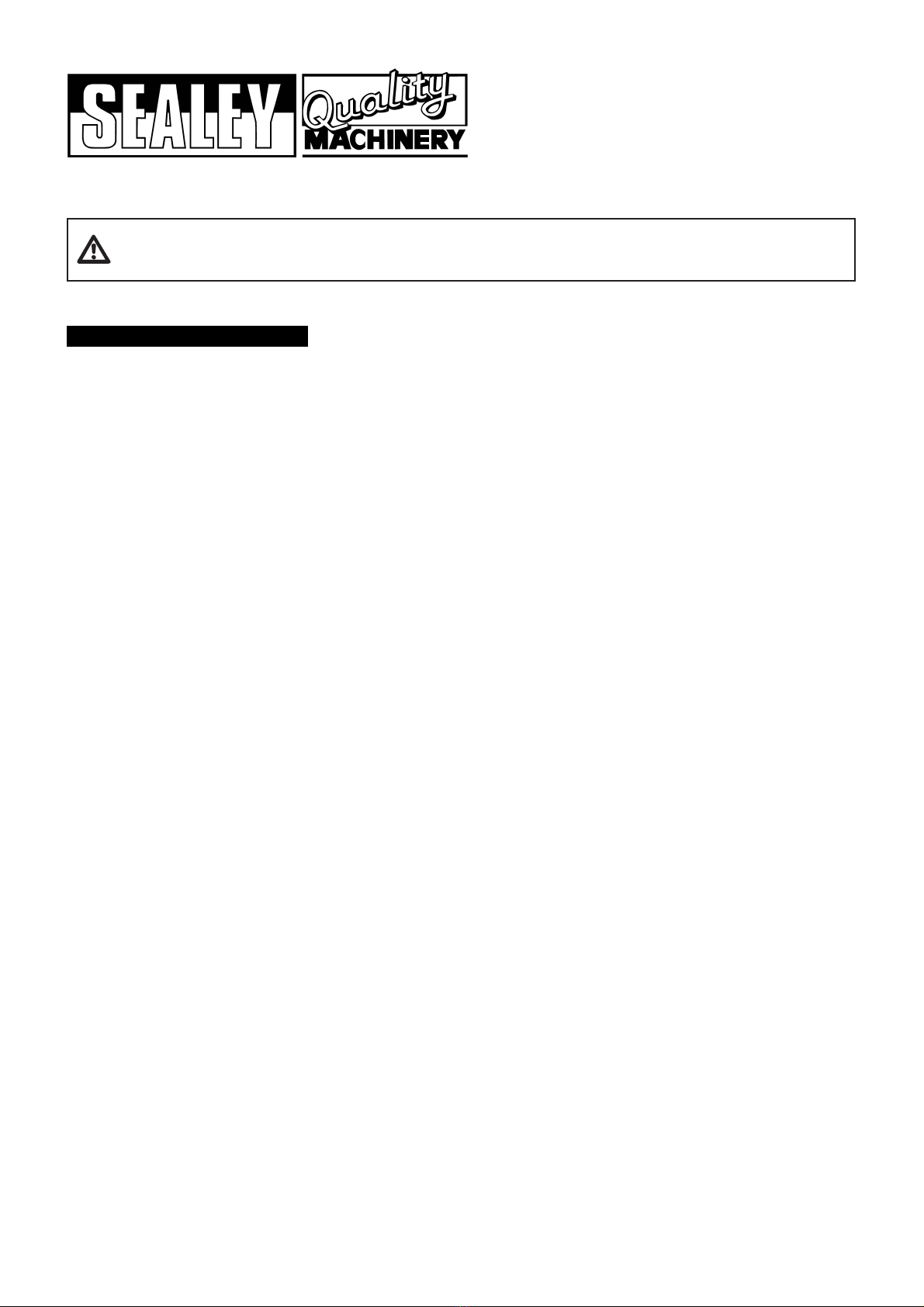
!Ensure containers cannot easily be knocked over during filling.
!Ensure containers are large enough to hold the contents of the fuel tank you are draining.
! Ensure space required for use and maintenance of the tool is adequate, free from unrelated materials and has good lighting.
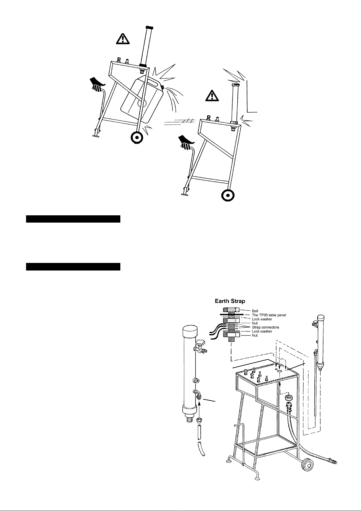
! Attach earth lead to the fuel container using the and crocodile clip supplied.
!Always use the earth bonding strap by connecting one end to the vehicle chassis away from any potential fuel vapour and the
other end to a suitable earthing point.
!Remove all combustible materials from the work area.
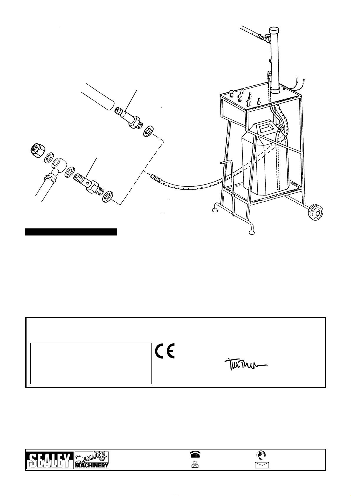
! Use only a container (not included) rated for the fuels used. Ensure that the container mouth is as narrow as possible and still
allow insertion of the drain hose.
!HSE guidance recommends use of metal containers with secure caps for holding drained fuel.
!Mark fuel containers with hazard labels to show their contents.
!Keep any fuel containers in a well ventilated, lockable store, preferably outside the working area.
!Soak up any spill immediately using absorbent granules or similar material.
! Keep children and unauthorised persons away from the working area, especially when the tool is in operation. Keep the work
area childproof by using padlocks and master switches.
! Maintain the tool in top condition. Keep it clean for best and safest performance.
!Follow the same precautions when transferring fuel from the retriever back into the vehicle or into any other container.
#Do not use this tool for anything other than its intended purpose. The TP95 is only to be used for pumping fuel from diesel or petrol
fed vehicles.
#Do not work on a fuel tank or remove a sender unit before draining the fuel.
#Do not use an open flame or smoke anywhere near the tool or around stored fuel.
#Do not drain fuel into open-topped containers such as buckets and watering cans.
#Do not drain fuel into dedicated workshop oil drain equipment.
#Do not drain fuel into plastic containers except for quantities less than 10 litres.
#Do not allow work which can produce a source of ignition, such as welding, electrical or other hot work, to be carried out
while draining petrol.
#Do not drain fuel over or close to a pit or drain because of the risk of flammable vapour accumulation.
#Do not use any electrical equipment on or near the vehicle while fuel draining is in progress. This includes the use of
inspection lights, cordless/mobile phones or pagers.
#Do not store drained or contaminated fuel in the workplace unless it is to be returned to the vehicle immediately.
#Do not add drained fuel to the waste oil tank.
#Do not wear clothing on which petrol has been spilt - stop work and change into uncontaminated clothing before continuing to work.
# Do not handle the unit with the collection tank on the lower table. The unit can become unstable and overturn.
# Do not use the drainer if the pump is damaged in any way.
# Do not stand on the frame.
# Do not leave pump running when unattended. Turn it OFF and do not leave area until it has come to a complete stop.
# Do not use whilst under the influence of drugs, alcohol or other intoxicating medication, or it you are fatigued.
# Do not force the tool to do a job it was not designed to do.
1. SAFETY INSTRUCTIONS
INSTRUCTIONS FOR:
PNEUMATIC FUEL TANK DRAINER
Model No: TP95
(The use of symbols in this document is to attract your attention to possible danger. The symbols and warnings themselves do not eliminate any danger, nor are they
substitutes for proper accident prevention measures).
Thank you for purchasing a Sealey product. Manufactured to a high standard this product will, if used according to these instructions
and properly maintained, give you years of trouble free performance.
IMPORTANT
BEFORE USING THIS PRODUCT, PLEASE READ THE INSTRUCTIONS CAREFULLY. MAKE CAREFUL NOTE OF SAFETY INSTRUCTIONS,
WARNINGS AND CAUTIONS. THIS PRODUCT SHOULD ONLY BE USED FOR ITS INTENDED PURPOSE. FAILURE TO DO SO MAY CAUSE
DAMAGE OR PERSONAL INJURY, AND WILL INVALIDATE THE WARRANTY. RETAIN THESE INSTRUCTIONS FOR FUTURE USE.
TP95 - 2 - 200307
Users/Businesses should perform their own hazard risk assessment based on their
specific environment and following the guidelines laid out above.

To use the TP95, you will need a compressed air supply (lubricated, filtered and dehumidified with a minimum pressure of 5 bar, 1/4” union
and minimum hose diameter of 8mm) and a container suitable for storing fuel (see illustrations).
3.1. Remove parts from the packing and check that all the following items are included:
3.1.1. Frame assembly with union kits (tightened on the upper
table) and handle.
3.1.2. Fuel suction hose fitted with clamps and unions.
3.1.3. Drain hose.
3.1.4. Spacer (for fastening the pump)
3.1.5. Pump assembly.
3.2. The handgrip on table assembly has been packed with
handle facing inward. Once out of the packing, It needs to
be assembled so the handle faces outward.
3.2.1. Remove the screw and nut at the handle base.
3.2.2. Turn the handle so it faces outward.
3.2.3. Replace screw and nut to secure the handle in position.
3.3. Assembling the pump.
3.3.1. Attach drain hose to the pump inlet (A) with a spanner.
3.3.2. Pass the drain hose through the upper table hole and
place the pump into its housing (B).
3.3.3. Secure the pump from below with the spacer.
3.3.4. Attach the suction hose to the bottom of the pump.
3.4. Earth strap connection
3.4.1. Pass bolt through designated TP95 table hole (X).
3.4.2. Fit locking washer, nut, three strap connectors, 2nd lock
washer and 2nd nut (fig 1).
3.5. Attach the pump to the air supply (C).
3.5.1 Place a suitable fuel container on the bottom table (D).
3.5.2. Insert the drain hose into the fuel container. The hose should
be as deep into the can as possible without touching the
bottom so as to reduce possibility of splashing. Be sure the
hose does not touch bottom.
3. ASSEMBLY AND SETUP
A
BX
Height ..........................................................1400mm
Width ............................................................500mm
Length ..........................................................720mm
Weight ..........................................................17kg
2. SPECIFICATIONS
Air Consumption ..........................................10 l/min
Capacity........................................................15 - 20 l/min
Maximum Working Pressure ........................3 - 4 bar
TP95 - 2 - 200307
# Do not handle the unit with the collection tank on the lower table. The unit can become unstable and overturn.

4. OPERATION
CD
TP95 - 2 - 200307
The TP95 is only to be used for pumping fuel from diesel or petrol fed vehicles. Any other use can be dangerous and will invalidate
the warranty. Bring the unit near the vehicle when ready to begin transferring fuel. Pumping can be carried out in different ways depending
on the vehicle’s configuration.
Before beginning the draining process, ensure you have read and understood the safety warnings and guidelines listed in Section 1
of these instructions.
4.1.Carburettor engine vehicles. Fuel can be transferred from carburettor engine vehicles through the carburettor’s fuel inlet pipe.
If this is necessary, use one of the three ‘fishbone’ connectors supplied. Each has a different diameter.
4.1.1. Attach the correct size connector and washer to the suction hose (‘E’ on illustration next page).
4.1.2. Disconnect the fuel inlet hose and attach it to the suction hose connector.
4.2. Fuel injected vehicles. Fuel can be transferred from fuel-injected vehicles through the injector’s fuel inlet pipe.
4.2.1. Choose a connecter with the required diameter and attach it to the suction hose (‘F’ on illustration next page).
4.2.2. Disconnect the vehicle’s fuel inlet pipe coming from the tank.
4.2.3. Use the two gaskets from the ring removed from the car to obtain a better seal and attach the connector to the air inlet pipe.
4.3. Connect the earth bonding strap.
Ensure strap is tightly connected to unit table as described in chapter 3. First clamp one end of the strap to the vehicle grounding
point away from any potential fuel vapour, and the other end of the strap to a suitable earthing point. Ensure the fuel container is
also connected to the earth strap, if neccesary scrape away a small amount of paint from the container to improve the earth
connection.
4.4. Transferring fuel directly from the tank.
4.4.1. Access to the tank may be gained from the boot through a porthole, closed by a guard or a safety device, if the vehicle is fitted with
an antitheft device at the fuel tank inlet. Remove the guard, carburettor float and the relevant cap and insert
the suction hose into the hole without any union. This will allow quicker transfer of fuel than the previous two methods.
4.4.2. In older vehicles, the suction tube can be inserted directly into the fuel tank through the fuel tank inlet.
4.5. Start the pump suction by opening the air inlet valve. The air pressure should be set to 3-4 bar. Higher pressures provide no
benefit and may impair or damage the pump. Do not completely open the valve or run the pump at its maximum speed. When
using connections as recommended in 3.1 and 3.2, transfer time may take about 15 minutes. When transferring directly through the
suction tube, transfer time is about 3-4 minutes.
4.6. Turn the pump off by closing the air inlet after all the fuel has been transferred.
The pump will cavitate when fuel transfer is complete. Be sure to turn it off as soon as possible as prolonged cavitation may damage
the pump.
4.7 Unless the fuel is to be returned to the vehicle immediately, it should be stored in a designated lockable, well-ventilated area,
preferably outside the workshop.
4.8 Any contaminated petrol or petrol/diesel mixtures should be consigned to waste, giving a clear description of the nature of the
material.

5.1. Maintenance, service and repair should only be carried out by qualified persons.
5.2. Clean the pump silencer at least once a month to remove oil residue. Remove it from the pump housing and place it in a detergent
solution for 2 hours. Dry it with compressed air and place it back in the pump housing.
5.3. Check the condition of the transfer hoses. Make sure that they are intact and undamaged, without cracks, holes or leaks. If they are
damaged or they leak, replace them.
5.4. Check the condition of the teflon gaskets and the ‘fishbone’ connections. Be sure that they are undamaged and can maintain a
perfect seal. Replace them with original spare parts if they are damaged or not working correctly.
5.5. Periodically check the earth strap terminals for tightness and that the wire and clamps are in good order.
5. MAINTENANCE
E
F
Declaration of Conformity
We, the sole importer into the UK, declare that the product listed below is in conformity with the following standards and directives.
The construction file for these products is held by the Manufacturer
and may be inspected on request by contacting Jack Sealey Ltd
For Jack Sealey Ltd.
Sole importer into the UK of Sealey Power Products
Pneumatic Fuel Tank Drainer Model No: TP95
89/392/EEC
Machinery Directive (1992 SI No. 3073) Signed by Tim Thompson 1st March 2007
NOTE: It is our policy to continually improve products and as such we reserve the right to alter data, specifications and component parts
without prior notice.
IMPORTANT: No responsibility is accepted for incorrect use of this product.
WARRANTY: Guarantee is 12 months from purchase date. Proof of purchase will be required for any claim.
INFORMATION: Please call us for a copy of our latest catalogue
01284 757500
01284 703534 sales@sealey.co.uk
Sole UK Distributor
Sealey Group,
Bury St. Edmunds, Suffolk.
www.sealey.co.uk
Web
email
Table of contents
Other Sealey Tank Equipment manuals