Meech CyClean User manual

1
Operating Manual
CyClean™
Non-Contact Web Cleaning


3
CONTENTS
CYCLEAN SYSTEM OVERVIEW 5
Model and Function 5
Double Sided Cleaning 6
Correct Use of a CyClean System 6
How CyClean Works 6
UNPACKING THE SYSTEM 6
SUGGESTED ORDER OF INSTALLATION 7
SYSTEM INSTALLATION - MECHANICAL/ELECTRICAL 7
Positioning of the System 7
Required Space and Mounting Holes 7
Web Direction and Tension 8
Head Orientation/Opening Options 8
Standard Web Gap and Adjustment 9
Connecting the Active Ionisation Equipment 10
Connecting the Remote On/Off Signal from the Line 12
SYSTEM INSTALLATION - PNEUMATIC 13
Compressed Air Requirement 13
Compressed Air Connections 13
Setting the Required Air Pressure 14
Adjustment of Head Opening & Closing Speed/Force 14
Compressed Air Circuit 15
SYSTEM INSTALLATION – VACUUM SYSTEM 15
SYSTEM INSTALLATION – DUCTING 15
OPERATING THE SYSTEM 16
Before Use 16
System Setup 16
MAINTENANCE AND INSPECTION 17
Inspection 17
Maintenance – Ionisation Equipment 18
Fault Finding – Ionisation Equipment 18
Maintenance – Vacuum System 18
SPARE PARTS 19
TROUBLESHOOTING 20
DRAWING PACK 21
Ducting 21
CyClean Head – Manual Opening 24
CyClean Head – Pneumatic Opening 29
Pneumatic Control Box Wiring Diagram 41
Declaration of Conformity 42


5
CyClean™ System Overview
Models and Function
The Meech CyClean has been designed in response to increased demand for a compact, high performance, non-contact web
cleaning system.
Through the application of advanced computational uid dynamics, Meech has optimised the cleaning efciency of CyClean to
remove and extract contamination as small as 0.5 micron.
The Meech CyClean provides the following user advantages:
Excellent contamination removal – removing particles as small as 0.5 micron.
Non-contact cleaning – suitable for a wide range of substrates.
Compact design - easier to install in cramped areas.
Continuous cleaning – no need to stop the web.
Static control – we will be contamination and static free on exit.
Double Sided Cleaning
CyClean is available as a double sided web cleaning system; single sided variants are not available.

6
Correct Use of a CyClean System
Meech CyClean web cleaning systems should only be used in installations for which they are designed.
If the CyClean is used in any other way than instructed in this manual, it will be considered as improper use.
How CyClean Works
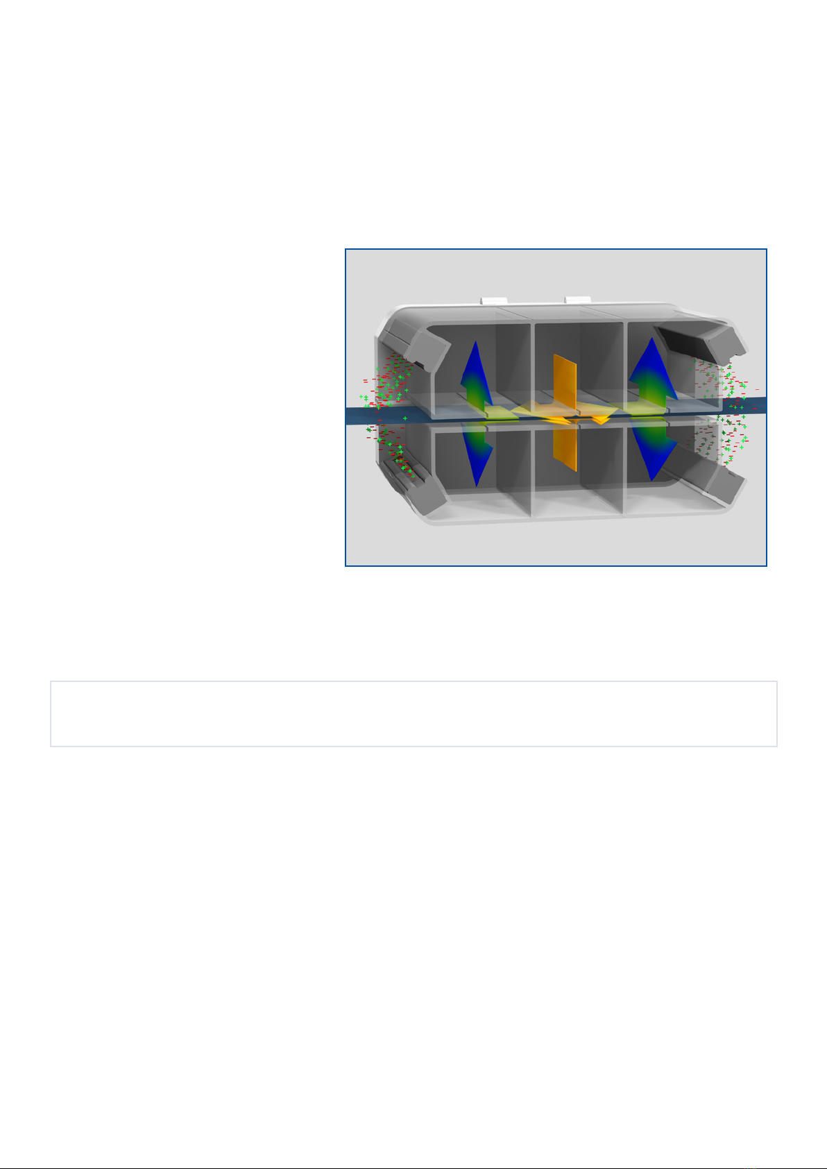
The excellent cleaning performance of CyClean is achieved from the combination of the following processes.
The web passes through a cloud of ionisation on entry to the CyClean head, which neutralises any static charges.
The web is then subject to a force of turbulent
air created by the blowing and vacuum airows
within the head unit.
High frequency micro-movements of the web
are created by the turbulent air.
The combination of the high frequency
micro-movements and turbulent air shatters
the web boundary air layer, releasing the
contamination into the vacuum airows.
As the web exits the CyClean head, it passes
through a second cloud of ionisation to prevent
re-contamination of the web.
Unpacking the System
CAUTION
Observe correct manual handling procedures when removing the system from the packaging. It is likely that the system will
exceed the recommended manual handling limit.
The CyClean will be delivered in a heavy duty wooden packing crate.
On receipt of the system, check the packaging for signs of shipping damage. If found, any damage should immediately be
reported to the shipping company, the supplier of the system and Meech directly.
Inside the packing crate check the system for signs of damage. If found, any damage should immediately be reported to the
supplier of the system and Meech directly.
Before installation of the system, it is recommended that you clean it to remove any potential packing contamination.

7
Suggested Order of Installation
For ease of installation, it is recommended that the system components be installed in the following order:
1. Position and mount the head unit (the web must enter the head unit so that it reaches the aerodynamic ap before the
blowing air slot).
2. Position and mount the Air Handling Unit (in free air to avoid overheating and considering the available ducting lengths).
3. Position and mount the control box (note the distance to the head and AHU and check the required cable lengths are
available).
4. Make all the electrical connections.
5. Make all compressed air connections (if required).
6. Connect all ducting.
System Installation - Mechanical/Electrical
IMPORTANT
When installing the CyClean system, it should be positioned so that the web passes straight through the system.
IMPORTANT
Installation of the CyClean system should only be completed by those with suitable qualications.
Positioning of the System
The CyClean system should be installed in the position that was recommended by your Meech contact. The exact installation
location will vary depending on the machine and application requirements.
In general, the CyClean system should be installed as close to the critical process as possible to minimise the potential of
re-contaminating the web via airborne contamination.
Required Space and Mounting Holes
Please view the drawing section at the end of this manual for GA drawings and mounting hole positions.

8
Web Direction and Tension
The CyClean must be mounted with the web passing through the unit so that it reaches the aerodynamic ap before the blowing
air slot.
1
1
2
2
3
3
4
4
A A
B B
C C
D D
Web
Direction
Web
Direction
IMPORTANT
The web must be kept under tension whilst the unit is running.
Head Orientation/Opening Options
The CyClean head can be installed in any orientation without jeopardising cleaning performance. The CyClean head will be
supplied to open/close with one of the two following options.
Manual
This opening method is standard for systems suitable for a maximum web width of up to 600mm.
This option should only be used for heads that are installed on a horizontal web. The top half of the head opens upwards by
manual operation.
1
1
2
2
3
3
4
4
A A
B B
C C
D D
Manual
Opening
Pneumatic
This opening method is standard for systems suitable for a web width range of 601mm to 2,000mm. Systems for narrower web
widths can be upgraded to pneumatic opening. This option can be installed so that the head unit opens at any angle. The moving
half of the head unit can be controlled locally or remotely to allow full line integration.
1
1
2
2
3
3
4
4
A A
B B
C C
D D
Fixed Half

9
Standard Web Gap and Adjustment
The web gap is the total distance between the two halves of the CyClean head that the web passes through.
Manual Opening
The web gap is xed at 8mm and is not adjustable.
Pneumatic Opening
The web gap is 8mm as standard. It can easily be adjusted by changing the cones and cups located in each corner of the head
unit.
The cone and cup range available and the web gap created by each is shown in the following table.
Black + Black = 8mm
Black
Blue
m
m
m
+
+
Blue
Blue
= 9mm
= 10mm

10
Connecting the Active Ionisation Equipment
The CyClean system is supplied with the following active ionisation equipment:
Qty 4 x Meech Model A914 Ionising Bars that are installed in the CyClean head unit.
Qty 1 x Meech Model A905 Ionising Power Supply for systems to suit web widths up to 1,000mm, or, qty 2 for systems to suit
web widths of 1,001mm or greater.
Connecting the Active Ionisation Equipment
Before making any connections ensure the unit is disconnected from the mains.
The Meech Model A905 ionising power supply has 4 ionising appliance connection ports (2 on each side). Remove the lid of the
905 by unscrewing the three retaining screws, select the required number of ports, one per ionising bar, and remove the
necessary grommets from the ports.
Connect the ionising bars by removing the lock washer and nut from the swivel connector of the appliance.

11
Push the connector through a port in the power supply adjacent to the high voltage terminal.
Then ret both the lock washer and nut to the ionising bar. Ensure that the nut is fully tightened.
Connect the cable eyelet of the ionising bar to the high voltage stud of the 905 using the screw provided. Ensure that the nut of
the ionising bar connector is fully tightened.
2mtr mains lead and IEC plug are supplied for connection to the 905. Insert the IEC plug into the IEC socket of the 905 ensuring
the illuminated ON/OFF rocker switch is in the OFF position.
Connect the free end of the mains cable to the mains supply.

12
IMPORTANT
For safety reasons this equipment must be grounded / earthed either via the mains plug or by direct connection to ground /
earth.
Switch on the ionising system via the illuminated ON / OFF rocker switch of the 905.
In normal operation the ON / OFF switch will be illuminated red and the High Voltage indicator will be illuminated green.
Connecting the Remote On/Off Signal From the Line
The following applies if your system has pneumatic opening and closing.
Connect a normally open (NO) signal from the line in the CyClean control box as shown in the image below and consult the wiring
diagram in this manual.

13
System Installation - Pneumatic
The following applies if your system has pneumatic opening and closing.
IMPORTANT
Installation of the CyClean system should only be completed by those with suitable qualications.
Compressed Air Requirement
The CyClean system requires a compressed air supply to open and close the head unit.
The compressed air supply should meet the following specication:
3-7 bar (43-100psi)
Clean and dry compressed air
Compressed Air Connections - Control Box
The main incoming compressed air supply should be connected to the 4mm compressed air push t tting on the CyClean control
box labelled Air In 1.
The compressed air hoses (blue and black) should be connected from the CyClean unit to the 4mm compressed air push ttings
labelled Port 2 and Port 3. The blue hose connects to port 2, the black hose connects to Port 3.
Compressed Air Connections - Cylinders
The system is supplied with a pneumatic hose loom for connection of the cylinders and a 5mtr length of pneumatic hose for
connection of the loom to the control box.

14
Setting the Required Air Pressure
There is a pressure relief regulator valve inside the CyClean control box. Adjusting this valve will change the air pressure that will
be fed to the cylinders mounted as part of the CyClean head.
This valve will have been set at Meech before your system was supplied.
CAUTION
If you need to adjust the pressure relief valve, make sure that it is not adjusted to provide maximum pressure. If too high a
pressure is used, it may result in damage to your system.
Adjustment of Head Opening and Closing Speed/Force
The speed/force at which the CyClean head opens and closes can be independently adjusted. This will be adjusted by Meech
before your system is supplied so that:
Open = medium to fast operation
Close = slow speed
The speed can be adjusted using the valves on each of the cylinders.
IMPORTANT
When making any adjustment it is very important that all 4 cylinders are adjusted at the same time to the same setting. If this
does not happen it can damage your system.
CAUTION
It is recommended that the closing speed/force of the head is minimal, as this is a pinch point that could cause injury.

15
Compressed Air Circuit
Please view the drawing section at the end of this manual for a circuit diagram.
System Installation – Vacuum System
Systems for up to a web width of 1,400mm are supplied as standard with an Air Handling Unit (AHU).
Systems for a web width of 1,401mm or greater are supplied with an AHU and Secondary AHU.
Consult the AHU manual for full installation and operation instructions.
System Installation – Ducting
Meech offers 3 standard ducting kits that are detailed below. Each kit allows the CyClean head to be 5mtrs from the AHU.
There is a drawing of each kit in the drawings section at the end of this manual.
Manual Opening
Pneumatic Opening up to 600mm web width
Pneumatic Opening greater than 601mm web width
When installing ducting, it is important to make sure that the length of ducting for the blowing and vacuum airows is equal in
length and that the same diameters are used.
Ducting should be cut to length to keep duct runs as short as possible.
Any bends in the ducting should be smooth and tight bends should be avoided. Once installed, check to make sure all duct
connections are tight and that the duct is not damaged in any way.

16
Operating the System
Before Use
Before using the CyClean system it is important that you have read and fully understand this manual.
IMPORTANT
Testing of the system is recommended before it is used for full production.
System Setup
The airows of the CyClean non-contact web cleaning system should be adjusted to achieve optimum cleaning results.
The best cleaning results will be achieved, when the system is set to have a positive airow into the CyClean head, on both the
web entry and exit sides (minimising the risk of any recontamination).
The positive airow into either side of the CyClean head is adjusted by bleeding off a volume of the blowing (positive) airow to
create an airow bias in favour of vacuum.
Consult the AHU manual for full instructions of how to balance the airows.
The CyClean is now ready to use.
It is recommended that you monitor the system when it is rst tested. If any problems are highlighted, please stop using the
CyClean system and contact Meech International or your local distributor.
1
1
2
2
3
3
4
4
A A
B B
C C
D D
Positive Airflow in
Positive Airflow in
Positive Airflow in
Positive Airflow in
Web

17
Maintenance and Inspection
IMPORTANT
Always make safe the electrical and compressed air supplies before undertaking any maintenance work on the CyClean system.
IMPORTANT
Maintenance should only be completed on the CyClean system by those with suitable qualications.
Inspection
The system will perform without serious deterioration, giving many years of service, providing the following visual inspection is
made weekly.
Head Unit
Check for any external damage and the alignment of the head unit. Wipe over to remove any contamination present. Inspect that
the cables from the ionising bars to the ionising power supplies and that those from the servo drives to the head unit are secure,
free from damage and that they do not have any tight bends in them.
Vacuum System
Listen for any sounds that are not ‘normal’ i.e, grinding or scraping.
Filtration
Check that the lter warning lights on the AHU are not lit when running. Check for any external damage to the lter media, i.e.
rips. Check to make sure the lter bag is not blocked.
Ducting
Visually inspect the ductwork look for any lose sections or holes. Check to make sure the ducting is not blocked.

18
Maintenance – Ionisation Equipment
IMPORTANT
Always make safe the electrical and compressed air supplies before undertaking any maintenance work on the CyClean system.
IMPORTANT
Maintenance should only be completed on the CyClean system by those with suitable qualications.
Ionisers require periodic cleaning. During normal operation, dirt will build-up on the emitter pins and upon the body of the ioniser.
This will cause a reduction in performance.
Typically, weekly cleaning is sufcient. However, equipment used in some heavy contamination areas, such as gravure printing
or where plastic fumes are present, may require daily cleaning. Equally, in a Class 100 area, cleaning may only be required on a
monthly basis.
Advanced systems with performance monitoring, e.g 977cm and 904cm, will alert the operator to the need to clean the equipment
before performance drops to an unacceptable level.
Before cleaning, ensure that the equipment is switched off.
Emitter pins can be cleaned very effectively with a brush. A dry toothbrush is ideal.
Ionising bars will need periodic wiping to clean grey deposits from the surface of the bar. A cloth moistened with a small amount of
IPA or methylated spirits is recommended.
Should you have any additional questions regarding the maintenance of Meech equipment please contact Meech International
directly or your local Meech distributor.
Fault Finding – Ionisation Equipment
Fault nding guides for the Meech Model A905 ionising power supply and A914 AC ionising bars can be downloaded directly from
the Meech website at www.meech.com
For further fault nding guidance please contact Meech International directly or your local Meech distributor.
Maintenance – Vacuum System
Consult the AHU manual for full installation and operation instructions

19
Spare Parts
It is recommended that only Meech spare parts are used in your CyClean system. The use of non Meech parts may invalidate
your warranty.
For details of spare parts, please contact Meech or your nearest Meech distributor.
Please quote the serial number of your CyClean system when ordering spare parts.

20
Troubleshooting
Problem Cause Solution
No blolwing or vacuum pressure. Loose duct connection. Check all ducting connections are secure
and that there is no damage.
Duct layout. Check the ducting layout to ensure there are
no tight bends.
AHU fault. Check power is connected to AHU and that
line interlocks are good (if used). Consult
AHU manual for full operating instructions.
Removable panel of ducting manifold is
not connected fully
Visually check the duct manifold and feel for
air ow. Re-t removable panel.
No ionisation. Various. See the Meech fault nding guide for the
Meech Model A905 ionising power supply
and A914 AC ionising bars, which can be
downloaded directly from the Meech website
at www.meech.com
If the problem being experienced is not listed above, or the remedy is unclear please contact Meech International directly or your
local Meech distributor.
Table of contents
Other Meech Cleaning Equipment manuals