Mega Electronics 22-22813-1 User manual

1
Mega Electronics Limited
Mega House,
Grip Industrial Estate,
Linton, Cambridge.
England. CB21 4XN
Tel: +44 (0) 1223 893900
Fax: +44 (0) 1223 893894
Email: [email protected]
Web: www.megauk.com
Part Nos.:
22-22813 -1 18”
22-22812 -1 24”
Laminators
2
Photopolymer Dry Film Laminator
The Photopolymer dry film laminators are simple and efficient units for
laminating all types of polymer film resists to the clean surface of copper
laminates and chemically milled components. The laminator uses accurate
controlled temperature and feed to laminate the dry film resist to the metal
surface as well as removing the Polyolefin separator sheet.
Two models are available either 22-22813-1 (18”) or 22-22812-1 (24”).
Contents
1x laminator and stand with the following removable parts.
2x film take up rollers
2x film mounting bars
1x safety guard
1x feed tray
1x upper drip tray
1x lower drip tray
1x stand base tray
1x mains lead
1x film cutter
1x user instructions
1x allen key
NB. In order to avoid damage during transit we will sometimes pack the removable parts in a
separate box. If this is the case you will not have to go through the removing procedures as
described later on.
Safety Precautions
Do not use the machine if the power cord is damaged in anyway. Do not use a
a power supply that is not in accordance with the rated voltage.
Do not try to disassemble, modify or repair the machine yourself. If you
encounter a problem you must call a qualified engineer.
Keep long hair, loose clothing and items such as ties and jewellery away from
the rollers of the machine at all times to avoid danger of entanglement. If
entanglement occurs, press the REVERSE button or cut off the power
immediately.
Keep water and liquids away from the machine at all times. Do not operate the
machine with wet hands. Do not cut off the power to the machine whilst in
operation (except if entanglement occurs).
Use the safety guard at all times.
The Laminator works at a high temperature therefore ensure you do not touch
the rollers or any part of the machine which states ‘HOT’ or ‘CAUTION’ whilst it
is in operation. Do not cover the machine if it is still cooling down. Do not
laminate any material other than that which is stated in this manual and do not
use any lamination film other than that which recommended.
3
Further advice
Operate the machine in a well ventilated, clean, dry place with a large enough working space at the
front and rear of the machine.
Ensure the power cable is not dragging on the floor or causing a hazard to operators.
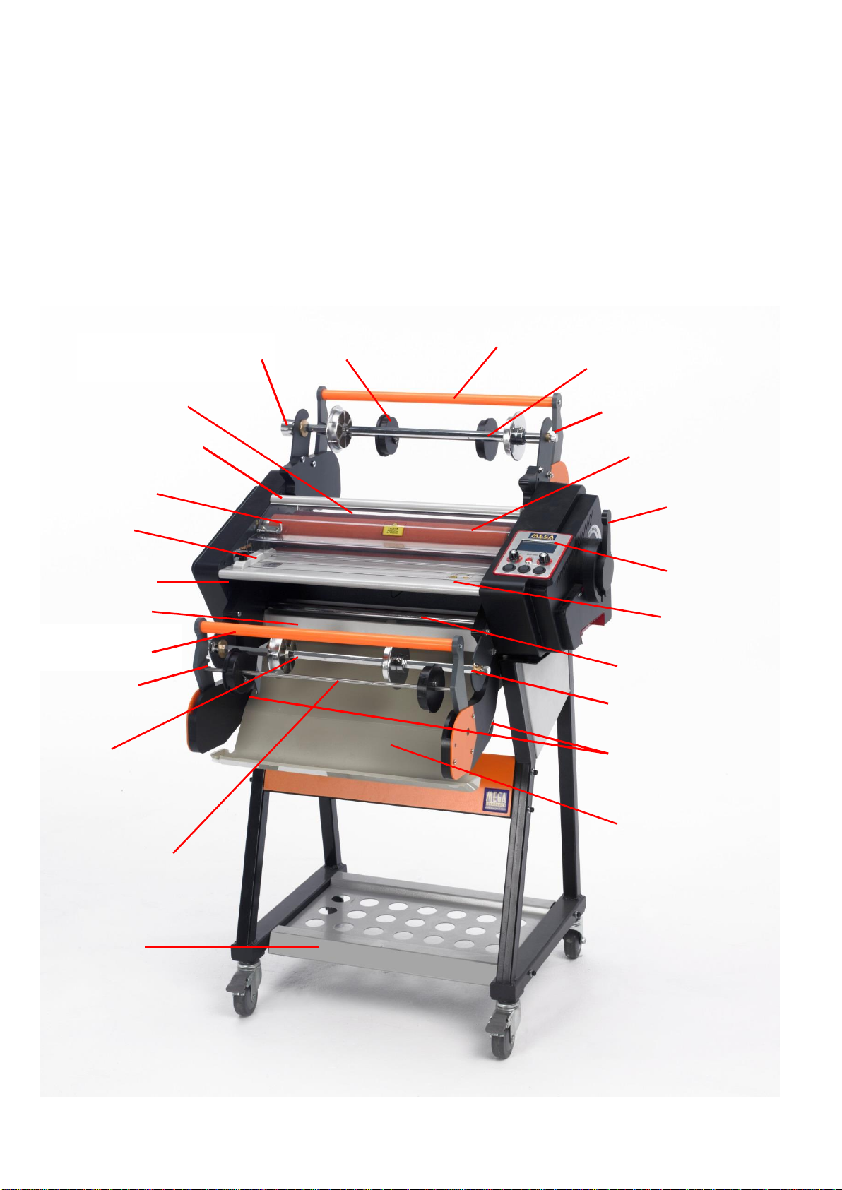
Machine parts.
Pull bar for top
take up roller
Top film mounting bar with
film roll support plates
Heated silicon rollers
Roller height
adjustment and
pressure leaver
Control panel
Feed tray
Bottom stabiliser bar
Bottom drip tray
Top film take up
roller shaft with
cardboard tube core
support plates
Top stabiliser bar
Safety cover and
Bottom bolt
Feed guide
Top drip tray
Pull bar for bottom
take up roller
Bottom film mounting
bar with film roll
support plates
Bottom film take up
roller shaft with
cardboard tube core
support plates
Stand base tray
Feed tray bolt
Safety cover top bolt
Bottom drip tray
Fixing slots
Slots for take up
roller shaft to sit
in
Mounting bar fixing knob
And pressure adjustment
Top mounting bar
fixing slot
Bottom mounting bar
fixing slot
4
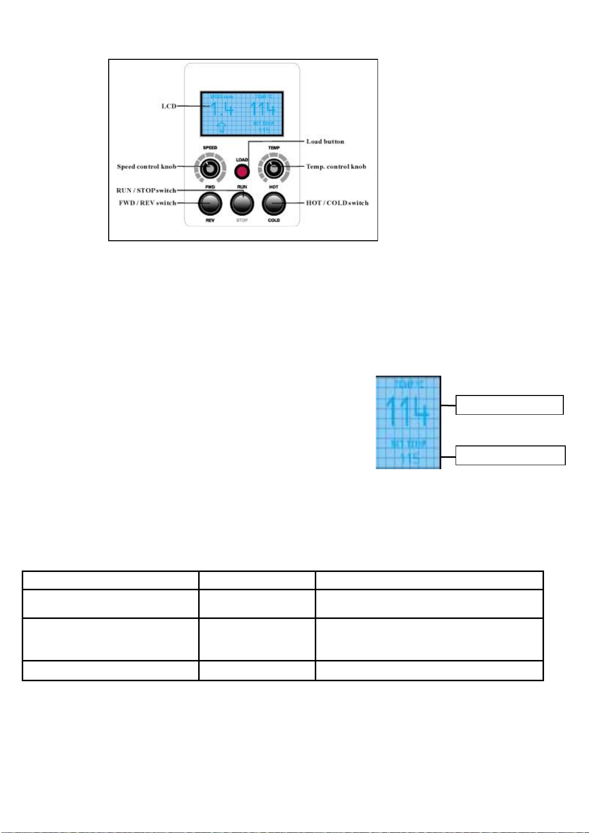
Control panel and functions of the digital display
Temperature control
The temperature setting you require for laminating can vary and can be affected by many different
factors, these include thickness of media, thickness and construction of laminating film, speed of the
machine and temperature and humidity of the room you are working in. Please refer to the guide at
the bottom of this page if you need help.
The temperature control dial will increase or decrease the set
temperature as it is turned and the set temperature will show on
the LCD display. The current temperature of the rollers will also
be displayed on the LCD display.
The temperature ranges from 0°C-140°C. If the temperature
reaches 140°C, the overheating protection function will
automatically activate to prevent the machine getting any hotter.
Approximate temperature guide
This chart is a rough guide only and should NOT be taken as an exact indication of the settings for
your laminating job. As previously stated, many different factors can affect the temperature and
speed required. The supplier does not accept responsibility for incorrect settings being applied.
Example film
Approx temperature
Approx speed
Ordyl 940 for non ferrous
materials
105°C - 110°C
0.6 - 1.0m per min
Ordyl 240E for ferrous
materials
120°C - 130°C
0.3 –0.6m per min (decrease speed for
thicker materials and increase
temperature slightly)
Dry film soldermask
105°C - 110°C
0.6 - 1.0m per min
Speed control
The speed control function allows adjustment of the speed of the machine. This can be manually
adjusted by turning the knob clockwise to increase the speed and anti-clockwise to decrease the
speed. The speed can range from 0M per min to 1.4M per min
Current Temperature
Set Temperature

5
Hot and cold settings
To change the function of the machine to either hot or cold press the HOT/COLD switch. When it is
switched to hot the set temperature will show on the LCD display. When it is switched to cold, COLD
will show on the LCD display.
Forward and reverse switch
The FWD/REV switch changes the working direction of the motor. When it is switched to forward the
motor will run forward and will show on the LCD display.
When it is switched to reverse the motor will run backwards and REVERSE will show on the LCD
display. This function is used to remove items fed in incorrectly or by mistake - please note removed
items will not be reusable.
Run and stop switch
The RUN/STOP switch enables you to start and stop the motor. When it is switched to RUN the
machine rollers will turn in the direction of the motor drive. If either the feed tray or guard are not in
place, the machine will not drive, however, by pressing the load button the rollers will operate while
the button is pressed to enable the film to be fed into the machine.
Operating instructions
Check the power voltage for the machine to ensure this meets your own supply. Plug the power cord
into the back of the machine and into your power supply. Contact your supplier if you do not have a
power cord with the machine.
Motor overload circuit breaker
If the machine should jam in a way that the motor could be affected, the circuit breaker will cut off the
power to avoid damage. Once the overload has been cleared, press the circuit breaker button and
the motor will start again. The circuit breaker button is located at the rear of the machine next to the
power switch. The button is red in colour.
Screen messages
Should the LCD display panel show the words OPN fault or CLS
fault, there may be a problem with your machine. In this instance,
turn off the power and call an engineer.
Familiarise yourself with the control panel before commencing
operation of the machine.
Turn on the power switch, the control panel
Display will light, this indicates the power is
connected

6
Work room lighting
Site the laminator in a well ventilated dust free area with suitable room lighting covered with yellow
film which blocks out light wavelengths under 450 nm. This is available from us part number 06-
14061. The film can also be used to cover any windows. N.B. Never leave the dry film photo resist
rolls in daylight or white light for any length of time. Always ensure the laminator is covered with a
suitable black light blocking material when not in use.
The Laminator
The laminator uses two rolls of Photo-resist and only two rolls of the same width can be used up to
450 mm in width for the 18” laminator and 650 mm for the 24” laminator. The dry film photo emulsion
is sandwiched between a polyester cover sheet and a peelable polyolefin sheet. The laminator
removes the polyolefin cover sheet before the film contacts the heated rollers; these rollers then fuse
with heat and pressure the photo emulsion on to both sides of the material. On exit the rear cold
pressure rollers continue to roll and fix the photo emulsion onto the material.
Film loading and threading
When you come to loading the film please use instructions below in conjunction with film
threading diagram on page 9.
1. Release the spring loaded bolt on the left front
underside of the feed tray and then lift the tray off
2. Release bottom bolt on safety guard. Lift guard up,
release top bolt and remove the safety guard.
7
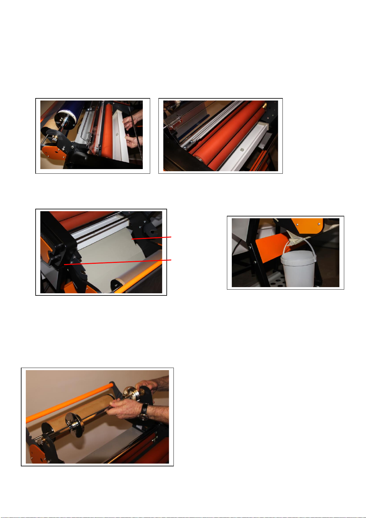
3. Optional
Please note that it is possible to wet laminate materials in our laminators perfectly safely.
For this reason we have provided a top and bottom drip tray which can be fitted as optional.
If the trays have not been fitted by us before shipping the laminator they can be fitted as
Follows:
(a) Top drip tray
This is fitted by tilting the tray at an angle and sliding it into position.
(b) Bottom drip tray
This is fitted into place by sliding it into the two bottom drip tray fixing slots
A bucket can be hung at the drain point of the bottom drip tray to catch any drops of water.
4. Pull back the top and bottom pull bars and remove the top and bottom film
mounting bars by undoing the fixing knobs and pulling the bars out of their fixing slots.
Right side
fixing slot
Left side fixing
slot
8
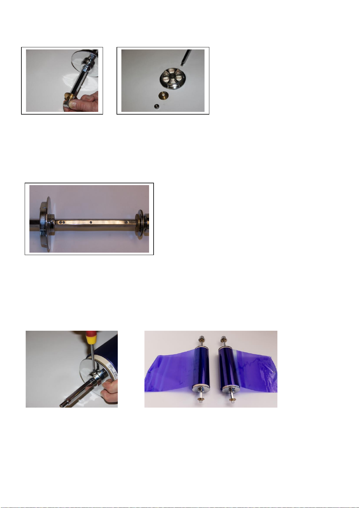
5. Undo the knurled screws at the end of the mounting bars and remove the brass plates
and the film roller support plates nearest to that end of the bars.
6. You will find two or three indents on the mounting bars at the end nearest the mounting bar
fixing knob. The film support plate screw must be screwed down into one of these indents.
It is recommend that rolls 305mm wide or smaller have the plate fixed in the indent position
furthest away from the knob end. With wider films you should use the indent nearest the knob.
Please ensure that the support plate is fitted in the same indent on both mounting bars. This
Will enable the top and bottom films to be lined up accurately when films are loaded.
7. For both rollers push the dry film roll core up against the support plate with the loose end of the film
hanging at the back of the roll and then replace the support plate you have removed and push it
into the other core end as far as it will go and tighten the support plate screw up onto the bar
making sure the screw is aligned with the screw of the first support plate.
8. Replace the brass plates and knurled screws and with the loose end of the dry film hanging at the
back of the roll for the top and bottom roller, fix the mounting bars back into the top and bottom
mounting bar fixing slots on the laminator with the pressure adjustment knobs on the right hand
side of the laminator when looking from the front. Make sure that the brass plates are on the
inside of the mounting bar holders and that the screw on the knurled knob end plate and the pin at
the fixing bar knob end are pointing out of the slot so that the plates push completely to the back of
the slots.
9
9. Untighten the allen screws which hold the cardboard core holders onto the take up roller bar and
position them on the bar so that the cardboard tube is in line with the dry film roll. Tighten the allen
screws to fix the core holders into position. Check that the take up roller bar is in the correct slot on
the push bar bracket. Short slot for 30 metre rolls of dry film. Long slot for 150 metre rolls of dry
film.
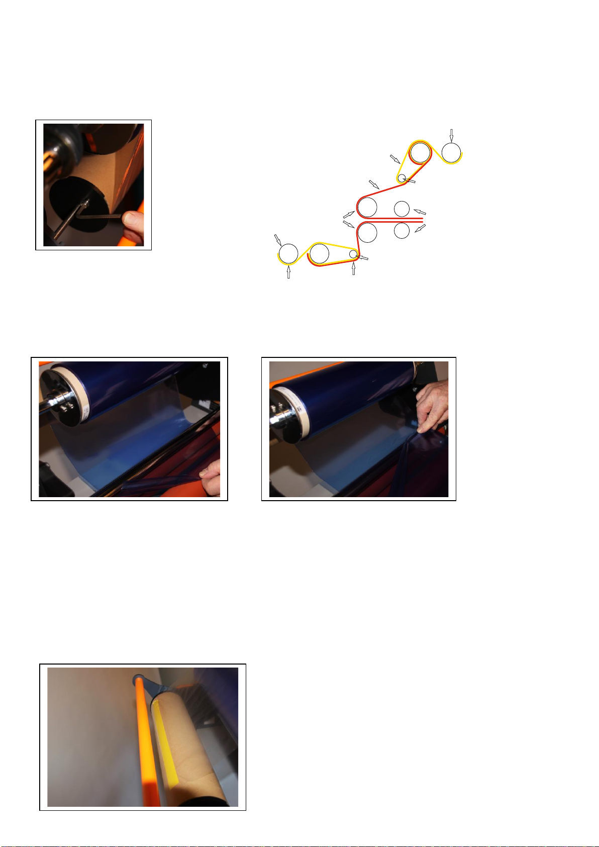
10. Pull the dry film from the top roller so that it goes underneath the top stabiliser bar and hangs
over the silicon rollers about 300-400mm
11. Cut two short pieces of sticky tape and stick one piece each side of the film diagonally
across a corner. Pull the pieces of tape away from each other and the polyolefin protective film
will pull away from the surface of the dry film resist coating.
Pull the polyolefin sheet away and pass it over the top of the dry film roll and under the take up
roll. Push the take up roll push bar forwards so the take up cardboard roll is against the dry
film roll. Adjust the position of the polyolefin film until it is exactly in line with the dry film and
then tape the polyolefin sheet along the length of the cardboard take up roll. Pull another 150
to 200mm of the dry film out to enable the take up roll to rotate one revolution to ensure that
the film is firmly in place on the roll.
Film threading diagram
BOTTOM TAKE UP
ROLLER
TOP TAKE UP
ROLLER
POLYOLEFIN
FILM
POLYOLEFIN
FILM
BOTTOM DRYFILM
PHOTORESIST
BOTTOM STABILISER
BAR
TOP STABILISER
BAR
TOP DRYFILM
PHOTORESIST
HEATED SILICONE
ROLLERS COLD EXIT
ROLLERS
10
12. Push the bottom stabiliser bar forwards and it will drop down and move towards you (see
machine parts drawing to enable you to locate the bar). Pass the bottom roll of dry film under the
stabiliser bar and back over the top of the roll of dry film then continue as in 10 above to separate
the polyolefin film from the dry film resist layer and to fix it to the bottom take up roller.
NB. Do not push the stabiliser bar back into its original position.
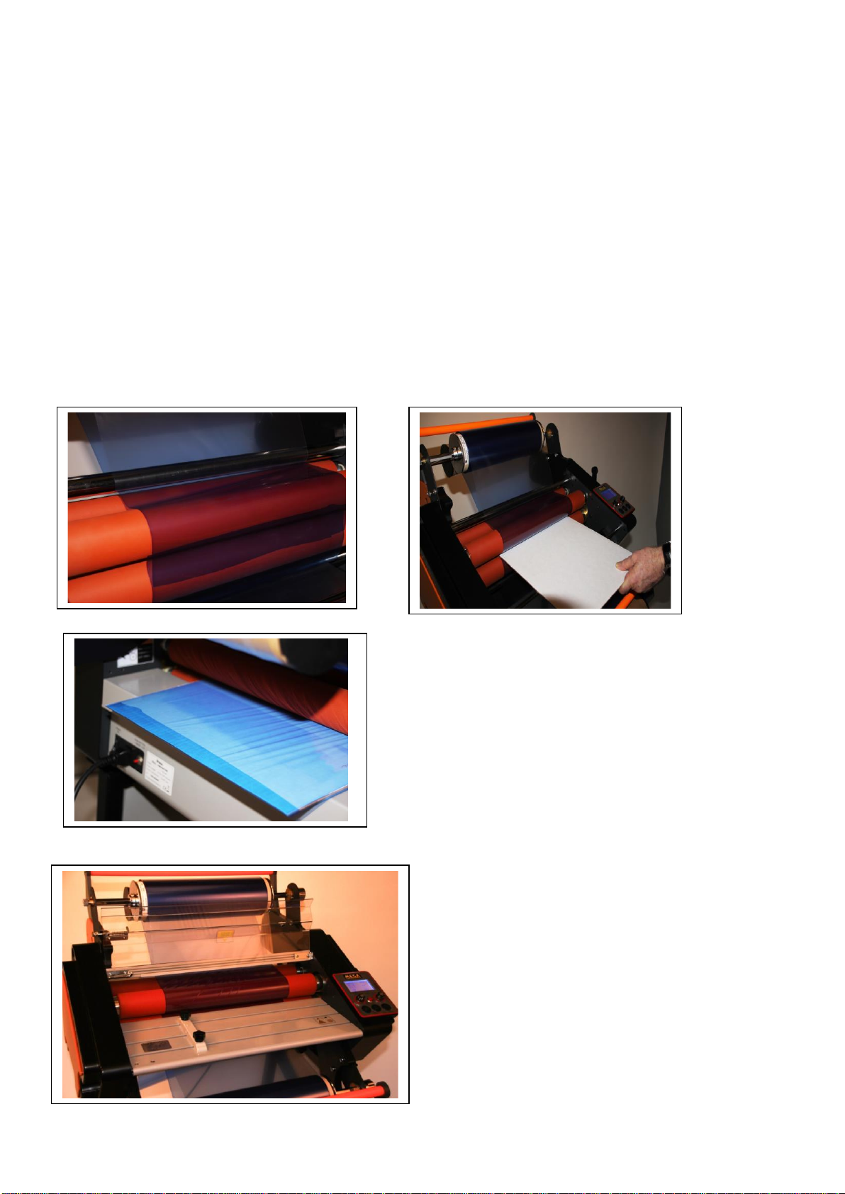
13. Cut the excess lengths of the top and bottom dry film so that they just overlap the entry
point of the heated silicon rollers using the film cutter provided, a
sharp blade or scissors.
Using the roller height adjustment and pressure leaver at the right hand side of the
laminator open the rollers to the maximum gap and using a piece of card slightly wider
than the film and about 200mm in length push the card and two pieces of overlapping film
between the rollers. Then push the height adjustment leaver down until it is exerting
pressure on the card.
Turn on the power and set the Hot/Cold switch to cold and the Stop/Run button to run. Set the
speed to 1.4 metres per minute and press and hold down the load button until the card and dry
film have pass through the laminator. NB if you need to continue running just the film through the
machine you may need to move the leaver further down.
14. Replace the safety guard and feed tray and your laminator is ready to use.
Finished loaded laminator.
This manual suits for next models
1
Table of contents
Other Mega Electronics Laminator manuals


