Mega MMP4 User manual

Maintenance Manual
SPECIALTY HAULAGE SOLUTIONS FOR CONSTRUCTION AND MINING
MEGA CORP.®
700 Osuna Rd. N.E. • Albuquerque, NM 87113 • 1-800-345-8889 • 505-345-2661 • Fax 505-345-6190
www.megacorpinc.com
® MEGA Corp., Inc. All Rights Reserved
MMP4-CAT(T4)-MX-2

MMP4-CAT(T4)-MX-2
26 Feb 2014
TABLE OF CONTENTS
A
Section 1 Definitions and Abbreviations . . . . . . . . . . . . . . . . . . . . . . . . . . . . . . . . . . . . . . . . . . . . . . . . .1-1
Section 2 System Description. . . . . . . . . . . . . . . . . . . . . . . . . . . . . . . . . . . . . . . . . . . . . . . . . . . . . . . . . . . .2-1
Section 3 Engine Control System . . . . . . . . . . . . . . . . . . . . . . . . . . . . . . . . . . . . . . . . . . . . . . . . . . . . . . . .3-1
Section 4 Basic Hydraulics System . . . . . . . . . . . . . . . . . . . . . . . . . . . . . . . . . . . . . . . . . . . . . . . . . . . . . . .4-1
Section 5 Water Pump Assembly . . . . . . . . . . . . . . . . . . . . . . . . . . . . . . . . . . . . . . . . . . . . . . . . . . . . . . . .5-1
Section 6 Axle and Suspension . . . . . . . . . . . . . . . . . . . . . . . . . . . . . . . . . . . . . . . . . . . . . . . . . . . . . . . . . .6-1
Section 7 Frame and Booms . . . . . . . . . . . . . . . . . . . . . . . . . . . . . . . . . . . . . . . . . . . . . . . . . . . . . . . . . . . . .7-1
Section 8 Scheduled Inspections . . . . . . . . . . . . . . . . . . . . . . . . . . . . . . . . . . . . . . . . . . . . . . . . . . . . . . . .8-1
Section 9 Special Inspections . . . . . . . . . . . . . . . . . . . . . . . . . . . . . . . . . . . . . . . . . . . . . . . . . . . . . . . . . . . .9-1
Section 10 Recommended Support Parts . . . . . . . . . . . . . . . . . . . . . . . . . . . . . . . . . . . . . . . . . . . . . . . .10-1
Section 11 Appendix A: MMP4 Build Drawings . . . . . . . . . . . . . . . . . . . . . . . . . . . . . . . . . . . . . . . . . . .11-A
Section 12 Appendix B: Hydraulic Pump and Engine Control. . . . . . . . . . . . . . . . . . . . . . . . . . . . . .12-A
Page

MMP4-CAT(T4)-MX-2
26 Feb 2014
TABLE OF CONTENTS
B (Blank)

1-1
MMP4-CAT(T4)-MX-2
26 Feb 2014
SECTION 1
Definitions and Abbreviations
Contents
MANUAL USAGE
This technical manual only contains information
required to safely maintain the MMP4 powered by a
CAT 2.2l TIER 4 diesel engine. See the CAT Engine
Maintenance and Operators Safety Manual
(SEBU8312-02) for specific vehicle system
information and maintenance procedures. If your
system is not covered in this manual please contact
MEGA Corp. Product Support at:
1-800-345-8889 or visit our web site at
www.megacorpinc.com for more detailed
information.
Descriptions of the hazards are reviewed in this
section. All personnel working on or operating the
machine must become familiarized with all the safety
messages.
Due to the nature of these processes, ensure that all
safety information, warnings and instructions are
read and understood before any operation or any
maintenance procedures are performed. Some
procedures take place with heavy components and
at moderate heights, ensure proper safety
procedures are maintained when performing these
actions. Failure to use and maintain proper safety
equipment and procedures will cause injury, death or
damage to equipment.
WARNING, CAUTION AND NOTES
The following definitions are found throughout the
manual and apply as follows:
Operating procedures and techniques, which could
result in personal injury and/or loss of life if not
carefully followed.
Operating procedures and techniques, which could
result in damage to equipment if not carefully
followed.
Operating procedures and techniques that are
considered essential to emphasize.
USE OF SHALL, WILL, SHOULD AND MAY
Shall and Will – Used when application of a
procedure is mandatory.
Should – Used when application of a procedure is
recommended.
May - Used to indicate an acceptable or suggested
means of accomplishment.
Manual Usage ...................................................................1-1
Warning, Caution And Notes ......................................1-1
Use Of Shall, Will, Should And May ...........................1-1
Safety Messages ..............................................................1-2
Abbreviations ...................................................................1-3
MMP4 General Overview (Typical) ...........................1-4

MMP4-CAT(T4)-MX-2
26 Feb 2014
SECTION 1
Definitions and Abbreviations
1-2
SAFETY MESSAGES
There are several specific safety messages in this
section that are applicable to the MMP4. These
hazards are reviewed in this section. All personnel
working on or operating the machine must become
familiarized with all the safety messages.
(Applicable to safety labels on machine) Make sure
that all of the safety messages are legible. Clean the
safety messages or replace the safety messages if you
cannot read the words. Replace the illustrations if the
illustrations are not legible. When you clean the
safety messages, use a cloth, water and soap. Do not
use solvent, gasoline or other harsh chemicals to
clean the safety messages. Solvents, gasoline or
harsh chemicals could loosen the adhesive that
secures the safety messages. Loose adhesive will
allow the safety messages to detach.
Replace any safety message that is damaged or
missing. If a safety message is attached to a part that
is replaced, install a new safety message on the
replacement part.
DO NOT OPERATE (2)
Do not open this control box unless you read and
understand the instructions and warnings in the
Operator and Maintenance Manual. Failure to
follow instructions or heed the warnings could
result in serious injury or death.
BACKING RUNOVER HAZARD (3)
The vehicle is equipped with a back-up alarm.
Alarm must sound when operating this vehicle in
reverse. Failure to maintain a clear view in the
direction of travel could result in serious injury or
death.
NON-POTABLE (5)
Water held within the MMP4 is not potable. Do
not use the MMP4 for transport of water intended
for human or animal consumption, as serious
injury or death may result.

MMP4-CAT(T4)-MX-2
26 Feb 2014
SECTION 1
Definitions and Abbreviations
1-3
FALL HAZARD (7)
Do not walk on the top of tank without fall arrest
PPE. Serious injury or death could occur from a
fall.
ROTATING SHAFT (8)
Do not place your hand or tools within pump bell
while pump is rotating and/or pressure held
within the motor supply hose. Refer to the
Operator and Maintenance Manual for the
procedures to operate and maintain the pump.
Failure to follow proper procedures could result in
serious injury.
HIGH PRESSURE MOTOR (11)
Hydraulic motor and supply lines contain oil
under high pressure. Improper removal and
repair procedures could cause severe injury. To
remove or repair, instructions in the Maintenance
Manual must be followed.
ABBREVIATIONS
cc - Cubic Centimeters
CCW - Counter Clockwise
CW - Clockwise
fl. oz. - Fluid Ounce
FT - Feet
FPM - Feet Per Minute
GPM - Gallons Per Minute
IN/SQ FT - Inches per Square Feet
KM-H - Kilometers Per Hour
Kg - kilograms
kPa - Kilopascals
l - liters
lpm - Liters per minute
LT - Left as viewed from the operator’s position facing
forward
m - meters
MPH - Miles Per Hour
MMP - MEGA Mobile Pump
Nm - Newton meters of torque
psi - pounds per square inch
RPM - Revolutions Per Minute
RT - Right as viewed from the operator’s position
facing forward
SQ FT - Square Feet
VDC - Volts, Direct Current

MMP4-CAT(T4)-MX-2
26 Feb 2014
SECTION 1
Definitions and Abbreviations
1-4
MMP4 GENERAL OVERVIEW (TYPICAL)
18
12
7
9
5
3
1DISCHARGE BOOM
2VACUUM BREAK
3TOW HITCH
4CAT C2.2T DIESEL ENGINE
5LANDING GEAR (QTY 3)
6TIRE AND RIM ASSEMBLY
7FENDER
850 GAL. DIESEL FUEL TANK
9DISCHARGE BOOM LIFT CYLINDER
TOP VIEW
SIDE VIEW
2
4
10
11
10 TAIL LIGHTS
11 HYDRAULIC OIL TANK
12 INLET DEBRIS SCREEN AND SAFETY CHAIN
13 AXIAL WATER PUMP
14 INLET BOOM
15 HYDRAULIC CONTROL VALVE
16 INLET BOOM CYLINDER
17 ENGINE CONTROL BOX
18 BATTERY BOX
14 15 17 13
13 12
3
5
614
10
11
18
16

2-1
MMP4-CAT(T4)-MX-2
26 Feb 2014
SECTION 2
System Description
Contents
DESCRIPTION
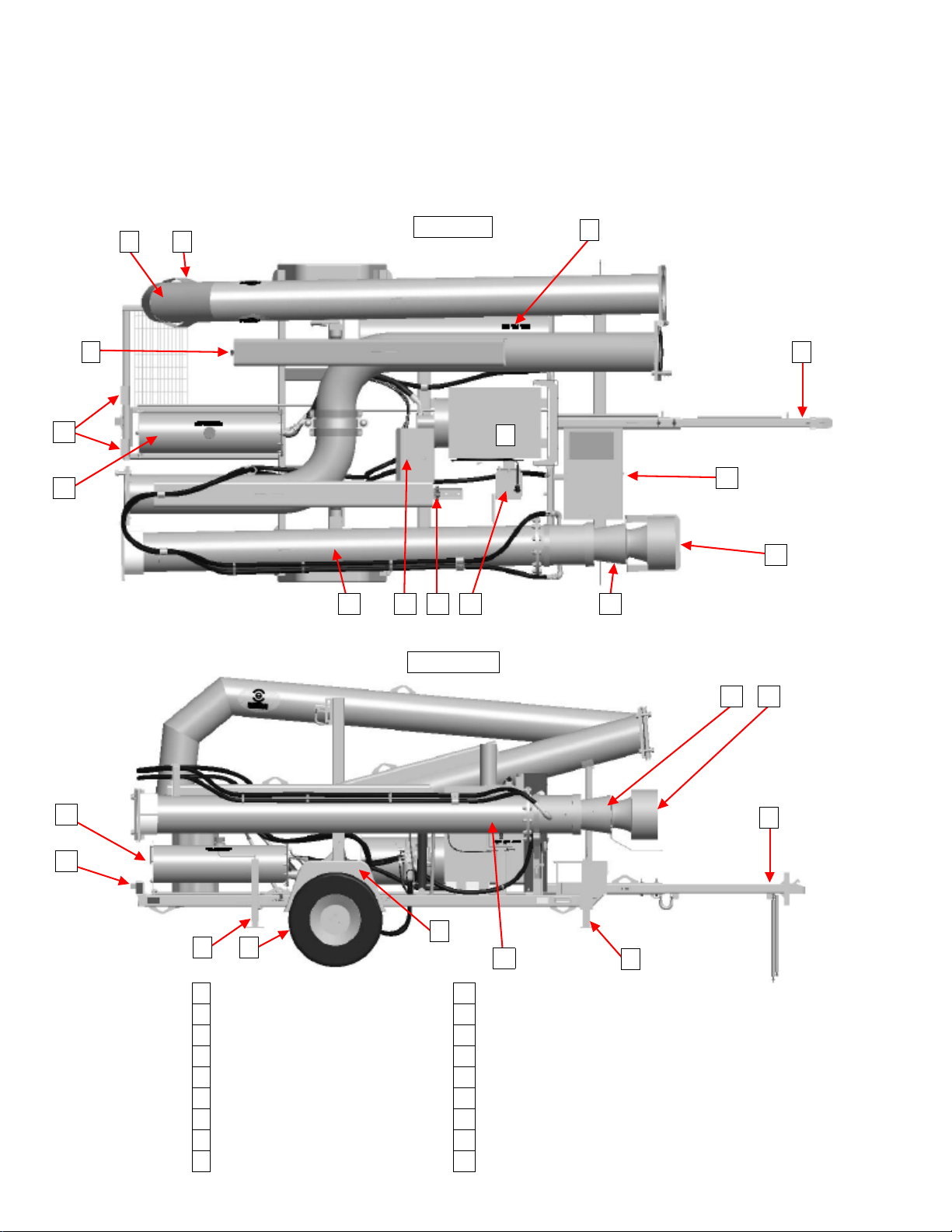
The MEGA Mobile Pump (MMP4) is a towable water
lifting station. The MMP4 may be towed by a vehicle
capable of at least a 6,000 pound (2,725 kg) towing
capacity, 1,000 pound (450 kg) tongue weight, and
equipped with the appropriate weight rated Class IV
trailer hitch with a 2 5/16 inch ball. The MMP4 can be
transported to a water holding pond and be set up
by one individual.
The MMP4 is a self-contained pumping station fitted
with a hydraulically driven 12 inch axial water pump
that has the potential to lift water 25 feet (7.6 meters)
from pump level to fill water distribution equipment
(maximum height: 17 feet or 5.2 meters above
ground level).
MMP4s are equipped with: hydraulically lifted inlet
and discharge booms with safety retaining chains
and travel locking devices, DOT rated lighting, 16
inch load range 'E' on-highway trailer tires, a fold
away hitch with safety chains, a vacuum break with
an anti-siphon discharge sock on the discharge
boom, 23 gallon (87 liter) hydraulic oil tank filled with
Chevron Clarity AW 46 hydraulic oil, a gear type
hydraulic pump driven by a Caterpillar C2.2T series
diesel engine, and a 50 gallon (190 liter) capacity
diesel fuel tank equipped with shut off valves.
The MMP4 needs a minimum of 2.5 feet (0.76 meters)
of water above the inlet of the water pump for proper
operation.
INSPECTION
1. Inspect MMP4 exterior paint for wear and
corrosion.
2. Inspect piping for damage and leaks.
3. Inspect frame, landing gear and suspension for
damage and missing parts.
4. Inspect engine assembly for loose, missing,
damaged or leaking parts.
5. Inspect all hydraulic hoses and couplings for
security, damage and leaking.
6. Inspect fuel, engine oil, anti freeze and hydraulic
oil for contamination and proper level.
7. Inspect lighting, lug nuts, fenders and hitch
safety equipment for operation, damage and
missing parts.
8. Inspect electrical system for corrosion, damage
and missing parts.
Description ........................................................................2-1
Inspection ...........................................................................2-1
Repair ...................................................................................2-2

MMP4-CAT(T4)-MX-2
26 Feb 2014
SECTION 2
System Description
2-2
REPAIR
Paint
Remove corrosion, prime and paint.
Engine Fluid Levels and Inspections
Adjust, repair or service according to CAT C2.2T
manuals (SEBU8312-02) for engine service schedule.
Leaks
1. Remove paint and corrosion from suspected area.
2. Prep surface to be welded, weld over leak.
3. Prime and paint over weld.
4. Tighten or replace damaged or leaking
component.
Lighting
Repair as required to maintain DOT compliance.
Missing parts
Contact MEGA Corp Parts sales for assistance.
Structure
Contact the MEGA Corp. Product Support Group at:
Toll free US 1-800-345-8889
Direct 1-505-345-2661
or visit our website at www.megacorpinc.com for
more detailed contact information or assistance on
major structural repairs.

3-1
MMP4-CAT(T4)-MX-2
26 Feb 2014
SECTION 3
Engine Control System
Contents
DESCRIPTION
The Engine Control System consists of: A control box
with lockable cover, ignition switch with key, throttle
control, battery voltage gauge, engine oil pressure
gauge, engine coolant temperature gauge, hour
meter, fault indicator lamps, and an engine
tachometer.
The engine control box controls and monitors the
main engine functions. It is equipped with:
• Oil pressure gauge to monitor the engine oil
pressure.
• Engine coolant temperature to monitor the
engine coolant temperature.
• Tachometer to monitor the engine RPM’s or
speed.
• Battery voltage meter to monitor the battery
voltage.
• Battery voltage meter to indicate the state of
charge and electrical operation of system.
• Engine hour meter to indicate engine operational
hours.
• Fault Indicator Lamps to indicate potential unsafe
operating conditions and to show fault in
individual systems.
• Hand throttle to adjust the engine operating
RPM’s.
• Remote Engine Stop Button
INSPECTION
1. Inspect control box and cabling for security,
condition and mounting.
2. Inspect switches, gauges and throttle control for
security, damage and operational condition.
REPAIR
SWITCH REPLACEMENT
1. Remove power to the engine control.
2. Remove engine control face plate to gain access
to the switch.
3. Mark wiring on old switch before removal to
ensure correct wiring configuration is
maintained.
4. Remove old switch and replace with the same
type of switch.
5. Install wiring on new switch as previously
marked.
6. Install engine control face plate in control box.
7. Apply power to the engine control and perform
functional check of the newly installed switch.
Battery
Volt-meter
Engine Oil
Pressure
Gauge
Fault
Indicator
Lamps
Engine Start/Stop
Key Switch
Engine Hour
Meter
Engine
Coolant
Temperature
Gauge
Tachometer
Hand Throttle
Description.........................................................................3-1
Inspection ...........................................................................3-1
Repair ...................................................................................3-1

MMP4-CAT(T4)-MX-2
26 Feb 2014
SECTION 3
Engine Control System
3-2
INDICATOR GAUGE REPLACEMENT
1. Remove power to the engine control.
2. Remove engine control face plate to gain access
to gauge and wiring.
3. Mark wiring on old gauge before removal to
ensure correct wiring configuration is
maintained.
4. Remove old gauge and replace with the same
type of gauge.
5. Install wiring on new gauge as previously
marked.
6. Install engine control face panel in control box
7. Apply power to the engine control and perform
functional check of newly installed indicator
gauge.
ENGINE TACHOMETER REPLACEMENT
1. Remove power to the engine control.
2. Remove engine control face plate to gain access
to the backside of the tachometer.
3. Mark wiring on old tachometer before removal to
ensure correct wiring configuration is
maintained.
4. Remove old tachometer and replace with the
same type tachometer.
5. Installed wiring on new tachometer as previously
marked.
6. Install engine control plate in control box.
7. Apply power to engine control and perform
functional check of newly installed tachometer.
THROTTLE CONTROL REPLACEMENT
1. Remove power to the engine and engine control
system.
2. Loosen cable locking screw on throttle lever on
fuel injection pump.
3. Remove cable jam nut on lever side of the fuel
pump mounting bracket.
4. Remove cable jam nut on throttle adjusting end
of cable.
5. Remove cable assembly.
6. Install new throttle cable assembly in mounting
bracket.
7. Thread jam nut on throttle cable adjusting end
behind mounting bracket.
8. Route throttle cable to the fuel pump cable
mounting bracket.
9. Run cable through fuel pump mounting bracket.
10. Install jam nut on fuel pump throttle lever side of
bracket.
11. Insert throttle cable in the pivot on the throttle
lever of the fuel pump.
12. Ensure throttle cable and fuel pump throttle lever
is in the idle position.
13. Secure the throttle cable locking screw on the
new cable.
14. Ensure the new throttle cable is routed away from
moving parts.
15. Ensure throttle cable is secure.
16. Check operation of newly installed cable for
smooth operation.

MMP4-CAT(T4)-MX-2
26 Feb 2014
SECTION 3
Engine Control System
3-3
17. Ensure newly installed throttle cable allows
engine throttle lever to fully contact the LOW idle
stop.
18. Ensure the newly installed throttle cable allows
engine throttle to fully contact the HIGH idle stop.
19. Place throttle control cable in the low idle
position.
20. Apply power to engine control box and engine.
21. Ensure hydraulic ball valve at hydraulic tank is
OPEN.
22. Perform functional check to ensure proper
engine low and high idle RPMs. If engine RPMs
are out of specified range, check throttle cable
adjustment again and refer to CAT C2.2T engine
manual (SEBU8312-02) for correct RPM
specifications and adjustment procedures.

MMP4-CAT(T4)-MX-2
26 Feb 2014
SECTION 3
Engine Control System
3-4 (Blank)

4-1
MMP4-CAT(T4)-MX-2
26 Feb 2014
SECTION 4
Basic Hydraulics System
Contents
DESCRIPTION
The MMP4 hydraulic system originates at a hydraulic
pump coupled to a CAT C2.2T Diesel engine. The
system draws hydraulic oil from a hydraulic tank
mounted at the rear of the MMP4 frame through an
inlet screen inside of the tank and a shut off valve on
the outside of the tank. The hydraulic pump moves
the oil to a hydraulic control valve mounted to the
right side of the unit. The control valve diverts and
regulates the oil flow and pressure through the
MMP4 system. The Hydraulic control valve is used to
control the raising and lowering of the 2 hydraulic
cylinders attached to the inlet and discharge booms.
The hydraulic control valve also controls the
hydraulic drive motor inside of the water pump at the
end of the inlet boom; this control feature is
equipped with a detent to allow the lever to stay in
the ON position during water pump operation, and is
equipped with a pressure relief valve to protect
against over-pressurization of the hydraulic system.
The return hydraulic oil is passed through a hydraulic
oil filter, oil cooler, and then a diffuser mounted
inside of the hydraulic oil tank.
HYDRAULIC TANK ASSEMBLY
DESCRIPTION
The hydraulic tank consists of an inlet screen, return
oil diffuser, internal baffle, shut off valve, oil level
sight gauge, reservoir cap and breather. The system
draws oil from the bottom of the tank through an
inlet screen to pre-filter the oil. The shut off valve (if
equipped) holds the oil inside of the tank when
servicing the hydraulic system. The sight gauge is
used as a visual indicator of the hydraulic oil quality
and quantity. The Internal baffle allows for oil
movement with in the tank to evenly distribute the
return oil trough out the reservoir. The return diffuser
inside of the hydraulic tank just below the normal oil
level reduces the potential for hydraulic oil foaming
in the tank. The reservoir cap and breather allow
filling of the hydraulic tank and prevent dirt and
debris from entering the hydraulic system.
INSPECTION
1. Inspect hydraulic oil tank for security, damage,
and leaks.
Description.........................................................................4-1
Hydraulic Tank Assembly ..............................................4-1
Hydraulic Pump................................................................4-2

MMP4-CAT(T4)-MX-2
26 Feb 2014
SECTION 4
Basic Hydraulics System
4-2
2. Check hydraulic oil level and quality. The level
should be between 80% and 90% of the level
visible in the sight glass and clear.
3. Check hydraulic tank filler cap, breather and bolt
on end cover for security, damage and leaks.
4. Check hydraulic hose fittings and shut off valve,
ensure shut off valve is open.
5. Check tank mounting bolts, ensure the bolts are
tight.
REPAIR
Repair, secure or adjust as required.
HYDRAULIC PUMP
DESCRIPTION
The hydraulic pump is coupled to the flywheel end of
the engine. The hydraulic pump moves the oil
through the system to generate flow and pressure
needed to operate the water pump and boom
cylinders. The pump draws oil from the hydraulic
tank and moves it to the hydraulic control valve
where the control valve directs the oil flow to the
selected components.
INSPECTION
Inspect hydraulic pump, adapter and hosing for
vibrations, unusual noises, security, damage and
leaks.
REPAIR
Repair or replace as required.
WATER PUMP HYDRAULIC DRIVE MOTOR
The hydraulic drive motor is coupled to the water
pump drive shaft inside the water pump. The drive
motor is controlled by the hydraulic control valve,
water pump spool. When the lever is moved to the
ON position the fluid is directed to the drive motor
causing the water pump impeller to rotate, moving
water up the inlet boom.
INSPECTION
1. Check water pump drive motor fittings for
security, damage and leaks.
2. Check for an oily film on water surface
(indications of hydraulic oil leak below the
surface of the water). If water pump is
submerged.
3. Check for oil residue inside of the inlet to the
water pump. If water pump is in the travel
position.
REPAIR
Repair or replace as required.
OPEN
CLOSED

MMP4-CAT(T4)-MX-2
26 Feb 2014
SECTION 4
Basic Hydraulics System
4-3
HYDRAULIC CONTROL VALVE
The hydraulic control valve controls all of the oil
flowing from the hydraulic oil pump and controls its
flow and pressures. The valve is attached to the rear
of the accessory drive housing of the engine. The
control valve consists of:
INSPECTION
1. Check hydraulic control valve mounting for
security, damage and leaks.
2. Check control valve levers for ease of operation,
security, damage and missing parts.
3. Check control valve fittings and metering valves
for security, damage and leaks.
4. Check pressure regulator for proper relief
pressure (2,800 psi/19,300 kpa), security and
leaks.
REPAIR
Hydraulic Control Valve
1. Repair, adjust or replace as required.
2. To set hydraulic relief pressure, install a 0 – 3,000
psi (0 – 21,000 kpa) pressure gauge on the test
fitting located on the side of the control valve as
shown below.
3. With the engine operating at high idle, operate
the inlet boom UP switch and observe the
reading on the pressure gauge.
1Discharge Boom Valve 7System Return Test Port
2PUMP Boom Valve 8Pump Motor Test Port
3Main System Pressure Relief 9Dump Valve
4Discharge Boom Speed Control 10 Water Pump Start Valve
5Pump Boom Speed Control 11 Hydraulic Oil Filter
6System Pressure Test Port
1
2
3
4 5
6
7
8
9
10
4
5
6
11

MMP4-CAT(T4)-MX-2
26 Feb 2014
SECTION 4
Basic Hydraulics System
4-4
4. If the hydraulic oil pressure is not within the
specifications, adjust the pressure regulator
cartridge as follows:
a. To increase the pressure, loosen the lock nut
on the regulator stem and screw in the stem
clockwise (CW) until the pressure is at 2,800
psi (19,300 kpa), tighten lock nut on stem.
b. To reduce the pressure, loosen the lock nut on
the regulator stem and unscrew the stem
counter clockwise (CCW) until the proper
pressure is obtained, tighten lock nut on
stem.
c. Recheck hydraulic pressure.
d. Shut unit off.
e. Remove pressure gauge from test port.
Hydraulic Cylinder Speed Control Valve
1. If the hydraulic boom cylinders raise too slowly or
lower too fast, check the adjustment as follows;
a. Remove protective cap.
b. Loosen jam nut.
c. Fully seat the flow control on the hydraulic
control valve for the cylinder with the travel
speed that needs adjustment.
d. Rotate knob 1/2 turn CCW.
e. Raise boom, check speed to ensure speed is
desired, if speed is too fast turn knob CW 1/
16th of a turn at a time, if the speed is too slow
turn knob CCW 1/16th of a turn at a time until
desired speed is achieved (8 seconds to full
rise).
f. Tighten jamb nut.
g. Reinstall cap.
HYDRAULIC CYLINDERS
The 2 hydraulic cylinders are used for lifting the inlet
and discharge booms to either the 'stow/travel'
position or to the 'fill' position. When the boom
control switch is operated in the 'UP' position, the
pressurized oil retracts the cylinder and lifts the
boom. The speed of the lifting and lowering is
controlled by metering valves built into the hydraulic
control valve. There are safety chains at each cylinder
to prevent any unwanted movement in the boom
when it is filled with water and as a safety precaution
in case the control valve lever is operated
accidentally. The cylinder operates in the boom
down mode by activating the control valve in the
'DOWN' position, the weight of the boom makes the
cylinder extend, lowering the boom, the built in
metering valve controls the lowering speed of the
boom.
Torque 24-26 ft-lbs flow
control for “discharge pipe”.
Set flow for 8 sec. rise.
Torque 24-26 ft-lbs flow
control for “pump pipe”.
Set flow for 8 sec. rise.
Retract.
‘Pump Pipe’
Test Port. ‘System Pipe’

MMP4-CAT(T4)-MX-2
26 Feb 2014
SECTION 4
Basic Hydraulics System
4-5
INSPECTION
1. Check hydraulic cylinders for security, damage
and leaks.
2. Check hydraulic cylinder safety chains for
security, missing parts and damage.
3. Check hydraulic hoses and metering valves for
security, damage and leaks.
4. Check for proper operation and alignment.
REPAIR
Repair, adjust or replace as required.
HYDRAULIC FILTER
The spin on hydraulic oil filter is in the return to tank
hydraulic circuit. All hydraulic oil passing through the
system passes through the filter prior to the hydraulic
oil cooler. The filter is rated at 400 psi (2,758 kpa). The
filter is rated at 10 microns and the filter housing has
a built in bypass valve to bypass the filter element
when the inlet pressure is too high or the filter
becomes restricted.
INSPECTION
1. Inspect hydraulic oil filter mounting for security
and damage.
2. Check hydraulic filter for leaks and damage.
3. Check hydraulic filter assembly hose fitting
adapters for security and leaks.
REPAIR
Repair, adjust or replace as required.
HYDRAULIC OIL COOLER
The hydraulic oil cooler is attached to the front of the
engine radiator. The engine cooling fan draws cool air
through the oil cooler lowering the oil temperature.
The oil cooler is in the return to tank hydraulic circuit.
Built into the oil cooler is a bypass valve that allows
oil to bypass the cooler if the return oil pressures are
too great (e.g; when the hydraulic oil is cold). The oil
cooler and engine coolant radiator are protected by a
steel mesh guard to prevent damage to the cooler
and radiator.
INSPECTION
1. Check hydraulic oil cooler and radiator guard for
security and damage.
2. Check hydraulic oil cooler and fittings for leaks.
3. Check hydraulic oil cooler for blockage and
debris that may interfere with proper cooling of
oil passing through cooler assembly.
REPAIR
1. If cooling fins are dirty or plugged with debris,
remove, replace or clean cooler as required.
2. Tighten or replace leaking or damage adapter
fittings as required.
3. Replace radiator guard if damage is present.

MMP4-CAT(T4)-MX-2
26 Feb 2014
SECTION 4
Basic Hydraulics System
4-6
HYDRAULIC HOSES
The MMP4 is equipped with hydraulic hosing to
convey the hydraulic oil pressure and flow to
components that are operated by the hydraulic
control valve. These hoses are sized according to the
volume and pressure requirements of the
component. The hydraulic drive motor for the water
pump utilizes a 1 inch (-16) hose to direct the volume
of oil required to turn motor that drives the impeller
of the water pump at the rated speed. The hydraulic
cylinder hoses require a smaller volume of fluid and
do not require as large of a hose. The makeup oil
requirement for the lift cylinders (when the booms
move down) are low pressure and low volume. The
suction side of the hydraulic pump requires suction
rated hydraulic hose, this prevents the hose from
collapsing under suction loads.
INSPECTION
Inspect for damage, security, and leaks.
REPAIR
1. Remove and replace damaged hose assembly if
damage to outer covering is present or leaks are
present.
2. Replace hose assembly if hose end is
unserviceable due to leaks or damage.

5-1
MMP4-CAT(T4)-MX-2
26 Feb 2014
SECTION 5
Water Pump Assembly
Contents
DESCRIPTION
The water pump assembly is comprised of; hydraulic
drive motor, water pump housing, impeller, shaft and
bearings and an inlet screen. The water pump
assembly uses hydraulic oil flow produced by the
engine driven hydraulic oil pump to turn the
hydraulic drive motor which is directly coupled to the
water pump impeller. Water pump speed is
controlled by the hydraulic control valve and
pressure relief cartridge which diverts the oil flow to
the inlet port (pressure) of the hydraulic drive motor
to the return oil hose for the hydraulic system. The
pressure relief cartridge diverts excessive oil pressure
directly to the hydraulic return hose, returning back
to the hydraulic oil to the tank for system protection.
HYDRAULIC DRIVE MOTOR
A gear-type hydraulic motor mounted inside the
water pump assembly. The hydraulic motor receives
hydraulic oil flow from the hydraulic system
controlled by the hydraulic control valve at 1,900 -
2,800 PSI (13,000 - 19,300 kpa) and flow rates up to 35
GPM (135 lpm) for operation. The hydraulic motor is
coupled directly to the water pump shaft and rotates
in a clockwise (CW) direction as viewed from the inlet
of the pump. The speed and volume of the water
pump is dependent on the engine RPMs, [e.g: higher
engine RPMs yields a higher output volume of water].
INSPECTION
1. Check for excessive vibration and noise.
2. Check water pump for security and leaks.
3. Check and adjust fluid levels.
4. Check hydraulic system for security and leaks.
SERVICE
1. Park unit on level ground, lower and secure
stabilizing jacks to make unit stable for
maintenance.
Ensure the MMP4 is properly positioned and
configured before maintenance is performed.
Units not configured properly or stabilized, may
rollover and cause serious personal injury or
death.
2. Remove all electrical and hydraulic power to
make the unit safe for maintenance.
Ensure the MMP4 is made safe for maintenance.
Performing maintenance on a unit with hydraulic
and electrical power applied may result in serious
personal injury or death.
Description.........................................................................5-1
Hydraulic Drive Motor ....................................................5-1
Inspection ...........................................................................5-1
Service .................................................................................5-1
Disassembly.......................................................................5-5
Assembly.............................................................................5-6
Table of contents
Other Mega Construction Equipment manuals
Popular Construction Equipment manuals by other brands

Ammann
Ammann ARX 36-2 KU St V 2022 operating manual

Amco Veba
Amco Veba 910NG user manual

AIRLESSCO
AIRLESSCO 24E365 600 Series Operation - repair - parts

Graco
Graco LineLazer ES 1000 Installation, Repair, Parts

Komatsu
Komatsu PC4000 Assembly procedure

Altrad Belle
Altrad Belle MINIMIX 150 Operator's manual

Tigercat
Tigercat AD610C Service manual

EGAmaster
EGAmaster CURVAMATIC-3 operating instructions

Haufftechnik
Haufftechnik MIS 90S Assembly instructions

Z.I.P.P.ER MASCHINEN
Z.I.P.P.ER MASCHINEN ZI-BR160Y user manual

Sherman + Reilly
Sherman + Reilly Revolution Series Operator's manual

Haufftechnik
Haufftechnik ESH Basic-FUBO-GK/MBK Assembly instructions